Downloaded 2,815 times


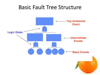


Fault Tree Analysis (FTA), developed in 1962, is a deductive method used to identify the causes of undesired events through logic diagrams and Boolean algebra. The analysis involves constructing a fault tree to illustrate event relationships and assigning probabilities to determine the likelihood of the top event occurring. FTA is advantageous for analyzing complex systems but can be challenging due to variations in tree structures and potential redundancies.