2. the two segments l0 of the protector-cable combination differ
substantially from each other. With the closeness of l0 to the
suspension clamp at equal T the relative strain åm decreases,
i.e., åm varies over the length of the protector. Therefore, we
should presume that within Äl0 the relative strain in each sec-
tion of the protector-cable combination decreases with close-
ness of the section to the suspension clamp. Consequently,
for the protector-cable combination the measured values of
åm on the length l0 of the protector should be referred to the
middle of l0. In what follows the relative strains measured for
the protector-cable combination will be denoted å1m (at a dis-
tance l = 400 mm from the middle of the suspension clamp)
and å2m (at a distance l = 900 mm from the middle of the sus-
pension clamp).
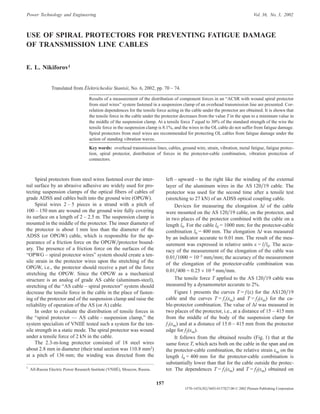
According to the data of Fig. 1 the dependence of the
tensile strength T acting on the tested cable AS 120/19 on
the relative strain å is approximated by an exponential func-
tion
T1 = a1 exp b1å, (1)
where a1 = 1.89221, b1 = 860.741, and the correlation coeffi-
cient r1 = 0.98644 (for the given cable).
Equation (1) is applicable to both the cable in the span
and to the part of the cable under the protector.
Measurements show that for the “protector-cable AS120/19”
combination the dependence of the mean value of the rela-
tive strain åm (Fig. 1) in the middle of l0 on the tensile force T
can be approximated by the expression
åm = a2T + b2. (2)
The values of parameters in Eq. (2) for the distances
l1 = 400 mm and l2 = 900 mm from the middle of the suspen-
sion clamp are presented below (r2 is the correlation coeffi-
cient).
l1 = 400 mm l2 = 900 mm
a2 9.042 ´ 10–5
1.152 ´ 10–4
b2 1.531 ´ 10–5
3.172 ´ 10–4
r2 0.99842 0.99705
We use Eq. (2) to calculate å1m in the middle of the seg-
ment l0 for a given force T acting on the protector-cable com-
bination and on the wire outside the protector-cable combi-
nation at a distance l = 400 mm from the middle of the sus-
pension clamp. The obtained value of å1m is substituted into
Eq. (1) to calculate the force ¢T1 acting on the cable in the sec-
tion of the protector-cable combination at a distance
l = 400 mm from the middle of the suspension clamp. Simi-
lar calculations are performed for T equal to 10, 15, and
19 kN in order to find å2m and ¢¢T1 in the section lying at
l = 900 mm from the middle of the suspension clamp
(Fig. 1).
The equation
T2 = T – T1 (3)
is used to calculate the component T2 of the force T acting in
the protector in the considered section of the protector-cable
combination ( ¢T2 at a distance l = 400 mm and ¢¢T2 at a dis-
tance l = 900 mm from the middle of the suspension clamp).
Table 1 presents the computational results obtained with
the help of Eqs. (1) – (3).
It can be see from the data of Table 1 that the value of the
force ¢T1 in the cable under the protector is more than two
times lower than the force T outside the protector.
We used the data of Table 1 to obtain the dependences
T1 = f (l ) and T2 = f (l ) at a given value of the tensile force T.
The dependences T1 = f (l ) for the cable under the protector
at T = 10, 15, and 19 kN were approximated by the equation
T1 = a4 exp b4l, (4)
The values of a4 and b4 for Eq. (4) are presented in
Table 2.
Figure 2 presents the dependences T1 = f (l ) calculated
from Eq. (4) at T = 10, 15, and 19 kN.
The dependence T2 = f (l ) for the spiral protector is ap-
proximated by the equation
T2 = a5l2 + b5l + C5. (5)
The parameters a5, b5, and C5 of Eq. (5) are presented in
Table 3.
158 E. L. Nikiforov
20
15
10
5
1·10–3
2·10–3
3·10–3
T, kN
T T2 1¢ ¢= –T
T1¢¢
T1¢T1¢
T1¢¢¢
T
f1 m( )å f2( )åm
f ( )å
f3( )åm
å1m¢ å2m¢¢ å
0
Fig. 1. Tensile force T as a function of the relative strain: f1(åm), for
the protector at a distance l = 400 mm from the middle of the sus-
pension clamp according to Eq. (2); f2(åm), the same at a distance
l = 900 mm from the middle of the suspension clamp according to
Eq. (2); f3(åm), in the middle of the protector without suspension
clamp; f (å) for the cable outside the protector according to Eq. (1).
3. Figure 2 presents the dependences T2 = f (l ) at T = 10,
15, and 19 kN.
The coefficient a4 in Eq. (4) is equal to T1 at l = 0, i.e., a4
gives the value of the tensile force in the cable in the middle
of the suspension clamp. Accordingly, in Eq. (5) the coeffi-
cient C5 = T2 at l = 0, i.e., gives the value of the tensile force
T2 in the spiral protector in the middle of the suspension
clamp.
We can infer from the data of Table 2 at l = 0 that a4 = T1
= f (T ) for the middle of the suspension clamp and from the
data of Table 3 that C5 = T2 = f (T ). The dependences
T1 = f (T ) and T2 = f (T ) can be approximated by a linear
equation
T1,2 = a6T + b6. (6)
Table 4 presents the values of the parameters a6 and b6 in
Eq. (6) used for calculating T1 and T2 (in kN) at l = 0 in the
middle of the suspension clamp.
Analyzing Eq. (6) and the data of Table 4 we will see
that the tensile force T1 in the middle of the suspension
clamp for the tested specimen of cable AS 120/19 is equal to
0.17T; in the wires of the spiral protector in the middle of the
suspension clamp T2 » 0.73T.
At T = 0.45TR (TR is the standard strength of the cable)
permitted by the operating rules at the minimum tempera-
ture, the tensile force T1 in the cable in the middle of the sus-
pension clamp in relative units will be T1/TR » (0.27 ´
´ 0.45TR)/TR » 0.127 of the standard strength of the cable.
For the mean annual temperature used in the operating rules
the tensile force T in the cable should not exceed 0.3TR. Un-
der these conditions in the middle of the suspension clamp
under the spiral protector T1/TR = (0.27 ´ 0.3TR)/TR = 0.081
of the standard strength of the cable. It should be noted that
at the mean annual temperature and T < 0.133TR (according
to the operating rules) cables of grades AS and AZh do not
require protection from vibration.
The presented results of an analysis of the distribution of
forces in the protector-cable combination in the “cable
AS 120/19 – spiral protector – suspension clamp PGN-5-3”
system show that the use of a spiral protector mounted on the
cable at T » 2 kN creates conditions under which the wires of
the protector receive a part of the force T upon the growth of
the latter so that the tensile force T1 in the cable under the
protector in the middle of the suspension clamp amounts to
0.27T. Due to the decrease in the tensile force T1 in the cable,
its part under the suspension clamp is fully protected from
fatigue damage.
The component of the tensile force acting over the axis
of the cable in the spiral protector in the middle of the sus-
Use of Spiral Protectors for Preventing Fatigue Damage of Transmission Line Cables 159
TABLE 1. Components of Forces Acting in the Cable and the Protector
Parameter
Tensile force T, kN Distance l of the section
from the middle of the
suspension clamp, mm10 15 19
¢T1 — in the cable under the protector, kN 4.17 6.16 8.41 400
¢T2 — longitudinal component over the axis of the cable in the wires of the protector, kN 5.83 8.84 10.59 400
¢T2 — in the cable under the protector on the side of the protector edge, kN 6.6 11.08 16.77 900
¢¢T2 — longitudinal component over the axis of the cable in the wires of the protector, kN 3.4 3.92 2.23 900
T2 — at the end of the protector, kN 0 0 0 1100
TABLE 2. Parameters of Eq. (4)
Parameter
Tensile force T, kN
10 15 19
a4 2.51899 3.69909 5.28055
b4 1.185 ´ 10–3
1.249 ´ 10–3
1.168 ´ 10–3
r4 0.97723 0.99759 0.99985
TABLE 3. Parameters of Eq. (5)
Parameter
Tensile force T, kN
10 15 19
a5 –5.38 ´ 10–6
–6.805 ´ 10–6
–4.98 ´ 10–6
b5 –4.14 ´ 10–4
–2.458 ´ 10 – 3
–7.59 ´ 10 – 3
C5 7.3293 11.1986 13.9036
20
15
10
5
0 500 1000 l, mm
T T1 2, , kN
T1
T1
T1
T2
T2
T2
Fig. 2. Variation of the components T1 [Eq. (4)] and T2 [Eq. (5)]
with distance from the middle of the PGN-5-3 suspension clamp:
™, at T = 19 kN; Ï, at T = 15 kN; ˜, at T = 10 kN.
4. pension clamp changes from zero to 13.9 kN when the ten-
sile force in the cable of the OL span changes from 2 to
19 kN. The maximum force in one wire can attain 13.9/18
= 0.772 kN and the voltage can attain 0.772/6.057 = 0.125
kN/mm2. Consequently, the protector is a reliable element of
the “protector – cable – suspension clamp” system under the
action of standing vibration waves on the OL.
We tested the strength of the “protector – cable – suspen-
sion clamp” system under the action of standing vibration
waves. The tests were performed for AS 120/19, OKGT-01-
6-30, and OKGT-MT-12 (OPGW) cables. Table 5 presents
the conditions of the tests.
After the tests, the wires of the cable and the OPGW ex-
hibited no obvious damage.
The AS 120/19 cable was later tested for tensile strength
at 0.45TR = 18.6 kN. The wires were not damaged. Segments
of the OKGT-01-6-30 and OKGT-MT-12 cables were tested
for breakage of the wires at a distance ±20 cm from the mid-
dle of the PGN-2 suspension clamp.
The results of the tests of OKGT-01-6-30 were as fol-
lows:
— the steel wires had óm = 169.8 kgf/mm2 with coeffi-
cient of variation of 1.08%;
— the four aluminum alloy wires had óm = 37.5
kgf/mm2;
The tests of OKGT-MT-12 showed the following:
— the steel wires had óm = 167.3 kgf/mm2 with coeffi-
cient of variation of 0.06%;
— the four aluminum alloy wires had óm = 37.23
kgf/mm2.
The results of our study performed under the condition
that the protector was mounted at a tensile force of 2 – 3 kN
allow us to recommend that the use of vibration dampers on
OL should be stopped. This will raise the reliability of over-
head transmission cables due to the reduction of the number
of not always reliable units.
Intense vibration of a cable for over 108 vibration cycles
had never led to damage of OL cables outside clamps. There-
fore, the cable itself outside suspension clamps is absolutely
reliable under the action of standing vibration waves.
Problems arise in spans bearing cable connectors.
Experience shows that OL may fail due to fatigue dam-
age of cables and suspension strands caused by vibration at
the sites of cable inlets to the connectors (both oval and
pressed). Such damage of OL cables occurs in the presence
of Stockbridge-type vibration dampers. According to the
data of the Northern Electric Network of the Tyumen’énergo
Company, 63 cases of cable breakage and 18 breakages of
suspension strands at the inlet to connectors occurred in
1986 – 2000. Fatigue damage of OL cables at connector in-
lets can be caused either by insufficiently effective absorp-
tion of energy by the Stockbridge dampers or by the fact that
the mass of the connector frequently plays the role of a re-
flector of energy pulses. With time, standing vibration waves
arise in the cable segment between the suspension clamp and
the connector. Tests of OL have shown that the installation of
two Stockbridge dampers at the suspension clamp does not
provide effective protection of the cable at the inlet to the
connector from fatigue damage.
There are three ways for preventing fatigue damage of
OL cables and strands. The first one is used very widely and
consists in mounting special devices (vibration dampers)
near the connector for absorbing the energy pulses carried by
the wind. The second way consists in the use of devices that
decrease the bending strains of the cable to a safe level. The
third method involves a decrease in the tensile force at the
mean annual temperature to T < 0.133TR.
The method of reduction of bending strains of the cable
at connector inlets by raising the rigidity of the cable-con-
nector system is the most efficient.
The simplest method for increasing the rigidity of the ca-
ble-connector system for an oval connection consists in
dense winding of two steel cores 3 – 4 m long, which are
made from the AS cable suspended in the given OL, onto the
cable and the connector. This variant was realized and tested
by the VTI under the action of standing vibration waves on a
“cable AS 120/19 – connector SOAS 120-3” system.
The test was performed under the following conditions:
tensile force of 10 kN (0.24 of the standard strength of the
cable), vibration amplitude of 5 mm in the half-wave anti-
node, 2.2- and 2.96-cm-long connectors in the node of adja-
cent half-waves, vibration frequency of 19.68 sec–1.
After the action of over 108 vibration cycles on the cable
we did not detect obvious fatigue damage in the wires. In
the subsequent static mode the tensile force was increased
to 18.6 kN (0.45 of the standard strength of the AS 120/19
cable) and maintained for seven days. No hidden defects in
the wires were detected.
From the standpoint of mechanics, the distribution of
forces in the protector-cable combination is determined by
160 E. L. Nikiforov
TABLE 4. Parameters of Eq. (6) for Calculating T1 and T2
Parameter
Calculated force
T1 T2
a6 0.26989 0.73599
b6 –9,455 ´ 10–2
1.16 ´ 10–2
r 0.9952 0.99984
Note. r, Correlation coefficient.
TABLE 5. Conditions of the Test
Parameter AS 120/19 OKGT-01-6-30 OKGT-MT-12
Tensile force
in fractions of TR 0.24 0.25 0.25
Vibration amplitude
in half-wave
antinode, mm 5 6.2 7.3
Half-wave length, m 2.67 5.4 3.96
Vibration frequency,
sec–1
19.68 16.45 23.0
Vibration cycles 108
108
108
5. the compression and bending of the cable in the suspension
clamp. Upon the appearance of a tensile force T, the wires of
the cable in the protector-cable combination deform on the
segment Äl near the suspension clamp, i.e., a tensile force T0
starts to act over the axis of the protector at an angle å to the
axis of the cable.
For the tested protector
a =
+
= °arctan . ,
d d
L
c w
7539
where dc = 15.2 mm is the diameter of the cable, dw = 2.8
mm is the diameter of the wires in the spiral, and L is the spi-
ral pitch.
Along the axis of the cable the component T02 of the
force T0 is determined as
T02 = T0 cos á.
The component ¢T02 of the force T0 is perpendicular to the
axis of the cable
T02 ¢ = T0 sin á.
The force ¢T02 creates a torque that spins the spiral of the
protector clockwise, which increases the force of compres-
sion of the surfaces of the cable and the spiral wires. As a re-
sult, the friction force of the wire surfaces increases. This in-
creases T0 by a value ÄT0 upon further growth in the force T
by ÄT. Then the spinning of the spiral wires of the protector
propagates to the end of the protector.
We performed tensile tests of the protector-cable system
without suspension clamps in order to evaluate the effect of
the compression of the cable and of bending of the cable in
the clamp. After removing the clamp and straightening the
cable of the segment of the protector-cable combination that
had been under the clamp, we measured the tensile strains of
the system at l = 400 mm. The results are presented in Fig. 1
[the curve f3(åm)]. Measurements showed that the mean value
of the tensile force in the wires of the protector T2 »1 kN
for T ranging within 10 – 19 kN, and the tensile force in the
cable ¢¢T1 = T – 1 kN.
It is more expedient to realize the “spiral protector – cable
– suspension clamp” system for OL on the basis of protectors
fabricated from nonmagnetic steel as required by the
TU-3-1303-27–91 Specifications. In this case the energy
losses to back magnetization of the steel of the protector’s
wires will be absent.
CONCLUSIONS
1. Tensile tests of the “spiral protector – cable
AS 120/19 – suspension clamp PGN-5-3” system have
shown that the installation of a spiral protector on an OL ca-
ble under a tensile force of 2 – 3 kN with subsequent clamp-
ing in the suspension clamp, bending in the clamp, and
growth in the tensile force T in the cable suspended on the
cross-arm of the OL pole creates conditions for an increase in
the tensile force T2 in the wires of the spiral protector. As a
result, a tensile force T1 = T – T2 arises in the cable under the
protector, which is lower than the force acting the cable out-
side the protector. The lowest value of the tensile force T1 oc-
curs in the middle of the suspension clamp. At the mean an-
nual temperature and a tensile force T equal to 0.3 of the
standard strength of the cable, the tensile force T1 in the cable
under the protector in the middle of the suspension clamp
amounts to 0.081 of the strength of the cable; under these
conditions fatigue damage does not arise in the wires of the
cable in the case of vibration.
2. We tested the vibration resistance of the “spiral pro-
tector – cable – suspension clamp” system. Under the condi-
tions presented in Table 5 the wires had no fatigue damage
after 108 vibration cycles.
3. The use of the “spiral protector – cable – suspension
clamp” system in overhead transmission lines for reducing
the tensile force in the cable under the suspension clamp to
safe values makes it possible to eliminate vibration dampers
in spans bearing no cable connectors.
4. In OL spans bearing cable connectors the bending
strain in the wires of the cable at the inlet to the connector
can be reduced to safe values by using a device from steel
cores of AS cables wound on the cable and on the connector.
5. In order to avoid energy losses to back magnetization
of the steel of the protector wires, it is recommended to pro-
duce protector spirals from nonmagnetic steel wire.
Use of Spiral Protectors for Preventing Fatigue Damage of Transmission Line Cables 161