
Recommended
More Related Content
What's hot
What's hot (20)
Similar to 22564 emd 2.0 design of joints, lever, offset links
Similar to 22564 emd 2.0 design of joints, lever, offset links (20)
More from GovernmentPolytechni7
More from GovernmentPolytechni7 (14)
Recently uploaded
Recently uploaded (20)
22564 emd 2.0 design of joints, lever, offset links
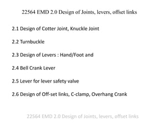
- 1. 22564 EMD 2.0 Design of Joints, levers, offset links 22564 EMD 2.0 Design of Joints, levers, offset links 2.1 Design of Cotter Joint, Knuckle Joint 2.2 Turnbuckle 2.3 Design of Levers : Hand/Foot and 2.4 Bell Crank Lever 2.5 Lever for lever safety valve 2.6 Design of Off-set links, C-clamp, Overhang Crank
- 2. 22564 EMD 2.0 Design of Joints, levers, offset links Revision on Bending Stresses Tension Compression
- 3. 22564 EMD 2.0 Design of Joints, levers, offset links Bending Stress The bending equation is given by where M = Bending moment acting at the given section, σ = Bending stress, I = Moment of inertia of the cross-section about the neutral axis, y = Distance from the neutral axis to the extreme fibre, E = Young’s modulus of the material of the beam, and R = Radius of curvature of the beam. From the above equation, the bending stress is given by The ratio I/y is known as section modulus and is denoted by Z.
- 4. 22564 EMD 2.0 Design of Joints, levers, offset links Section modulus * Ref : Machine Design : R. S. Kurmi
- 5. 22564 EMD 2.0 Design of Joints, levers, offset links Section modulus * Ref : Machine Design : R. S. Kurmi
- 6. 22564 EMD 2.0 Design of Joints, levers, offset links 1) An axle 1 metre long supported in bearings at its ends carries a fly wheel weighing 30 kN at the centre. If the stress (bending) is not to exceed 60 MPa, find the diameter of the axle. Data : L = 1 m = 1000 mm ; F = 30 kN = 30 × 103 N ; σb = 60 MPa = 60 N/mm2 Bending Stress = Given axle is simply supported beam with centrally loading Therfore M = moment can be find
- 7. 22564 EMD 2.0 Design of Joints, levers, offset links F = 30KN centrally loaded and L = 1000mm Consider RA and RB are support reactions at A and B resp. Take moment about A RB x L = F x L/2 RB x 1000 = 30 x 1000 x 1000/2 RB = 15000 N (Reaction at B end) Consider vertical force balance of complete beam F = RA + RB 30000 = RA + 15000 RA = 15000 N A B
- 8. 22564 EMD 2.0 Design of Joints, levers, offset links F = 30000 N, RA = 15000 N, RB = 15000 N Now the maximum moment will be at center of beam where force is acting, therefore, Take moment about center from left or right side Moment M = RA x L/2 (Left) or RB x L/2 (Right) M = 15000 N x 500 mm = 7500000 N-mm It is also known that the moment of simply supported beam centrally loaded is M = F X L / 4 M = 30000 N x 1000 mm / 4 = 7500000 N-mm A B
- 9. 22564 EMD 2.0 Design of Joints, levers, offset links Bending Stress = M = 7500000 N-mm Now Section modulus for circular beam is Z = d3 / 32 Therefore d = 108.3 mm say 110mm
- 10. 22564 EMD 2.0 Design of Joints, levers, offset links 2) A beam of uniform rectangular cross-section is fixed at one end and carries an electric motor weighing 400 N at a distance of 300 mm from the fixed end. The maximum bending stress in the beam is 40 MPa. Find the width and depth of the beam, if depth is twice that of width. Data : F= 400 N ; L = 300 mm ; σb = 40 MPa = 40 N/mm2 ; h = 2b Bending Stress = Moment M = Force x Distance = 400 N x 300 mm = 120000 N-mm
- 11. 22564 EMD 2.0 Design of Joints, levers, offset links Section modulus of rectangular section is h = 2b Therefore b = 16.5 mm h = 2 x b = 2 x 16.5 = 33mm Neutral Axis Tensile stress Compressive stress