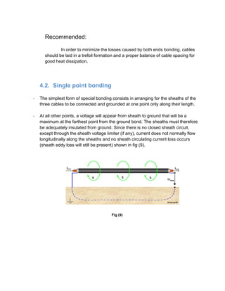
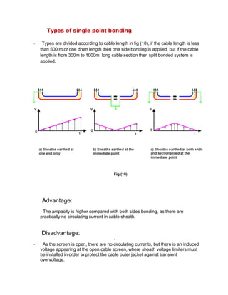
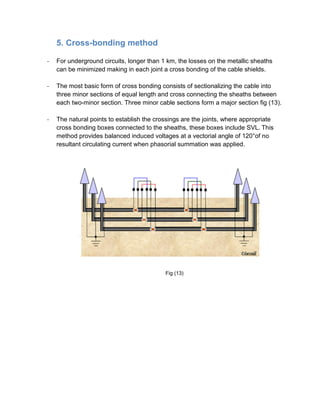
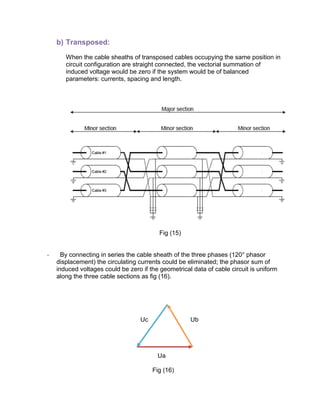
The document discusses sheath bonding methods for underground high voltage (HV) cables, emphasizing the importance of grounding and minimizing losses due to induced voltages in the cable sheaths. It outlines various bonding options, including both ends bonding, single point bonding, and cross-bonding, detailing their advantages and disadvantages as well as their effects on cable ampacity and safety. The latter sections describe specific bonding implementations and the significance of maintaining balanced conditions to reduce circulating currents in the cable sheaths.
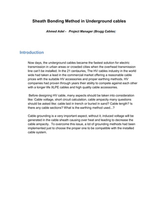


![- Δθ: permissible temperature rise of conductor above ambient temperature.
- Wd: dielectric losses per unit length per phase.
- n: number of conductors in a cable.
- λ1,λ2: ratio of the total losses in metallic sheaths and armour respectively to the
total conductor losses.
- R: alternating current resistance of conductor at its maximum operating
temperature.
- T1: thermal resistance per core between conductor and sheath.
- T2: thermal resistance of between conductor and cable armour.
- T3: thermal resistance of external serving
- T4: thermal resistance of surrounding medium.
By computing Δθ which is the conductor maximum temperature rises above the
ambient temperature:
Δθ = (I²R + ½ Wd) T1 + [I²R (1 + λ1) + Wd] nT2 + [I²R (1+ λ1 + λ2) +
Wd) n (T3 +T4)
However in the case of a simplified cable circuit consisting of single-core cables
(n=1) provided with metallic sheath and no metallic armour (λ2 = 0 and T2 =0) and
ignoring the environmental thermal resistance (T4) the temperature rise between
conductor and cable outer surface is given with the following equation:](https://image.slidesharecdn.com/sheathbondingmethod-170216183250/85/Sheath-bonding-method-for-underground-cables-8-320.jpg)
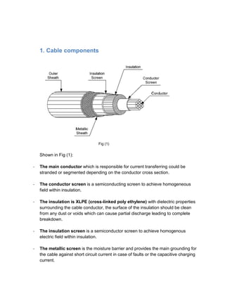
![Δθ = I²R [T1+ T3 (1 + λ1)] + Wd (½T1 +T3)
From the above relation its clear that λ1 (losses generated due to circulating
current) is increasing the temperature rise which will reduce the cable ampacity.
as shown in fig (6) the relation between sheath current and the temperature rise
affecting the cable permissible current.
Fig (6)
Therefore, the sheath circulating current must be reduced for the increment of
transmission capacity. In addition, the high sheath current has an effect on
individuals and may cause the fault by the breakdown of insulation.](https://image.slidesharecdn.com/sheathbondingmethod-170216183250/85/Sheath-bonding-method-for-underground-cables-9-320.jpg)


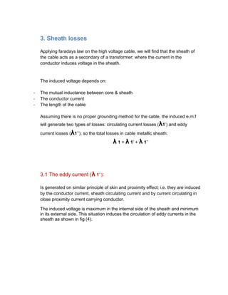
![5.2. CROSS BONDING COMPONENTS
To a cross bonding system implementation the following equipments are applied:
a) Cross bonding boxes to execute the crossing of the sheaths. These boxes
include SVL and each box should have an earth electrode itself for create an
earth return circuit in each divided section of the line. These boxes should be
watertight and capable of containing the effects of the thermal or electrical
failures of any element inside the box, including a possible internal short circuit.
To facilitate its maintenance, these boxes should be installed in joints boxes with
easy access (for example through the placement of manholes) and they should
not be at more than one meter below the ground level [3].
b) Direct bonding boxes to connect the sheath directly to earth. These boxes
include earth electrode but, unlike cross bonding boxes, they do not include SVL.
c) Kits for shield interruption: it is necessary for each phase joint to introduce an
additional kit to remove the shield outside the respective box and to connect a
concentric cable.
d) Cables to the sheaths connection to cross bonding boxes: should be coaxial
cables insulated with XLPE (cross linked polyethylene) or flexible monopole
conductors. The section of these cables is determined by the maximum value of
short circuit current of the power line. Thus, the monopole conductors are directly
connected to the cross bonding boxes. The sheaths connections should be
designed to minimize the cable length, which should not exceed the 10 meters
5.3. Un balanced Conditions
In cross-bonded cable system, there are so many unbalanced conditions. These
unbalanced condition cause circulating current along the metallic sheath. Various
unbalanced conditions are considered:
- Length of minor sections
- Mixed cable arrangement in same major section
- Multiple circuits
- earthing resistance
- etc](https://image.slidesharecdn.com/sheathbondingmethod-170216183250/85/Sheath-bonding-method-for-underground-cables-20-320.jpg)


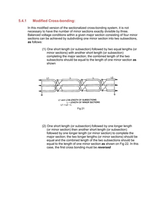
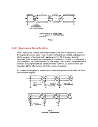
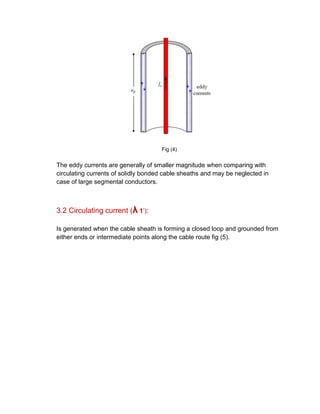
![5.4.3 Mixed Systems.
When the number of minor sections is not exactly divisible by three, the system
may consist of a mixture of (regular or modified) cross-bonded system and
single-point bonded lengths. When necessary, on account of a large number of
minor sections having unequal lengths, the cross bonding may be of the
continuous type. Figure 24 shows the arrangement of a final single point bonded
length at the end of a cross-bonded system.
Fig 24
References:
[1] IEC 287-1-1: “Electric cables-calculation of the current rating, part 1: current rating equations (100%
load factor) and calculation of losses, section 1: general”. IEC publication 287, 1994.
[2] ANSI/IEEE Std 575-1 988, IEEE Guide for the Application of Sheath-Bonding Methods for Single
Conductor Cables and the Calculation of Induced Voltages and Currents in Cable Sheaths.
[3] J.S. Barrett, G.J.Anders. “Circulating current and hysteresis losses in screens, sheaths and armour of
electric power cables-mathematical models and comparison with IEC Standard 287”. IEE Proc.-Sei.
Meas. Technol., Vol. 144, No. 3, pp. 101-110, May 1997
[4] Peter Graneau. “Underground power transmission. The science, technology & economics of high
voltage cables”. Ed. John Wiley & Sons, 1979.
[5] Manuel Llorente Antón. “Cables eléctricos aislados. Descripción y aplicaciones practices”. Editorial
Paraninfo, 1994..](https://image.slidesharecdn.com/sheathbondingmethod-170216183250/85/Sheath-bonding-method-for-underground-cables-25-320.jpg)
![[6] Víctor Sierra Madrigal, Alfonso Sansores Escalante. “Manual técnico de cables de energía”. Ed. Mc
Graw Hill, 2ª Edición, 1984
[7] Enrique Ras. “Teoría de líneas eléctricas”. Ed. Marcombo 1986
[8] Jordi-Roger Riba, Xavier Alabern. “Experimental behavior of a magneticfield shield for an underground
power line”. Internacional Conference on Renewable Energy and Power Quality. Zaragoza, 2005.](https://image.slidesharecdn.com/sheathbondingmethod-170216183250/85/Sheath-bonding-method-for-underground-cables-26-320.jpg)


