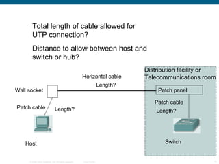
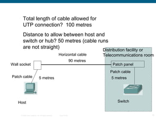
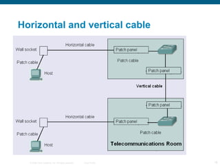
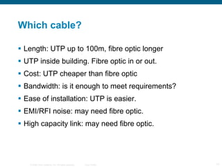
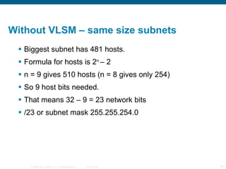
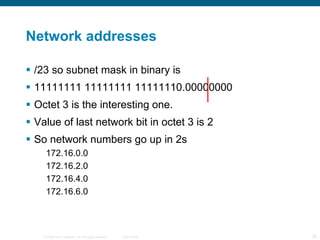
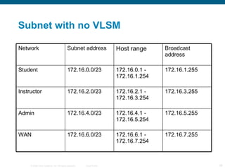
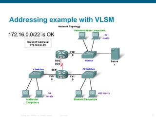
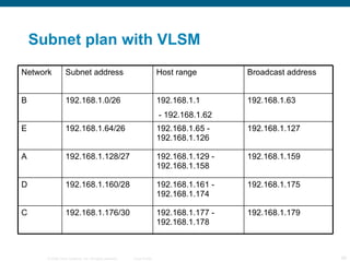
Planning and cabling CCNA Exploration Semester 1  – Chapter 10
Chapter 10 topics Identify media for a LAN. Identify cables, connections and standards for a LAN. Compare straight through and crossover UTP cables Identify cables, connections and standards for a WAN. Make and use a console connection to a Cisco device. Design an addressing scheme for an internetwork.  Compare and contrast network designs.
Within a LAN Hubs and switches link hosts
Between networks Routers link networks together and act as gateways between them.
Hub Frame comes in. Hub regenerates it and forwards it through all ports except incoming port. Shared medium, shared bandwidth. Hosts are in the same collision domain. Cheap. For small LANs only.
Switch Frame comes in. Switch regenerates it and forwards it to destination only. Segments network into separate collision domains. More expensive but better performance than hub
Arranging switches Star for small networks Extended Star for larger networks, perhaps on several floors Mesh to give redundancy – fault tolerance.
Choice of switch ports 10 Mbps? 100 Mbps? 10/100 Mbps?  Problem con longuitud 1Gbps? UTP or fibre optic? Allow for growth. Modular switch? What have our switches got?
Choice of router Expandability – will you want to add extra modules? Media – serial ports, Ethernet ports, UTP or fibre optic, how many of each? Operating System Features – what do you want the router to do? Will you have enough memory to upgrade the operating system? What ports have our routers got?
Router interfaces
Rollover cable - console Our rollover cables a DB9 connector at one end and do not need an adaptor. Rollover cables with RJ45 connectors both ends need an adaptor.
Hyperterminal You run a terminal emulator program such as Hyperterminal on the PC in order to configure the router. Windows has a built in Hyperterminal program. We usually use Hilgraeve Hyperterminal.
Hyperterminal You set up the PC’s serial port as follows: Bits per second: 9600 bps Data bits: 8 Parity: None Stop bits: 1 Flow control: None
Patch panel Wall socket Host Switch Length? Length? Length? Horizontal cable Patch cable Patch cable Total length of cable allowed for UTP connection? Distance to allow between host and switch or hub? Distribution facility or Telecommunications room
Patch panel Wall socket Host Switch 5 metres 5 metres 90 metres Horizontal cable Patch cable Patch cable Total length of cable allowed for UTP connection?  100 metres Distance to allow between host and switch or hub? 50 metres (cable runs are not straight) Distribution facility or Telecommunications room
Horizontal and vertical cable
Which cable? Length: UTP up to 100m, fibre optic longer UTP inside building. Fibre optic in or out. Cost: UTP cheaper than fibre optic Bandwidth: is it enough to meet requirements? Ease of installation: UTP is easier. EMI/RFI noise: may need fibre optic. High capacity link: may need fibre optic.
Attenuation As a signal propagates (travels) it becomes weaker. This is attenuation If a signal becomes too weak then the receiving host cannot tell if it is meant to be a 0 or a 1. This limits cable length.
USB cable reminder Straight through cable – same both ends Crossover cable – 1 swaps with 3, 2 swaps with 6
Why cross over? Transmit needs to connect to receive The crossing over can happen in the cable or inside a device. Transmit Transmit Receive Receive 1 2 3 6
Where is the cross over? Switches and hubs have ports that manage the cross over inside PCs and routers have ports where there is no crossover inside Straight through cable needed if you link a device in one group to a device in the other group Crossover cable needed if you link devices in the same group
Switch ports Most switch ports are normally the MDIX type. They manage the crossing over internally. Some switch ports can be changed between MDI and MDIX either with a switch or in the configuration. Some switches can detect which sort of port is needed and change automatically.
WAN connection Customer’s router Supplier’s device on customer’s premises provides clocking V35 cable or EIA/TIA-232 EIA/TIA-449 X21, V24,  HSSI Supplier’s network
Simulating WAN in the lab
Split network into subnets To cut down the number of broadcasts. Splitting the network into subnets also splits it into separate broadcast domains. To provide different facilities for different groups of users. For security. Traffic between subnets can be controlled.
Addressing the network(s) 1 Start with a topology diagram. All on one network, or will it be split into subnets? How many subnets? How many network bits do we need? n bits can provide 2 n  addresses How many bits are left for hosts?
Addressing the network(s) 2 On each subnet, count the number of: Router interfaces Switches Servers Admin workstations General workstations Printers IP phones
Addressing the network(s) 2 How many host bits do we need? n bits can provide 2 n  addresses One for network, one for broadcast So 2 n  – 2 host addresses. 2 n  – 2 could be 2, 6, 14, 30, 62, 126, 254, 510, 1022, 2046 and so on. Go for a number big enough to give us enough addresses.
How many subnets? Include point to point links.
Bits to borrow n bits borrowed for subnetting gives you 2 n  subnets. So 1 bit gives 2 subnets, 2 bits give 4 subnets, 3 bits give 8 subnets and so on. If you need 5 subnets, how many bits do you borrow? If you need 10 subnets, how many bits do you borrow? 3 4
Addressing example The example given in the curriculum shows subnetting without VLSM using 172.16.0.0/22. (172.16.0.0 – 172.16.3.255) They produce 4 subnets each with 510 addresses. This is  impossible . It will be corrected. You can do it if you start with 172.16.0.0/21 (172.16.0.0 – 172.16.7.255)
Addressing example no VLSM 172.16.0.0/21
What we have and need Given IP address 172.16.0.0/21 That’s 172.16.0.0 to 172.16.7.255 4 subnets needed: Student LAN has  481 hosts Instructor LAN  has  69 hosts Administrator LAN  has  23 hosts WAN has 2 hosts
Without VLSM – same size subnets Biggest subnet has 481 hosts. Formula for hosts is 2 n  – 2 n = 9 gives 510 hosts (n = 8 gives only 254) So 9 host bits needed. That means 32 – 9 = 23 network bits /23 or subnet mask 255.255.254.0
Network addresses /23 so subnet mask in binary is 11111111 11111111 11111110.00000000 Octet 3 is the interesting one. Value of last network bit in octet 3 is 2 So network numbers go up in 2s 172.16.0.0 172.16.2.0 172.16.4.0 172.16.6.0
Subnet with no VLSM Network Subnet address Host range Broadcast address Student 172.16.0.0/23 172.16.0.1 - 172.16.1.254 172.16.1.255 Instructor 172.16.2.0/23 172.16.2.1 - 172.16.3.254 172.16.3.255 Admin 172.16.4.0/23 172.16.4.1 - 172.16.5.254 172.16.5.255 WAN 172.16.6.0/23 172.16.6.1 - 172.16.7.254 172.16.7.255
Addressing example with VLSM 172.16.0.0/22 is OK
What we have and need Given IP address 172.16.0.0/22 That’s 172.16.0.0 to 172.16.3.255 4 subnets needed: Student LAN has  481 hosts Instructor LAN  has  69 hosts Administrator LAN  has  23 hosts WAN has 2 hosts
With VLSM  Student subnet has 481 hosts. Formula for hosts is 2 n  – 2 n = 9 gives 510 hosts (n = 8 gives only 254) So 9 host bits needed. That means 32 – 9 = 23 network bits /23 or subnet mask 255.255.254.0 Network address 172.16.0.0 Broadcast address 172.16.1.255
With VLSM  Instructor subnet has 69 hosts. Formula for hosts is 2 n  – 2 n = 7 gives 126 hosts (n = 6 gives only 62) So 7 host bits needed. That means 32 – 7 = 25 network bits /25 or subnet mask 255.255.255.128 Network address 172.16.2.0 Broadcast address 172.16.2.127
With VLSM  Admin subnet has 23 hosts. Formula for hosts is 2 n  – 2 n = 5 gives 30 hosts (n = 4 gives only 14) So 5 host bits needed. That means 32 – 5 = 27 network bits /27 or subnet mask 255.255.255.224 Network address 172.16.2.128 Broadcast address 172.16.2.159
With VLSM  WAN subnet has 2 hosts. Formula for hosts is 2 n  – 2 n = 2 gives 2 hosts So 2 host bits needed. That means 32 – 2 = 30 network bits /30 or subnet mask 255.255.255.252 Network address 172.16.2.160 Broadcast address 172.16.2.163
Visually with VLSM Student Instructor Admin WAN 172.16.0.0 172.16.1.0 172.16.2.0 172.16.3.0
Case 2. Given 192.168.1.0/24
Subnet 192.168.1.0/24 2 subnets with 28 hosts each (largest) 5 host bits 2 5  - 2 = 30 would be just enough But allow for expansion: 6 host bits give 62 Network bits 32 - 6 = 26  so /26 or subnet mask 255.255.255.192 Network Subnet address Host range Broadcast address B 192.168.1.0/26 192.168.1.1 - 192.168.1.62 192.168.1.63 E 192.168.1.64/26 192.168.1.65 - 192.168.1.126 192.168.1.127
Subnet 192.168.1.1/24 1 subnets with 14 hosts  4 host bits 2 4  - 2 = 14 would be just enough But allow for expansion: 5 host bits give 30 Network bits 32 - 5 = 27  so /27 or subnet mask 255.255.255.224 0-127 range already used Network Subnet address Host range Broadcast address A 192.168.1.128/27 192.168.1.129 - 192.168.1.158 192.168.1.159
Subnet 192.168.1.1/24 1 subnets with 7 hosts  4 host bits 2 4  - 2 = 14 is enough Network bits 32 - 4 = 28  so /28 or subnet mask 255.255.255.240 0-159 range already used Network Subnet address Host range Broadcast address D 192.168.1.160/28 192.168.1.161 - 192.168.1.174 192.168.1.175
Subnet 192.168.1.1/24 1 subnets with 2 hosts  2 host bits 2 2  - 2 = 2 is enough Network bits 32 - 2 = 30  so /30 or subnet mask 255.255.255.252 0-175 range already used Network Subnet address Host range Broadcast address C 192.168.1.176/30 192.168.1.177 - 192.168.1.178 192.168.1.179
Subnet plan with VLSM Network Subnet address Host range Broadcast address B 192.168.1.0/26 192.168.1.1 - 192.168.1.62 192.168.1.63 E 192.168.1.64/26 192.168.1.65 - 192.168.1.126 192.168.1.127 A 192.168.1.128/27 192.168.1.129 - 192.168.1.158 192.168.1.159 D 192.168.1.160/28 192.168.1.161 - 192.168.1.174 192.168.1.175 C 192.168.1.176/30 192.168.1.177 - 192.168.1.178 192.168.1.179
Visual B E A D C One octet available
Summary Hierarchical Design model addresses performance, scalability, maintainability & manageability issues. Traffic Analysis is used to monitor network performance. Hierarchical Design Model is composed of 3 layers: Access Distribution Core Switches selected for each layer must meet the needs of each hierarchical layer as well as the needs of the business.
 

Mod10

  • 1.
    Planning and cablingCCNA Exploration Semester 1 – Chapter 10
  • 2.
    Chapter 10 topicsIdentify media for a LAN. Identify cables, connections and standards for a LAN. Compare straight through and crossover UTP cables Identify cables, connections and standards for a WAN. Make and use a console connection to a Cisco device. Design an addressing scheme for an internetwork. Compare and contrast network designs.
  • 3.
    Within a LANHubs and switches link hosts
  • 4.
    Between networks Routerslink networks together and act as gateways between them.
  • 5.
    Hub Frame comesin. Hub regenerates it and forwards it through all ports except incoming port. Shared medium, shared bandwidth. Hosts are in the same collision domain. Cheap. For small LANs only.
  • 6.
    Switch Frame comesin. Switch regenerates it and forwards it to destination only. Segments network into separate collision domains. More expensive but better performance than hub
  • 7.
    Arranging switches Starfor small networks Extended Star for larger networks, perhaps on several floors Mesh to give redundancy – fault tolerance.
  • 8.
    Choice of switchports 10 Mbps? 100 Mbps? 10/100 Mbps? Problem con longuitud 1Gbps? UTP or fibre optic? Allow for growth. Modular switch? What have our switches got?
  • 9.
    Choice of routerExpandability – will you want to add extra modules? Media – serial ports, Ethernet ports, UTP or fibre optic, how many of each? Operating System Features – what do you want the router to do? Will you have enough memory to upgrade the operating system? What ports have our routers got?
  • 10.
  • 11.
    Rollover cable -console Our rollover cables a DB9 connector at one end and do not need an adaptor. Rollover cables with RJ45 connectors both ends need an adaptor.
  • 12.
    Hyperterminal You runa terminal emulator program such as Hyperterminal on the PC in order to configure the router. Windows has a built in Hyperterminal program. We usually use Hilgraeve Hyperterminal.
  • 13.
    Hyperterminal You setup the PC’s serial port as follows: Bits per second: 9600 bps Data bits: 8 Parity: None Stop bits: 1 Flow control: None
  • 14.
    Patch panel Wallsocket Host Switch Length? Length? Length? Horizontal cable Patch cable Patch cable Total length of cable allowed for UTP connection? Distance to allow between host and switch or hub? Distribution facility or Telecommunications room
  • 15.
    Patch panel Wallsocket Host Switch 5 metres 5 metres 90 metres Horizontal cable Patch cable Patch cable Total length of cable allowed for UTP connection? 100 metres Distance to allow between host and switch or hub? 50 metres (cable runs are not straight) Distribution facility or Telecommunications room
  • 16.
  • 17.
    Which cable? Length:UTP up to 100m, fibre optic longer UTP inside building. Fibre optic in or out. Cost: UTP cheaper than fibre optic Bandwidth: is it enough to meet requirements? Ease of installation: UTP is easier. EMI/RFI noise: may need fibre optic. High capacity link: may need fibre optic.
  • 18.
    Attenuation As asignal propagates (travels) it becomes weaker. This is attenuation If a signal becomes too weak then the receiving host cannot tell if it is meant to be a 0 or a 1. This limits cable length.
  • 19.
    USB cable reminderStraight through cable – same both ends Crossover cable – 1 swaps with 3, 2 swaps with 6
  • 20.
    Why cross over?Transmit needs to connect to receive The crossing over can happen in the cable or inside a device. Transmit Transmit Receive Receive 1 2 3 6
  • 21.
    Where is thecross over? Switches and hubs have ports that manage the cross over inside PCs and routers have ports where there is no crossover inside Straight through cable needed if you link a device in one group to a device in the other group Crossover cable needed if you link devices in the same group
  • 22.
    Switch ports Mostswitch ports are normally the MDIX type. They manage the crossing over internally. Some switch ports can be changed between MDI and MDIX either with a switch or in the configuration. Some switches can detect which sort of port is needed and change automatically.
  • 23.
    WAN connection Customer’srouter Supplier’s device on customer’s premises provides clocking V35 cable or EIA/TIA-232 EIA/TIA-449 X21, V24, HSSI Supplier’s network
  • 24.
  • 25.
    Split network intosubnets To cut down the number of broadcasts. Splitting the network into subnets also splits it into separate broadcast domains. To provide different facilities for different groups of users. For security. Traffic between subnets can be controlled.
  • 26.
    Addressing the network(s)1 Start with a topology diagram. All on one network, or will it be split into subnets? How many subnets? How many network bits do we need? n bits can provide 2 n addresses How many bits are left for hosts?
  • 27.
    Addressing the network(s)2 On each subnet, count the number of: Router interfaces Switches Servers Admin workstations General workstations Printers IP phones
  • 28.
    Addressing the network(s)2 How many host bits do we need? n bits can provide 2 n addresses One for network, one for broadcast So 2 n – 2 host addresses. 2 n – 2 could be 2, 6, 14, 30, 62, 126, 254, 510, 1022, 2046 and so on. Go for a number big enough to give us enough addresses.
  • 29.
    How many subnets?Include point to point links.
  • 30.
    Bits to borrown bits borrowed for subnetting gives you 2 n subnets. So 1 bit gives 2 subnets, 2 bits give 4 subnets, 3 bits give 8 subnets and so on. If you need 5 subnets, how many bits do you borrow? If you need 10 subnets, how many bits do you borrow? 3 4
  • 31.
    Addressing example Theexample given in the curriculum shows subnetting without VLSM using 172.16.0.0/22. (172.16.0.0 – 172.16.3.255) They produce 4 subnets each with 510 addresses. This is impossible . It will be corrected. You can do it if you start with 172.16.0.0/21 (172.16.0.0 – 172.16.7.255)
  • 32.
    Addressing example noVLSM 172.16.0.0/21
  • 33.
    What we haveand need Given IP address 172.16.0.0/21 That’s 172.16.0.0 to 172.16.7.255 4 subnets needed: Student LAN has 481 hosts Instructor LAN has 69 hosts Administrator LAN has 23 hosts WAN has 2 hosts
  • 34.
    Without VLSM –same size subnets Biggest subnet has 481 hosts. Formula for hosts is 2 n – 2 n = 9 gives 510 hosts (n = 8 gives only 254) So 9 host bits needed. That means 32 – 9 = 23 network bits /23 or subnet mask 255.255.254.0
  • 35.
    Network addresses /23so subnet mask in binary is 11111111 11111111 11111110.00000000 Octet 3 is the interesting one. Value of last network bit in octet 3 is 2 So network numbers go up in 2s 172.16.0.0 172.16.2.0 172.16.4.0 172.16.6.0
  • 36.
    Subnet with noVLSM Network Subnet address Host range Broadcast address Student 172.16.0.0/23 172.16.0.1 - 172.16.1.254 172.16.1.255 Instructor 172.16.2.0/23 172.16.2.1 - 172.16.3.254 172.16.3.255 Admin 172.16.4.0/23 172.16.4.1 - 172.16.5.254 172.16.5.255 WAN 172.16.6.0/23 172.16.6.1 - 172.16.7.254 172.16.7.255
  • 37.
    Addressing example withVLSM 172.16.0.0/22 is OK
  • 38.
    What we haveand need Given IP address 172.16.0.0/22 That’s 172.16.0.0 to 172.16.3.255 4 subnets needed: Student LAN has 481 hosts Instructor LAN has 69 hosts Administrator LAN has 23 hosts WAN has 2 hosts
  • 39.
    With VLSM Student subnet has 481 hosts. Formula for hosts is 2 n – 2 n = 9 gives 510 hosts (n = 8 gives only 254) So 9 host bits needed. That means 32 – 9 = 23 network bits /23 or subnet mask 255.255.254.0 Network address 172.16.0.0 Broadcast address 172.16.1.255
  • 40.
    With VLSM Instructor subnet has 69 hosts. Formula for hosts is 2 n – 2 n = 7 gives 126 hosts (n = 6 gives only 62) So 7 host bits needed. That means 32 – 7 = 25 network bits /25 or subnet mask 255.255.255.128 Network address 172.16.2.0 Broadcast address 172.16.2.127
  • 41.
    With VLSM Admin subnet has 23 hosts. Formula for hosts is 2 n – 2 n = 5 gives 30 hosts (n = 4 gives only 14) So 5 host bits needed. That means 32 – 5 = 27 network bits /27 or subnet mask 255.255.255.224 Network address 172.16.2.128 Broadcast address 172.16.2.159
  • 42.
    With VLSM WAN subnet has 2 hosts. Formula for hosts is 2 n – 2 n = 2 gives 2 hosts So 2 host bits needed. That means 32 – 2 = 30 network bits /30 or subnet mask 255.255.255.252 Network address 172.16.2.160 Broadcast address 172.16.2.163
  • 43.
    Visually with VLSMStudent Instructor Admin WAN 172.16.0.0 172.16.1.0 172.16.2.0 172.16.3.0
  • 44.
    Case 2. Given192.168.1.0/24
  • 45.
    Subnet 192.168.1.0/24 2subnets with 28 hosts each (largest) 5 host bits 2 5 - 2 = 30 would be just enough But allow for expansion: 6 host bits give 62 Network bits 32 - 6 = 26 so /26 or subnet mask 255.255.255.192 Network Subnet address Host range Broadcast address B 192.168.1.0/26 192.168.1.1 - 192.168.1.62 192.168.1.63 E 192.168.1.64/26 192.168.1.65 - 192.168.1.126 192.168.1.127
  • 46.
    Subnet 192.168.1.1/24 1subnets with 14 hosts 4 host bits 2 4 - 2 = 14 would be just enough But allow for expansion: 5 host bits give 30 Network bits 32 - 5 = 27 so /27 or subnet mask 255.255.255.224 0-127 range already used Network Subnet address Host range Broadcast address A 192.168.1.128/27 192.168.1.129 - 192.168.1.158 192.168.1.159
  • 47.
    Subnet 192.168.1.1/24 1subnets with 7 hosts 4 host bits 2 4 - 2 = 14 is enough Network bits 32 - 4 = 28 so /28 or subnet mask 255.255.255.240 0-159 range already used Network Subnet address Host range Broadcast address D 192.168.1.160/28 192.168.1.161 - 192.168.1.174 192.168.1.175
  • 48.
    Subnet 192.168.1.1/24 1subnets with 2 hosts 2 host bits 2 2 - 2 = 2 is enough Network bits 32 - 2 = 30 so /30 or subnet mask 255.255.255.252 0-175 range already used Network Subnet address Host range Broadcast address C 192.168.1.176/30 192.168.1.177 - 192.168.1.178 192.168.1.179
  • 49.
    Subnet plan withVLSM Network Subnet address Host range Broadcast address B 192.168.1.0/26 192.168.1.1 - 192.168.1.62 192.168.1.63 E 192.168.1.64/26 192.168.1.65 - 192.168.1.126 192.168.1.127 A 192.168.1.128/27 192.168.1.129 - 192.168.1.158 192.168.1.159 D 192.168.1.160/28 192.168.1.161 - 192.168.1.174 192.168.1.175 C 192.168.1.176/30 192.168.1.177 - 192.168.1.178 192.168.1.179
  • 50.
    Visual B EA D C One octet available
  • 51.
    Summary Hierarchical Designmodel addresses performance, scalability, maintainability & manageability issues. Traffic Analysis is used to monitor network performance. Hierarchical Design Model is composed of 3 layers: Access Distribution Core Switches selected for each layer must meet the needs of each hierarchical layer as well as the needs of the business.
  • 52.