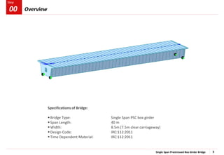
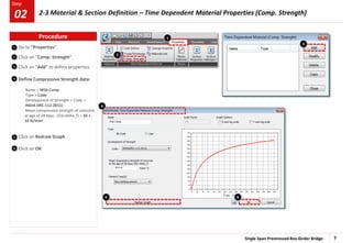
This document is a tutorial for creating a single-span prestressed post-tensioned box girder bridge using MIDAS Civil software. It covers various stages, including material and section definitions, geometric modeling, analysis control, and interpreting results, all based on the guidelines set by IRC codes. The tutorial includes step-by-step instructions for modeling, loading, analyzing, and designing the bridge components.


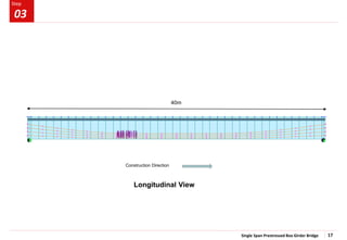
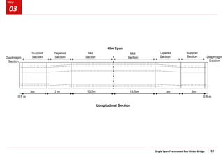
![Single Span Prestressed Box Girder Bridge 4
Step
Step
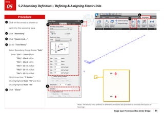
Invoke midas Civil
Open New File
Select the Unit System [ kN, m]
Save as ‘Single Span PSC Box Girder’
1
2
3
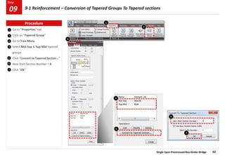
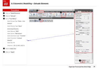
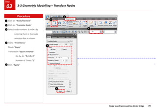
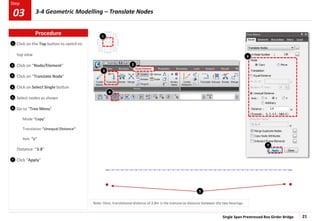
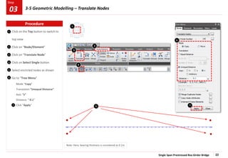
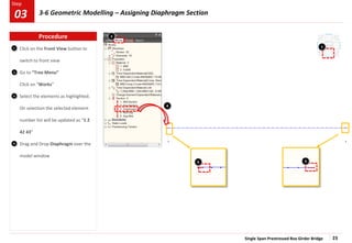
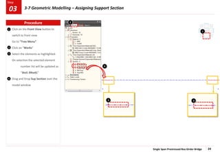
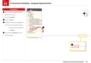
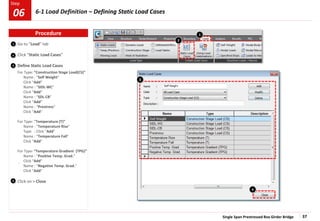
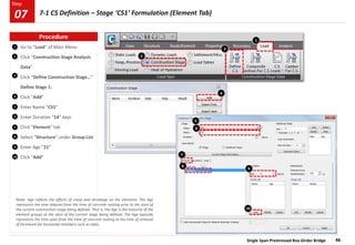
Procedure
.
3
2
1 Initial Setting
01
1](https://image.slidesharecdn.com/3pscboxbridgesinglespan-241018000504-50a634e5/85/PSC-Box-Bridge-Single-Span-for-structural-engineers-4-320.jpg)
![Single Span Prestressed Box Girder Bridge 6
Step
Step
1
2
3
4
5
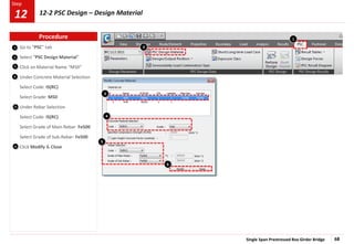
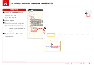
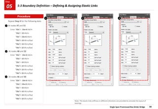
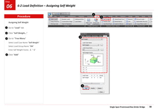
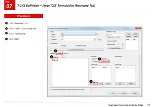
Change unit system [ N, mm ]
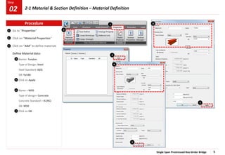
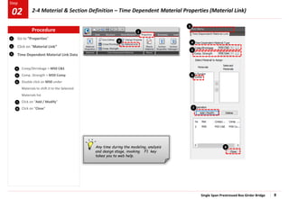
Go to “Properties”
(Creep/Shrinkage)”
Click on “Add” to define properties
Define Creep / Shrinkage data:
Name > M50 C&S
Code > INDIA (IRC:112-2011)
Compressive strength of concrete at
the age of 28 days > 50 N/mm2
Relative Humidity of ambient
environment (40–99) > 70
Notational size of member > 1000mm
Age of concrete at the beginning of
shrinkage > 3 days
Click on Show Result to see the graph
Click on OK to add the C&S property.
7
6
2
3
4
6 7
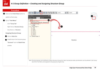
Note: To get the creep & shrinkage strains, the value of relative humidity is to be considered as 70%, Notational size of member, h as
1000mm and Age of concrete at the beginning of shrinkage as 3 days. Later, the h value would be automatically updated for
composite sections
1
5
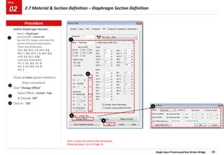
Procedure
02 2-2 Material & Section Definition – Time Dependent Material Properties (Creep &Shrinkage)](https://image.slidesharecdn.com/3pscboxbridgesinglespan-241018000504-50a634e5/85/PSC-Box-Bridge-Single-Span-for-structural-engineers-6-320.jpg)
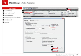
![Single Span Prestressed Box Girder Bridge 10
Step
Step
1
2
4
5
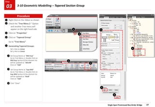
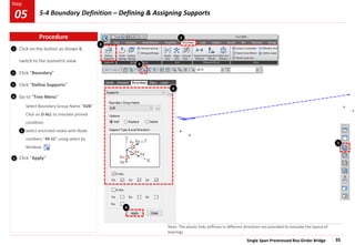
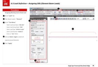
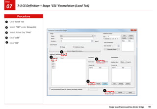
Change unit system [ KN, m ]
Go to “Properties” > Section
Properties”
Click on “Add..”
Click on tab “PSC”
Select: ‘PSC-1Cell, 2Cell’ type
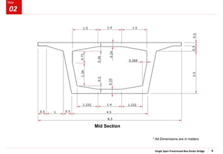
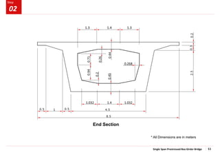
Define Mid Section:
Name > Mid Section
Joint On/Off > Check JO1, JI1, JI3, JI5
See the PSC Viewer and enter the
section dimension parameters
Outer box dimensions
HO1: 0.2, BO1: 1.5, HO2: 0.3,
BO1-1: 0.5, HO2-1: 0, BO2: 0.5,
HO3: 2.5, BO3: 2.25
Inner box dimensions
HI1: 0.24, BI1: 2.2, HI2: 0.26,
BI1-1: 0.7, HI2-1: 0, BI2-1: 2.2
HI3: 2.05, BI3: 1.932, HI3-1: 0.71,
BI3-1: 0.7, HI4: 0.2, HI4-1: 0,
HI5: 0.25
Check all Auto options related to
Shear calculations
Click “Change Offset”
Select Offset : Center- Top
& Click on “OK”
3
Note: The internal Process of section offset is explained in the help file .
Path: Help > Contents > Start > Model > Properties > Section, When Section
tab is opened under offset, click on ‘Details’
6
8
7
2
4
9
1
Click “Show Calculation Results”
Click on “Apply”
10
5
3
6
10
8
7
9
8
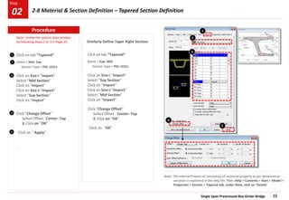
Procedure
02 2-5 Material & Section Definition – Mid Section Definition](https://image.slidesharecdn.com/3pscboxbridgesinglespan-241018000504-50a634e5/85/PSC-Box-Bridge-Single-Span-for-structural-engineers-10-320.jpg)
![Single Span Prestressed Box Girder Bridge 41
Step
Step
1
2
3
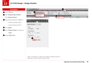
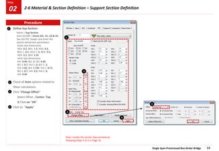
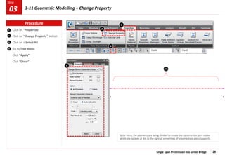
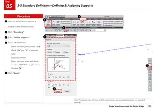
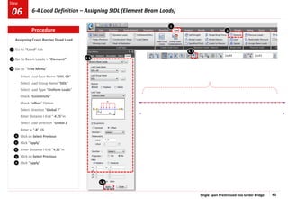
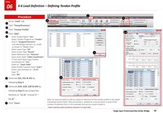
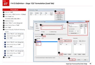
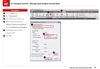
Change unit system [N,mm]
Go to “Load” of Main Menu
Click “Temp/Prestress”
Click “Tendon Property”
Click “Add”
Enter Tendon Name “Tendon”
Select Tendon Type “Internal(Post-
Tension”
Select Material “Tendon”
Click “…” in the dialog box for Total
Tendon Area
Select Strand Diameter
“15.2mm(0.6”)”
Enter Number of Strands “19”
Click “OK”
Enter Duct Diameter “110”mm
Select Relaxation Coefficient “India
(IRC:112-2011) – Low”
Enter Ultimate Strength “1860”
Enter Yield Strength “1581”
Enter Curvature Friction Factor
“0.17”
Enter Wobble Friction Factor as
“2e-6”/mm
Enter Anchorage Slip Begin : “6”
Enter Anchorage Slip End : “6”
Select Bond Type “Bonded”
Click “OK”
Click “Close”
4
2
3
1
4
5
7
7
5
6
6
Procedure
6-5 Load Definition – Defining Tendon Property
06](https://image.slidesharecdn.com/3pscboxbridgesinglespan-241018000504-50a634e5/85/PSC-Box-Bridge-Single-Span-for-structural-engineers-41-320.jpg)
![Single Span Prestressed Box Girder Bridge 52
Step
Step
3
1
2
3
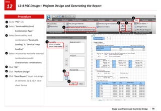
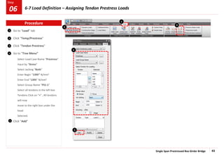
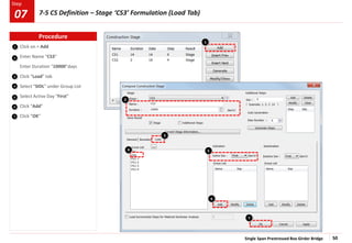
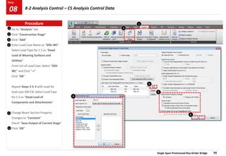
Go to “Load” tab
Click “Temp/Prestress”
Click “Beam Section Temp.”
Select all superstructure elements.
Go to “Tree menu”
Select Load Case name as “Positive
Temp. Grad.”
Section Type > PSC/Composite
Select “Element” option for Material
Keep Ref. as “Top”
B > “Section”
Enter H1 as 0 mm
Enter H2 as 150 mm
Enter T1 as 17.8 [C]
Enter T2 as 4 [C]
Click on Add
Change Parameters:
Enter H1 as 150 mm
Enter H2 as 400 mm
Enter T1 as 4 [C]
Enter T2 as 0 [C]
Click on Add
Change Parameters:
Enter H1 as 2850 mm
Enter H2 as 3000 mm
Enter T1 as 0 [C]
Enter T2 as 2.1 [C]
Click on Add
Click “Apply”
4
5
If temperature units are in degree Fahrenheit, one can change to degree Celsius from Tools Unit System
6
6
h1 = 0.15m
h2 = 0.25m
h3 = 0.15m
Positive Temperature
Differences
Reverse Temperature
Differences
h1
h2
h3
h1
h2
h3
h4
h1 = h4 = 0.25m
h2 = h3 = 0.25m
For the given depth of box girder
4
2 5
1
Procedure
6-10 Load Definition – Assigning Positive Temperature Differences (Beam Section Temperature)
06](https://image.slidesharecdn.com/3pscboxbridgesinglespan-241018000504-50a634e5/85/PSC-Box-Bridge-Single-Span-for-structural-engineers-52-320.jpg)
![Single Span Prestressed Box Girder Bridge 53
Step
Step
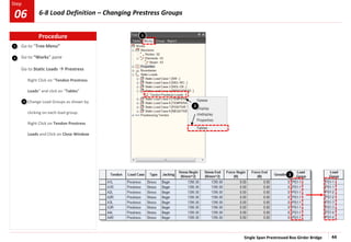
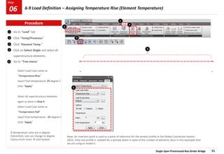
Change Parameters:
Enter H1 as 2750 mm
Enter H2 as 3000 mm
Enter T1 as -0.8 [C]
Enter T2 as -6.6 [C]
Click “Apply”
1
2
3
Go to “Load” tab
Click “Temp/Prestress”
Click “Beam Section Temp.”
Select all superstructure elements.
Go to “Tree menu”
Select Load Case name as “Negative
Temp. Grad.”
Section Type > PSC/Composite
Select “Element” option for Material
Keep Ref. as “Top”
B > “Section”
Enter H1 as 0 mm
Enter H2 as 250 mm
Enter T1 as -10.3 [C]
Enter T2 as -0.7 [C]
Click on Add
Change Parameters:
Enter H1 as 250 mm
Enter H2 as 500 mm
Enter T1 as -0.7 [C]
Enter T2 as 0 [C]
Click on Add
Change Parameters:
Enter H1 as 2500 mm
Enter H2 as 2750 mm
Enter T1 as 0 [C]
Enter T2 as -0.8 [C]
Click on Add
4
5
Note: An insertion point is used as a point of reference for the tendon profile in the Global Coordinate System (GCS).
Only one profile is needed for a precast beam in spite of the number of elements (four in this example) that we are
using to model it.
6 6
4
3
2
1
5
Procedure
6-11 Load Definition – Assigning Negative Temperature Differences (Beam Section Temperature)
06](https://image.slidesharecdn.com/3pscboxbridgesinglespan-241018000504-50a634e5/85/PSC-Box-Bridge-Single-Span-for-structural-engineers-53-320.jpg)
![Single Span Prestressed Box Girder Bridge 54
Step
Step
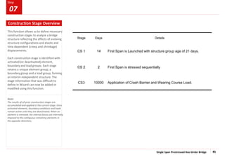
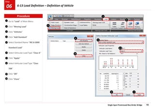
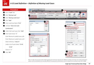
Change unit system [kN , m]
Go to “Load” tab
Click “Moving Load”
Moving Load Code > India
Click “Traffic Line Lanes”
Click “Add”
Enter Lane Name “70R”
View the figure provided
Enter Eccentricity “1.155”m
Enter Wheel Spacing “1.93”m
Enter Impact factor “0.1”
Select Vehicular Load Distribution as
“Lane Element”
Select Moving direction as “Both”
Select Selection by “2 Points”
Click in the “Box”
Click on extreme left node of
superstructure i.e. node no. 1
Click on extreme right node of
superstructure i.e. node no. 44
Click “OK”
3
7
1
Node: 1 Node: 44
6
6
7
1
2
3
4
5
2
Procedure
6-12 Load Definition – Definition of Traffic Line Lanes
06
5 6
For other lanes, similarly change names,
wheel spacing and eccentricities as
below:
Enter Lane Name “Cl.A 1”
Enter Eccentricity “2.45”m
Enter Wheel Spacing “1.8”m
Enter Impact factor “0.1”
Enter Lane Name “Cl.A 2”
Enter Eccentricity “-1.05”m
Enter Wheel Spacing “1.8”m
Enter Impact factor “0.1”
4](https://image.slidesharecdn.com/3pscboxbridgesinglespan-241018000504-50a634e5/85/PSC-Box-Bridge-Single-Span-for-structural-engineers-54-320.jpg)
![Single Span Prestressed Box Girder Bridge 61
Step
Step
1
2
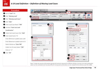
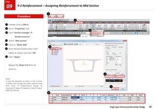
Select “Mid section”
Click on “Shear Reinforcement”
Enter Shear Reinforcement data
under “Diagonal Reinforcement” as
Pitch: 0.15m
Angle: 90 [deg]
Aw: 0.0012568 m^2 (4Legs of P20)
Enter Torsional Reinforcement data
under “Torsional Reinforcement” as
Pitch: 0.15m
Awt: 0.0003142 m^2 (1Leg of P20)
Alt: 0.008044 m^2(40 Nos. of P16)
Click “Apply”
Repeat the Steps 2 to 5 for all
sections.
Click “Close”
3
1
4
2
5
3
4
7
5
6
*Note: Diameter & number of rebars can be entered by clicking …
*
*
*
Procedure
9-3 Reinforcement – Assigning Reinforcement to Mid Section
09
7](https://image.slidesharecdn.com/3pscboxbridgesinglespan-241018000504-50a634e5/85/PSC-Box-Bridge-Single-Span-for-structural-engineers-61-320.jpg)