Structural Analysis and Design of Foundations: A Comprehensive Handbook for S...
Archive for the ‘refrigerator commissioning’ tag
1. Archive for the ‘Refrigerator Commissioning’ tag
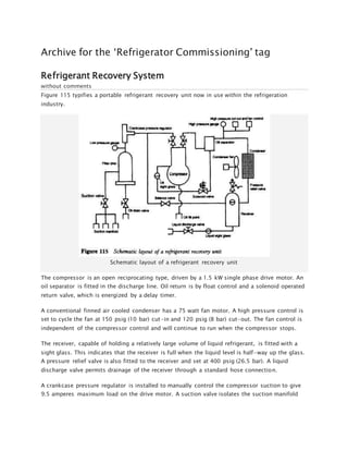
Refrigerant Recovery System
without comments
Figure 115 typifies a portable refrigerant recovery unit now in use within the refrigeration
industry.
Schematic layout of a refrigerant recovery unit
The compressor is an open reciprocating type, driven by a 1.5 kW single phase drive motor. An
oil separator is fitted in the discharge line. Oil return is by float control and a solenoid operated
return valve, which is energized by a delay timer.
A conventional finned air cooled condenser has a 75 watt fan motor. A high pressure control is
set to cycle the fan at 150 psig (10 bar) cut-in and 120 psig (8 bar) cut-out. The fan control is
independent of the compressor control and will continue to run when the compressor stops.
The receiver, capable of holding a relatively large volume of liquid refrigerant, is fitted with a
sight glass. This indicates that the receiver is full when the liquid level is half-way up the glass.
A pressure relief valve is also fitted to the receiver and set at 400 psig (26.5 bar). A liquid
discharge valve permits drainage of the receiver through a standard hose connection.
A crankcase pressure regulator is installed to manually control the compressor suction to give
9.5 amperes maximum load on the drive motor. A suction valve isolates the suction manifold
2. from the recovery unit. The manifold has three hose unions for multiple connection to various
parts of the system from which the refrigerant is to be recovered.
A balance valve connected to both the high and the low sides of the system can be opened to
allow:
1. The unit to be operated on a simulated load in order to set the motor load current.
2. The compressor to be started unloaded.
3. Ease of unit evacuation when changing refrigerants.
4. Manual air purging.
Standard glycerine dampened compound and pressure gauges measure the system pressures.
A suction filter drier contains a burn-out core, and acts as a suction boiloff reservoir should
small amounts of liquid refrigerant be passed through the unit. It also allows any oil removed
from the refrigerant to be drained via a suction filter drain valve with a standard hose
connection.
Written by sam
November 12th, 2009 at 8:51 pm
Posted in Commissioning of refrigerating systems
Tagged with Refrigerant recovery system, Refrigerator Commissioning
Good refrigeration practice for CFC systems
without comments
It is a well known fact that an engineer required to work on an ammonia system will be very
careful not to allow undue discharges of refrigerant because of its toxicity. Since CFCs are non-
toxic it has been common practice to discharge them to atmosphere. This must now be
regarded as malpractice and cease forthwith.
Evacuation
It was also past practice to use the dilution or triple evacuation method, in which a small
amount of refrigerant is used to dilute the atmosphere within the system, discharging between
evacuations. This method can still be employed, but instead of releasing the refrigerant to
atmosphere it should be reclaimed by decanting to a cooled refrigerant cylinder.
Alternatively, the more practical deep evacuation method should be adopted.
Cleaning condensers
The practice of cleaning condensers with a refrigerant should be discontinued. Proprietary
brands of degreasing and cleansing agents which are environment friendly are readily available.
Should it be necessary to apply pressure to ensure penetration to fins and pipework, then
nitrogen should be used.
3. Decanting refrigerant
Special care must be taken not to overfill the cylinder, and to use only those which are free from
any contamination by oil, acid or moisture.
Do not mix grades of refrigerants. Always use a cylinder for the specific refrigerant for which it
is designated.
Removal of refrigerant from sealed systems
This can be achieved by fitting a line tap valve to the system and connecting to a recovery
cylinder.
Removal of contaminated refrigerant
Contaminated refrigerant which may have resulted from a compressor burnout or a water
cooled condenser leak must not be used to recharge the system. It must be recovered and sent
away for reprocessing or disposal.
It should be decanted into special recovery cylinders available from the manufacturers or
suppliers of refrigerants. Never use service cylinders for reclaiming contaminated refrigerants.
When removing refrigerant charges or decanting from systems, adequate protective clothing
and goggles must be worn. All safety procedures must be observed.
It is advisable to include an isolating hand shut-off valve at the cylinder end of the charging line
to minimize purging. Ensure that the valve is open before discharging from the system. Use
charging lines without the Schreader inserts.
Written by sam
November 12th, 2009 at 8:48 pm
Posted in Commissioning of refrigerating systems
Tagged with Refrigerator Commissioning
Environmental impact of CFCs
with one comment
Chlorofluorocarbons (CFCs) are chemical compounds which have been developed for use as
refrigerants. Their molecular structure is based on either methane or ethane; one or more of
the hydrogen atoms is substituted by chlorine or fluorine.
The CFC refrigerants soon replaced most other refrigerants except ammonia, which is still in
use today. Other products made from CFCs were then used for aerosols, expanded foam
processes and degreasing agents.
of refrigerants is their chemical stability. It is this long term stability which contributes to the
pollution of the atmosphere. Once released, CFCs remain in the atmosphere for years. At low
altitudes this does not present a problem. However, when they reach the upper atmosphere
4. CFCs, like ozone, are broken down by ultraviolet light. This results in the release of free radical
chlorine atoms, which interfere with the normal formation of ozone and contribute to the
greenhouse effect (about 10-15 per cent).
There are now restrictions imposed upon manufacturers of certain CFCs by the Montreal
Protocol, an international agreement which came into force in January 1989. Within ten years,
production of CFCs should have been reduced to 50 per cent of the 1986 levels.
Refrigeration service and installation engineers can assist in reducing the emission of CFCs.
Design engineers can ensure that systems are constructed so that emissions are minimal when
various forms of maintenance or repairs are necessary.
Written by sam
November 12th, 2009 at 8:44 pm
Posted in Commissioning of refrigerating systems
Tagged with Environmental impact of CFCs, Refrigerator Commissioning
Refrigerator Oil Addition and Removal
without comments
When the system has been fully charged and the controls set, the equipment is operated at
average evaporating conditions. The compressor oil level must then be checked.
All new compressors receive an operating oil charge during manufacture, but this does not
allow for oil trapped within components and controls and circulating with the refrigerant. This
is the reason why oil levels must be checked and oil added to the system at the time of
installation or commissioning.
Adding oil
Only the make and grade of oil specified by the manufacturer of the compressor must be used.
Oils have special characteristics for pressure, temperature and load conditions, especially those
used for low temperature applications.
The larger compressors will have oil-level-indicating sight glasses located in the crankcase. If
compressors are used in parallel, there is sometimes a sight glass in the middle of the oil
equalizer line. During operation the oil level in the crankcase may well fluctuate. It is generally
accepted that a level maintained at one-third to one-half of the way up the sight glass is
satisfactory.
Before any oil is added, the system must be fully charged. This is most important when the
compressor is located above the level of the evaporator. Oil levels should be rechecked after a
system has completed its initial pulldown, or has operated for at least two hours. If a sight
glass indicates foaming, ensure that this is not the result of absorbed refrigerant. Systems
prone to this condition will probably be fitted with crankcase heaters.
5. Oil may be added to the crankcase of larger compressors simply by pumping down and
reducing the crankcase pressure to enable oil to be poured when the filler cap has been
removed. However, filler holes tend to be small on some compressors and an oil pump may be
used.
Too much oil in a crankcase can cause damage to a compressor by creating a dynamic pressure
during operation.
The procedures for adding oil will obviously vary according to the type of compressor.
Charging pump and simple filling
The oil charging pump is similar to a cycle pump and needs no explanation. The correct oil
level must be attained, and reference should be made to the manufacturer’s data.
Sometimes it suffices to add oil to a compressor until it runs out of the filler hole; a dipstick will
be required for other types. In each instance the oil level will be such that it is approximately 25
mm (1 inch) below the crankshaft so that bearings or splashers immerse in the oil as the shaft
rotates (Figure 110).
Vacuum pump
When a compressor has a sight glass it is a simple task to add oil. The procedure is as follows
(Figure 111):
1. Pump down the system to reduce the pressure in the crankcase to 0.1 bar (1 psig) and front
seat both suction and discharge service valves.
2. Remove the oil filler plug and fit a charging line incorporating a shut-off valve and an
adaptor to insert into the filler hole.
3. Place the free end of the charging line into a container of clean and uncontaminated oil from
a sealed can. Crack off the suction service valve from the front seat position and raise the
crankcase pressure to 0.1 bar.
6. Open the shut-off valve slowly and purge the charging line through the oil in the container.
Front seat the suction service valve.
4. Connect a vacuum pump to the gauge union of the suction service valve. 5 Switch on the
vacuum pump and reduce the pressure in the crankcase to slightly below atmospheric, allowing
the oil to be drawn in until the correct level is reached.
6. Stop the vacuum pump, crack off the suction service valve from the front seat position, purge
oil from the charging line and close the shut-off valve. Then front seat the suction service valve.
7. Remove the charging line and replace the oil filler plug.
8. Fully back seat and crack off both service valves, or set to operating positions.
9 Leak test the compressor.
10 Start the system and allow it to settle down to average operating conditions. echeck the oil
level.
When charging oil, ensure that the charging line is always below the oil level in the container.
Compressor charging
When the compressor design is such that a suction strainer and oil return to the crankcase is
featured, oil may be added via the suction service valve gauge union in much the same way as
described above but using the compressor to draw a vacuum instead of a vacuum pump (Figure
112).
7. Draining compressor oil
This may be necessary when too much oil has been added, when maintenance contracts
stipulate a periodic oil change, or when a system has been contaminated.
Assuming that the compressor does not have an oil drain facility and the removal of the base
plate or sump plate is impractical or uneconomical, two simple methods may be adopted.
Vacuum method
This requires an air tight container or preferably a graduated cylinder so that the amount of oil
removed can be measured and the precise amount replaced.
By pulling a vacuum on the container or cylinder, the oil will be drawn out of the compressor
into the cylinder (Figure 113). During this process the compressor must be isolated from the
system by front seating the service valves.
System pressure method
With a length of tubing and an adaptor fitted to the filler hole after pressure in the crankcase
has been reduced and both service valves front seated, create a positive pressure in the
crankcase by cracking off the suction service valve from the front seat position (Figure 114).
8. Provided the tubing reaches to the bottom of the crankcase or sump, the oil will be forced out
of the compressor and into the container.
Correcting the oil level
The pressure method above can be used to reduce the level of oil in the crankcase in the event
of an overcharge. By fitting an adaptor tube which terminates at the correct level below the
crankshaft, oil will be forced out of the compressor when the crankcase is pressurized, but only
until the oil level reaches the end of the tube.
Written by sam
November 12th, 2009 at 8:36 pm
Posted in Commissioning of refrigerating systems
Tagged with Oil addition and removal, Refrigerator Commissioning, Refrigerator Repair, Refrigerator
Troubleshooting
Refrigerator Commissioning Checks
without comments
When the system has been evacuated, the next step is to carry out a thorough leak test.
The system may then be charged with refrigerant. Irrespective of which method of charging is
used, it must be remembered that the compressor is being operated for the first time. It will
have been standing for a considerable period, and oil will have drained from cylinders and
bearings.
Before attempting to start the compressor the following checks must be made:
1. Ensure that the electrical supply voltage is correct according to the compressor motor
nameplate.
2. Check the voltage at the compressor motor terminals.
3. Check the fuse ratings.
4. Set the safety controls and check operation.
5. If the compressor is an open type, turn it over by hand if this is practical to verify free
rotation.
9. At this stage it is also advisable to prepare an equipment log and to record electrical data,
control settings, operating pressures and temperatures noted during commissioning, in case of
a break in continuity during this procedure and for future reference.
Written by sam
November 12th, 2009 at 8:28 pm
Posted in Commissioning of refrigerating systems
Tagged with Commissioning checks, Refrigerator Commissioning
Refrigerator Evacuation
without comments
It is imperative, with halogen refrigeration systems, that all traces of air, non-condensibles and
moisture be removed. If this is not achieved then the presence of air or non-condensibles will
cause abnormally high discharge pressures and increased temperatures, resulting in the
conditions relating to high operating pressures previously explained.
Air in the system will also mean that a certain amount of moisture contained in the air will be
circulated with the refrigerant under operating conditions. This moisture could freeze at the
orifice of an expansion valve or liquid capillary to prevent refrigerant flow to the evaporator,
should the filter drier become saturated.
When a system has been pressure leak tested, traces of nitrogen may also be present to further
aggravate the high discharge pressure condition.
There are two ways in which a system can be evacuated, the deep vacuum method and the
dilution method.
Deep vacuum method
To meet the requirements of a contaminant-free system, a good vacuum pump is necessary.
Under normal ambient temperatures a vacuum of 2 torr should be achieved with a single deep-
vacuum cycle.
The length of a deep-vacuum cycle can vary considerably: the larger the installation, the longer
the cycle. This may be left to the discretion of the commissioning engineer, as stipulated by
company policy, or a specific period may be requested by the customer. Obviously a large high
vacuum pump will expedite the procedure. It is not unusual for a system to be left on vacuum
for 24 or 48 hours, or even for several days, to ensure that it is completely free from
contaminants.
The advantages of a deep vacuum are that (a) there will not be any appreciable loss of
refrigerant other than the final trace charge administered while leak testing, and (b) it is
possible to reclaim a trace charge of refrigerant from a large system (see Chapter 16 relating to
contaminants and refrigerant recovery). Also, the immediate environment will not be polluted
10. by refrigerant vapour so that it is difficult to carry out a final leak test when the system is
charged. This will be evident when comparison is made with the dilution method.
Dilution method
The dilution method or triple evacuation should be carried out using OFN (oxygen free
nitrogen) and not with a trace charge.
1. The initial nitrogen charge should be left in the system for at least 15 to 30 minutes. It can
then be re-evacuated to a vacuum of 5 Torr.
2. This vacuum is then broken with another OFN charge allowing time for it to circulate the
system.
3. Re-evacuate and charge the system with refrigerant.
This repetition may appear to be unnecessary but after a single or double evacuation small
pockets of non-condensables may still be entrained in the system pipework or controls. By
repeatedly breaking the vacuum with OFN these pockets will be dispersed or diluted by the
OFN.
After each evacuation the pump should be switched off and, after a few minutes settling period,
a vacuum reading taken. The system should then be left for another 30 minutes and another
reading taken. A rise in pressure means that there is still a certain amount of moisture present.
Under no circumstances should the system compressor be used for the evacuation of the
system.
A comparison of vacuum gauge graduations is given in Figure 107. Note that 1 torr = 1 mm Hg
= 1000/zm Hg and micrometres are referred to as microns.
Figure 108 shows a typical arrangement for connecting a vacuum pump for deep evacuation.
11. Typical deep vacuum pump arrangement
During the evacuation of the system the evaporator fan(s) may be operated and defrost systems
switched to the heating cycle in order to raise the temperature in the evaporator. Heaters must
not remain energized for excessive periods in case of overheating of the evaporator and
possible damage. It is also very important to ensure that no parts of the system are isolated
from the vacuum pump.
Figure 109 shows a triple evacuation arrangement. When the pump is operating, the isolator
valve must be open, the service valves on the compressor in the midway position, the liquid
shut-off valve at the receiver open, and the refrigerant cylinder valve closed. Both valves on the
gauge manifold must be open. When breaking the vacuum with refrigerant vapour pressure,
ensure that the pump isolating valve is closed.
Triple evacuation arrangement
12. Table 7 shows the pressure/temperature relationship for water. When evacuating a system,
remember that there must be an adequate temperature difference .between the ambient
temperature and that of the water to provide the heat necessary to vaporize the water.
Written by sam
November 12th, 2009 at 2:17 pm
Posted in Commissioning of refrigerating systems
Tagged with Deep vacuum method, Evacuation, Refrigerator Commissioning,Refrigerator Repair, Refrigerator
Troubleshooting
Refrigerator Contaminants
without comments
During installation the system should be kept as clean and dry as possible, with the least
exposure to air. Avoid the entry of foreign matter such as solder fluxes, solvents, metal and dirt
particles, and carbon deposits; the last are the outcome of soldering joints without passing a
neutral atmosphere through the pipework.
Failure to take precautions may result in corrosion caused by air and moisture, or by an
oxidizer under high temperature conditions. Other problems include:
13. 1. Copper plating due to contaminated oil. It forms on bearings and planed surfaces in high
temperature areas. Moisture in the system can also be the cause.
2. Freezing, which may take place in the system components if the correct dehydration
procedure (evacuation) is not adopted.
3. Sludging, that is the chemical breakdown of oil under high temperature conditions in the
presence of non-condensables.
The chemical breakdown or thermal decomposition of both refrigerant and oil in temperatures
in excess of 150o C (300o F) is more likely to occur with refrigerants R22 and those in the R500
group. In the presence of hydrogencontaining molecules the thermal decomposition produces
hydrochloric and hydrofluoric acids, a condition which is wholly undesirable if hermetic or
semi-hermetic compressors are employed. For this reason it is imperative that the evacuation
period is adequate.