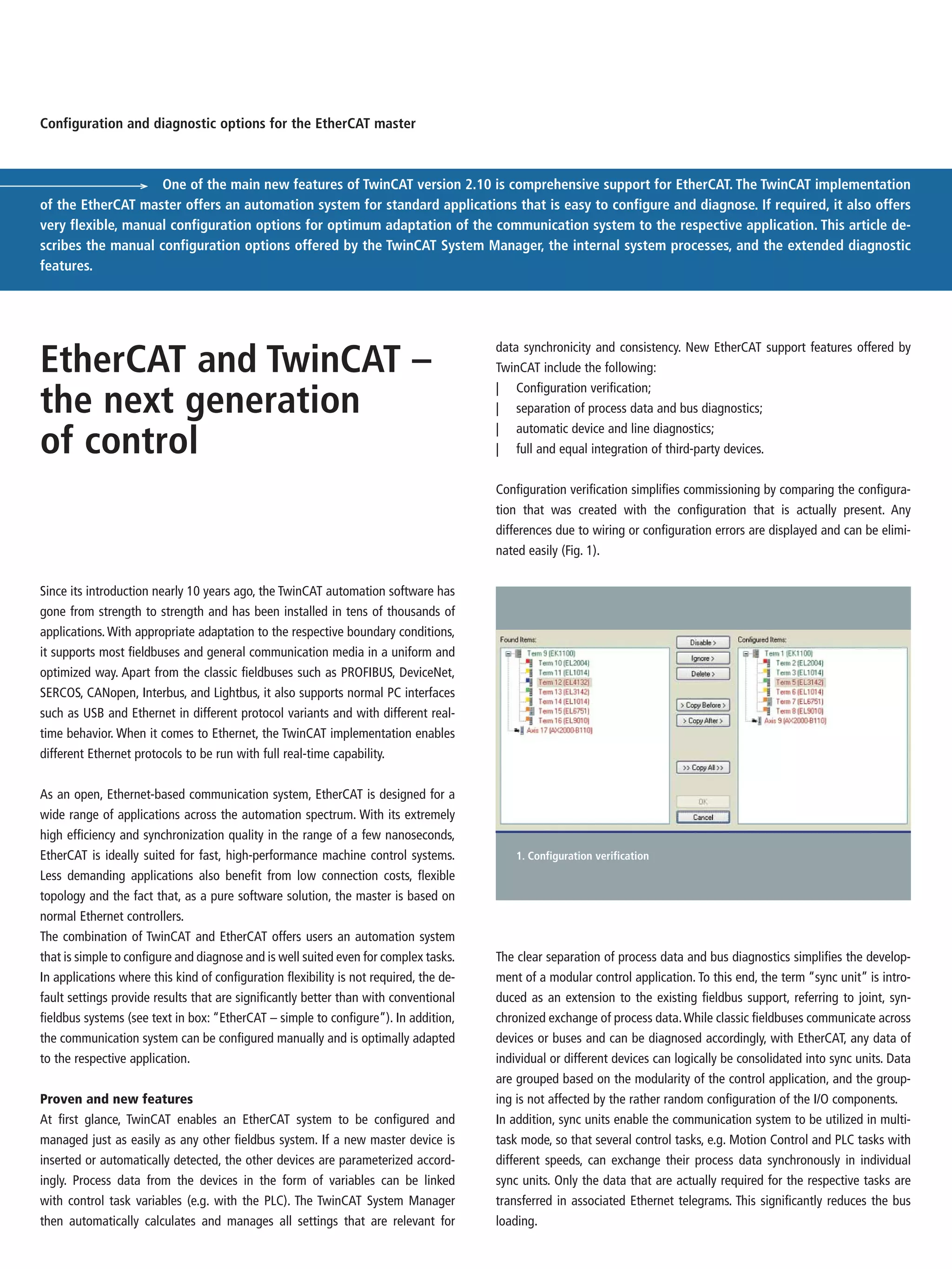
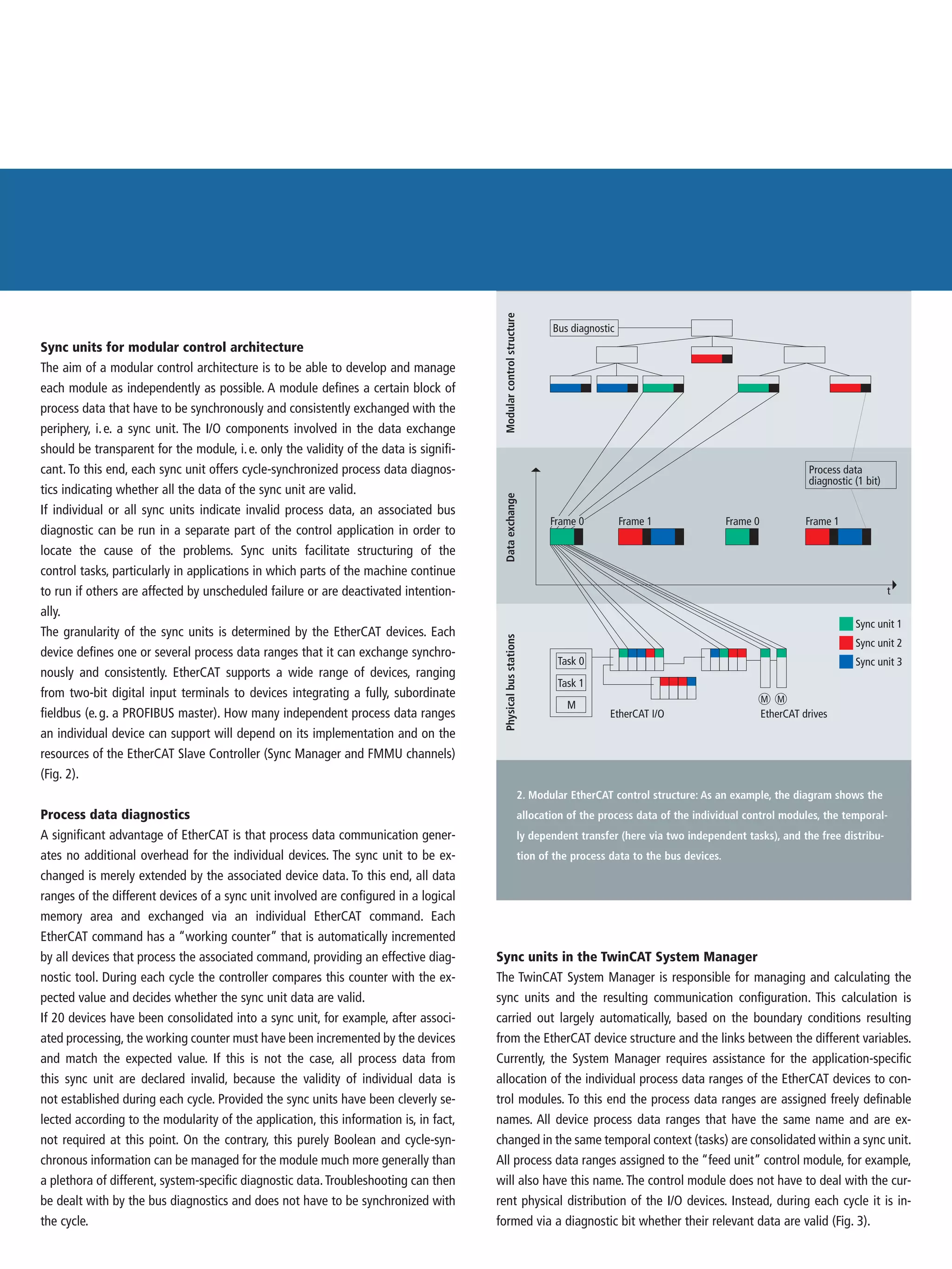
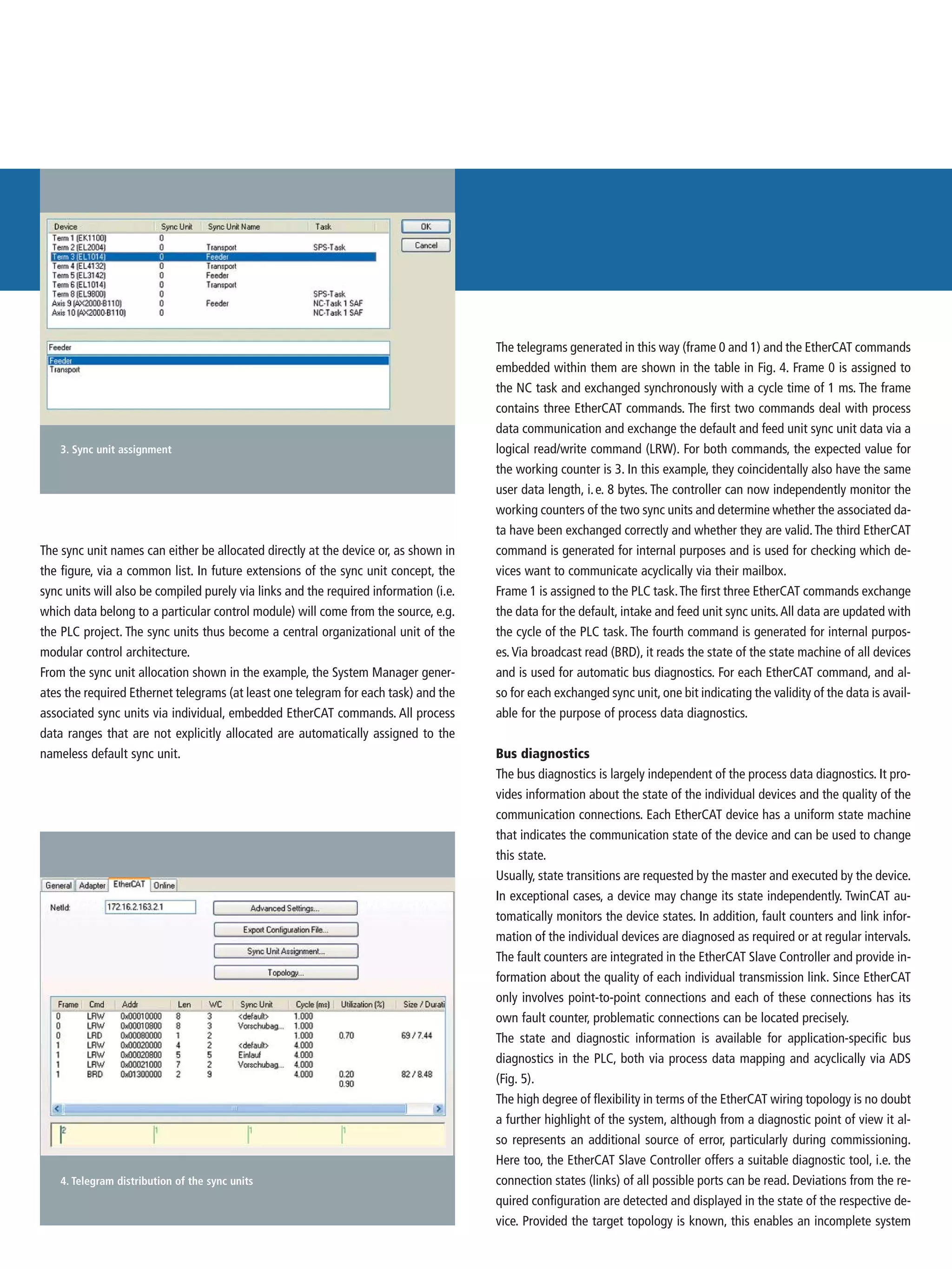
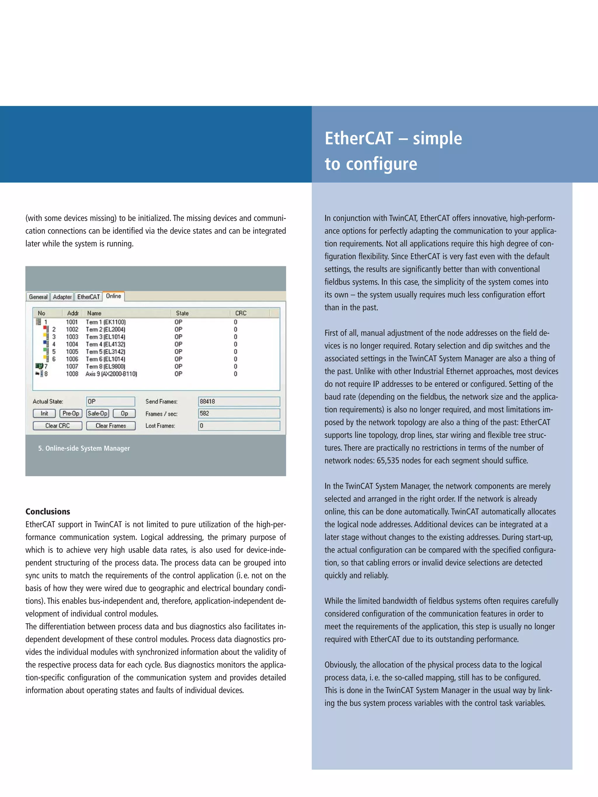
The document discusses TwinCAT automation software's support for EtherCAT communication. It describes how TwinCAT enables modular configuration of an EtherCAT system through sync units, which group process data independently of the physical device configuration. This allows application-independent development of individual control modules. The document also outlines TwinCAT's configuration and diagnostic capabilities for EtherCAT systems, such as configuration verification, separation of process and bus diagnostics, and automatic device diagnostics.
“eXtending” the Automation Toolbox: Introduction to TwinCAT 3 Software and eX...Design World
The document provides an overview of TwinCAT 3 software and eXtended Automation (XA) from Beckhoff Automation. It discusses (1) how TwinCAT 3 addresses customer wishes from TwinCAT 2 like integration, C/C++ support, and migration capabilities, (2) the key aspects of XA including engineering (XAE), architecture (XAA), and runtime (XAR) environments, and (3) new TwinCAT 3 capabilities such as support for multi-core systems, connectivity tools, and migration from TwinCAT 2 projects.
Implementation of T-Junction Traffic Light Control System Using Simatic S7-20...IJERA Editor
A conventional traffic light control system is designed by using devices such as timers, relays and
contactors etc. The critical timing operation is required to be carried out under the existence of heavy
traffic situations. This conventional practice leads to many problems that need additional maintenance
cost and subsequent delay for a long time. With the help of a PLC, the requirement of fast automation
and effective optimization of traffic light control system can be achieved. Use of PLC helps us to
develop this process not only for traffic signal on the roads, but also on the movement of trains and
the transfer of containers in ports in maritime works. In order to provide a solution to the above
problem, this paper introduces an execution and implementation of T-junction traffic control system
using SEIMENS S7-200 PLC. Programming in PLC is written in ladder logic with the help of STEP7
MICROWIN software
Development of Software for Estimation of Structural Dynamic Characteristics ...IRJET Journal
This document describes the development of software to estimate the structural dynamic characteristics of mechanical systems in real time. The software uses LabVIEW to analyze data from sensors measuring the response of a mechanical beam to applied forces. Signal processing methods extract parameters like resonance frequencies and damping from the sensor data. The software is also designed to provide closed-loop control to achieve a desired acceleration level at a specified point on the structure. This allows testing structural vibration within set parameters in the laboratory prior to flight.
Monitoring and Controlling Of Electric Overhead Travelling Crane Using PLC an...paperpublications3
Abstract: PLC and SCADA are the two new approaches used to control the motion of Electric Overhead travelling crane. Ladder logic diagram for EOT Cranes are designed for motion using variable frequency drives and contactor logic and performance of various parameters are analyzed and compared and image of E.O.T crane are designed in SCADA software and communication between PLC and Scada is done with the help of Siemens simulator .There is a provision of hydraulic motor for motion in main hoist if power failure of cranes takes place to avoid the unsafe condition and work under extreme condition.
This document describes an office security system that uses face recognition for access control. It involves the following:
1) Capturing images of visitors using a web camera and comparing the images to a database of authorized employees' faces using discrete cosine transform coefficients and Euclidean distance calculations to identify matches.
2) If a match is found, a signal is sent to open the door. Otherwise, the unknown image is transmitted over LAN to staff for identification and potential door opening.
3) An LPC1768 cortex microcontroller is used to control door access and transmit images over LAN due to its processing power and communication capabilities. The system provides contactless security access control for offices.
IJRET : International Journal of Research in Engineering and Technology is an international peer reviewed, online journal published by eSAT Publishing House for the enhancement of research in various disciplines of Engineering and Technology. The aim and scope of the journal is to provide an academic medium and an important reference for the advancement and dissemination of research results that support high-level learning, teaching and research in the fields of Engineering and Technology. We bring together Scientists, Academician, Field Engineers, Scholars and Students of related fields of Engineering and Technology
Microsoft Power Point Am Ptracs Presenatation Brief Pptus056444
AMPTRAC provides network intelligence through its hardware and software solutions. Its AMPTRAC hardware monitors network connectivity in real-time, while its iTRACS infrastructure management software provides automated work order processes, asset management, and detailed reports. This intelligence reduces downtime and increases productivity to ultimately help businesses increase profits.
1. The document discusses a distributed computer control system for industrial process control. It describes a system where remote stations are interconnected by a communications link and each remote station takes turns having supervisory control over the link according to a predetermined order.
2. It also discusses programmable logic controllers (PLCs) used in industrial control systems. PLCs generally have a central processing unit and input/output modules. Industry is moving toward more distributed control systems using smaller PLCs and network technologies.
3. The document covers data link communication in distributed control systems. It describes a system where each remote station sequentially assumes control of the communication link and aims to achieve high reliability information transfer between stations.
Scada protocols-and-communications-trendsSandip Roy
The document discusses SCADA protocols and communication trends. It describes how SCADA systems monitor and control processes across multiple locations using RTUs connected via local and wide area networks. Common protocols discussed include Modbus, ModbusX, DNP, ASCII, and IEEE 60870. The document also outlines legacy networks using low speeds of 300-1200 bps and how newer networks enable higher speeds of 9600 bps to meet increased data demands.
IMPLEMENTATION OF USER INTERFACE FOR MICROPROCESSOR TRAINER cscpconf
This paper aims to design and construct the microcontroller - based userinterface system and to
study input, computation and output for microprocessor trainer.The other two activities beyond
computation :input and output or I/O.This paper also aims to do high quality research in the
area of filesystems, as well as develop a good implementation on atleast one computersystem. A
computersystem's I/O performance must be commensurate (equal) with its CPU performance if
the I/O system is not to limit the system's total throughput.When hundreds to thousands of such
highperformance micro-processors are closely connected inscalablearray architecture, the
enormous CPU performance of the multi-computer requires an I/O system with correspondingly
high performance.A wellbalanced computer requires I/O performance commensurate with its
CPU performance. High performance computers, access large numbers of disks in parallel to
achieve the very appreciable I/O performance.
This PPT is based on the communication between a PLC and a SCADA system. The numerous communication protocols such as Modbus, Profibus, ControlNET, DeviceNET, HART, Ethernet, and Profinet are briefly explained in this ppt.
This document summarizes a paper presented at the 2nd IEEE International Conference on Power and Energy held in Johor Baharu, Malaysia from December 1-3, 2008. The paper discusses the development of a Supervisory Control and Data Acquisition (SCADA) based Remote Terminal Unit (RTU) for distribution automation systems. Specifically, it presents the system architecture, design requirements, RTU specifications, interface with the SCADA system, input/output modules, communication protocols, and results. The SCADA-based RTU was developed to provide fault isolation, monitoring, and control capabilities for low voltage distribution automation.
This document provides an overview of SCADA (Supervisory Control and Data Acquisition) systems. It discusses key components of SCADA including field instrumentation, remote stations, communication networks, and central monitoring stations. It also describes common SCADA configurations, modes of communication, and differences between SCADA and DCS systems. The goal is to introduce SCADA basics and provide context for those familiar and unfamiliar with these systems.
This document provides an overview of SCADA (Supervisory Control and Data Acquisition) systems. It describes the basic hardware and software architecture of SCADA, including distributed databases, data servers, PLCs, and control programs in the field. The document also outlines key SCADA functionality such as access control, HMI, trending, alarm handling, logging, archiving, report generation, and automation capabilities. SCADA systems are typically used in industrial processes and facilities to monitor and control equipment and processes.
This document discusses approaches and best practices for substation integration and automation. It provides an overview of system architecture, communication protocols, and a utility case study. The key points are:
- There are different levels of integration, from individual IED implementation to full substation automation and connection to the utility enterprise.
- Protocols like DNP3 and IEC 61850 are important for allowing devices from different vendors to communicate. Care must be taken that devices support the same protocols and versions.
- A case study of Omaha Public Power District's project demonstrates integrating IEDs using the IEC 61850 protocol over Ethernet networks for two substations and a training simulator.
Programmable logic controllers (PLCs) are digital electronic devices that use a programmable memory to store instructions and implement functions like logic, sequencing, timing, and arithmetic to control machines and processes. PLCs were developed to simplify control automation by replacing relay logic systems. A PLC consists of a processor, memory, input/output modules, and a power supply. It reads input signals, executes a stored program to control outputs, and then repeats in a scan cycle. Common programming methods for PLCs include ladder logic, statement list, and function block diagrams. PLCs are widely used in industry for their flexibility, reliability, and ability to operate in harsh environments.
Implementation of METRO rail using PLC and SCADAmanogna gwen
This document discusses the implementation of a metro rail system using programmable logic controllers (PLCs) and supervisory control and data acquisition (SCADA). It describes how PLCs are used for automation and control functions, while SCADA is used for high-level supervision, data collection, and presentation. The document outlines the components, functions, and block diagram of a metro rail system that uses PLCs to interface with sensors and machinery, while SCADA is used for monitoring train locations to help avoid accidents and collisions.
This document proposes a reconfigurable sensor data acquisition system based on FPGA for industrial computerization and control. The system uses FPGA reconfiguration technology to allow dynamic switching of sensor protocols and functions without powering off. It achieves static reconfiguration through an FPGA-controlled switch matrix and dynamic reconfiguration by storing configuration files on an FPGA configuration flash card. This provides flexibility to change sensor connections and logic online for improved real-time performance, universality, and continuous operation.
Programmable Logic Controllers Paper (PLC) SM54Subhash Mahla
This document discusses programmable logic controllers (PLCs). It begins by defining a PLC as a digitally operating electronic apparatus that uses programmable memory to implement logic, sequencing, timing and other functions to control machines and processes. The document then describes the basic components of a PLC, including I/O modules, a processor, power supply, memory unit and network interface. It explains how PLCs are programmed using programming units connected to computers and the transfer of programs to PLC memory using EEPROM chips.
The document discusses the evolution of process control systems from early pneumatic and analog electronic implementations to modern digital implementations using distributed control systems (DCS). It describes the key components and advantages of DCS, including flexibility, reliability, and the ability to implement advanced digital control strategies. DCS networks allow different control modes and distributed control for large, complex processes.
FPGA Data Acquisition System in Industrial SceneNishmi Suresh
This document discusses a reconfigurable sensor data acquisition system based on FPGA for industrial computerization and control. It addresses problems with traditional data acquisition systems like lack of universality, continuity of working, and real-time performance. The proposed system uses an FPGA for dynamic and static reconfiguration to allow changing sensor protocols and functions without powering off. It implements static reconfiguration using a switch matrix and dynamic reconfiguration using SystemACE CF technology to reconfigure parts of the FPGA logic in real-time. This provides benefits like reduced cost, power consumption, and increased system flexibility.
This document discusses supervisory control and data acquisition (SCADA) systems. It describes the typical hardware and software architectures of SCADA, including distributed databases, data servers, programmable logic controllers, and field buses. The document outlines common SCADA functions such as access control, human-machine interface, trending, alarm handling, logging, archiving, report generation, and automation. It also mentions SCADA development tools and data access mechanisms. In conclusion, the document states that SCADA systems offer more front-end functionality, efficient storage, and device-oriented configuration than distributed control systems.
Practical DNP3, 60870.5 & Modern SCADA Communication SystemsLiving Online
This document introduces topics related to SCADA systems and communication standards that will be covered in more detail later. It provides a high-level overview of SCADA systems, describing how they collect data from remote sites and transmit it to a central location for monitoring and control. It also briefly outlines the OSI 7-layer model and its role in defining communication standards between open systems to ensure interoperability.
Practical Distribution & Substation Automation (Incl. Communications) for Ele...Living Online
This document provides an introduction to power system automation. It defines power system automation as a system for managing, controlling, and protecting an electrical power system using real-time information, control applications, and electrical protection. The core components of power system automation are described as local intelligence, data communications, supervisory control and monitoring. The document outlines the basic architecture of power system automation which includes the object division comprising intelligent electronic devices and remote terminal units, the communications network, and the SCADA master station which receives data and issues commands.
Dhiraj seminar # power system automationvision2d16
This document discusses power system automation and SCADA (Supervisory Control and Data Acquisition) systems. It describes the key components of SCADA including instrument transformers, transducers, relays, RTUs, meters, digital fault recorders, PLCs and HMIs. The advantages of power system automation are that it makes the system more efficient with less manpower and is flexible, simple and reliable. Some applications discussed are smart grids, smart meters and automatic generation control.
IRJET-Design of ARM Based Data Acquisition and Control System for Engine Asse...IRJET Journal
This document describes the design of an ARM-based data acquisition and control system for monitoring engine assembly. The system uses an ARM7 microcontroller to acquire data from assembly tools like a DC nutrunner via Ethernet. It then analyzes the torque values to determine if the assembly process parameters are within acceptable limits and provide output as OK or NOK. The system offers networked control and data acquisition through an industrial Ethernet network using TCP/IP protocol. This provides a low-cost and flexible alternative to traditional distributed control systems for engine assembly quality monitoring and control.
1. The document discusses a distributed computer control system for industrial processes. In the system, remote stations take turns having supervisory control over a communications link in a predetermined sequence. When a remote station's turn is over, it transmits a message and the next station takes control.
2. The system uses programmable logic controllers (PLCs) connected over a network to control industrial devices in a distributed, decentralized manner. This offers more flexibility and scalability than a centralized system. Small, intelligent PLCs gather local data and share it across the network.
3. The invention relates to industrial control systems with multiple remotely located process control units connected by a communications link. Each remote unit sequentially takes supervisory
Development of of power plants functionality Hossam Zein
This document discusses implementing an electrical network monitoring and control system. It examines challenges with using serial communication links for control and proposes adopting Ethernet as the physical and data link layer protocol. Specifically, it recommends replacing gateway-based architectures with a client-server model to allow multiple systems like DCS and ENMCS to independently communicate with devices like motor protection relays over high-bandwidth Ethernet. This achieves flexible communications, easy engineering access, and responses fast enough for motor control.
The Design of Multi-Platforms Rail Intelligence Flatness Detection SystemIJRESJOURNAL
ABSTRACT: In this paper,we design a Multi-platforms intelligent system for flatness detection of rail welding headbased on thedevelopment environment of Android software .The system uses a STM32 chip as control core, a handheld smart terminal or personal computer as the carrier. The datas transmitted to intelligent terminal or computer through the bluetooth communication technology are processed rapidly, the data curve is drawed and the flatness characteristic parameters of the measured rail welding head is identified. The system provides a friendly intuitive monitoring and operation interface, has the characteristics of fast, reliable, energy saving, high accuracy, etc.
This document provides an overview of power system automation and data acquisition systems. It discusses:
1) The role of data acquisition systems in power system automation and how they collect data from the power network using sensors and send it to programmable logic controllers and computers.
2) The key components of power system automation including electrical protection, control, measurement, monitoring, and data communication.
3) The architecture of power system automation including three levels - field equipment, protection/control equipment, and operator displays - connected by communication networks.
This document discusses using the VT System for automated testing of an electronic control unit (ECU) in a vehicle. It describes how the VT System can simulate loads and sensors to test the ECU without needing the actual vehicle components. The VT System modules connect to the ECU inputs and outputs to drive and monitor them. The ECU also connects to the CANoe software via a CAN interface to simulate communications with other ECUs. Test cases are created in VTestStudio and can execute automatically to test the ECU functionality. This allows testing the ECU in early development phases in a controlled and repeatable way.
Model Based Hierarchical and Distributed Control of Discrete Event Robotic Sy...Waqas Tariq
This paper deals with the modeling and control of discrete event robotic systems using extended Petri nets, and proposes a methodology of model based design and implementation of hierarchical and distributed control. Based on the hierarchical approach, the Petri net is translated into the detailed Petri net by stepwise refinements from the highest conceptual level to the lowest machine control level. The coordinator is introduced to coordinate the distributed controllers so that the decomposed transitions fire at the same time. System coordination algorithm through communication between the coordinator and the controllers, is implemented using multithread programming. By the proposed method, modeling, simulation and control of large and complex robotic systems can be performed consistently using Petri nets.
Software-Defined Networking Changes for the Paradigm for Mission-Critical Ope...Wheeler Flemming
SDN offers advantages over traditional Ethernet for OT networks by providing microsecond failover times, predictable network behavior through application-specific traffic engineering, stronger security through a deny-by-default approach, and simplified network design, testing and monitoring through centralized control and configuration of network switches. SDN resolves limitations of traditional Ethernet including slow healing times, forced behavior, lack of security, difficult testing and lack of network visibility in OT networks managing critical infrastructure systems.
The primary goal of the ISOBUS software stack is to standardize communication between the tractor Control Unit (tractor ECU) , the implement control unit (automotive Electronic Control Unit), Virtual Terminal and Web-based or Mobile Application.
ISOBUS stack is a software protocol complaint to ISO 11783 standard.
https://www.embitel.com/blog/embedded-blog/what-is-isobus-learn-about-its-architecture-and-diagnostic-applications
Multi-axis position control by EtherCAT real-time networking:
The strength of EtherCAT synchronization techniques allows it to be compatible with both low and high demanding applications. Combined with the correct implementation of both the network protocol, and a proper device profile, a true distributed motion control can be achieved.
Automation and Robotics 20ME51I Week 3 Theory Notes.pdfGandhibabu8
PLC systems use point-to-point and network communication links to exchange data. Point-to-point links use serial communication between two devices, while network links connect multiple devices over a local area network (LAN). Common serial communication standards are RS-232, RS-485, and protocols like UART, SPI, and I2C. Parallel communication transfers multiple bits simultaneously but is generally slower than serial. The OSI model defines seven layers for network communication, including the physical, data link, network, and transport layers. TCP/IP is a common networking protocol that uses IP for routing and TCP for reliable data transmission. Networking devices like routers, switches, and gateways connect PLCs and allow communication over different network
This document discusses load balancing in 5G networks through offloading traffic between LTE and Wi-Fi networks. It describes the COHERENT architectural framework, which uses network graphs and two main control components - the Central Controller and Coordinator (C3) and Real-Time Controller (RTC) - to manage resource allocation and control tasks like traffic steering and load balancing across heterogeneous networks. Specifically, it focuses on a load balancing use case where traffic is offloaded from overloaded LTE networks to Wi-Fi networks to improve resource utilization and system performance.
This document provides an overview of advanced vehicle control systems and automotive electronics. It begins with an outline of topics to be covered, including vehicle communication, network topology, automotive networks, bus systems, vehicle system architecture, and more. It then defines automotronics and discusses how modern vehicles rely on electronics and computer systems for functions like engine control, transmission control, stability control systems and more. The document discusses network topologies used in vehicles like bus, star and ring networks. It covers different automotive network standards and bus systems like CAN, LIN, FlexRay and MOST. Finally, it discusses requirements for automotive bus systems like data transfer rates, interference immunity and real-time capability.
Scada Based Online Circuit Breaker Monitoring SystemIOSR Journals
This document discusses the design and implementation of an online monitoring system for circuit breakers using SCADA technology. The system would monitor key parameters of circuit breakers like currents, voltages, pressures and temperatures. Sensors would collect data which would be sent to a data acquisition unit and then to a central computer via a communication network. The computer would store data histories and use SCADA software to allow remote monitoring. The system architecture includes sensors, intelligent electronic devices for data collection, and a central computer running analysis software to evaluate breaker condition and guide maintenance. The online monitoring allows reliable supervision of circuit breakers to improve power system reliability.
A novel Ethernet based processing system for remote source harmonic detectionTELKOMNIKA JOURNAL
This work is carried out to objectively establish a new method to detect harmonics and measure the total harmonic distortion (THD) in a remote source, such as a high voltage transformer. The proposed approach utilized embedded design techniques to construct an embedded processor system with Ethernet intellectual property core to acquire data from a remote harmonics source. The designed system has several notable merits, namely, it is portable that can be applied in the work field, and it avoids workers from being subject to a hazard high voltage shock as well as its simplicity and high accuracy. The harmonics detection and analysis are achieved by inserting a microcontroller system near the high voltage transformer to acquire the necessary data and transmit it to a remote embedded processor system that is used to detect and analyze the harmonics. The microcontroller and the processor systems are connected by a wide-area network (WAN) through Ethernet and transmission control protocol/internet protocol (TCP/IP) protocols. The processor system is accommodated to perform 128 points fast Fourier transform for harmonics detection. Matlab simulations are used to validate the results. It is found that the results match very accurately the simulation results with an error of less than 0.02%.
Test platform for electronic control units of high-performance safety-critica...IJECEIAES
In this paper we are mostly concerned with the problem of testing electronic control units of synchronized electric power actuators. This task is particularly complex for safety critical applications, where it is crucial that the control system properly reacts in response to the faults that are hard to reproduce and verify. A cost-effective flexible and reconfigurable test platform is proposed, discussing its architecture and implementation. The proposed system facilitates the phase of definition and development of the electronic control unit, allowing the interfacing towards both hydraulic and electromechanical actuators, and having a high flexibility as regards the I/O signals. Some results, obtained during the laboratory test activity, are also presented.
Services interfaces for interoperability of signaling computerinterlocking on...IJECEIAES
Technological developments in the field of railway signaling have allowed more and more flexibility in the management of rail traffic, especially with computer interlocking. However, differences in signaling principles from one country to another as well as differences in the structure of interlocking software and communication protocols depending on suppliers lead to interoperability difficulties at the borders between computer interlocking. Some deployed projects deal with interoperability issues regarding the communication of signaling information between the train and interlocking like the European rail traffic management system (ERTMS) project. Unfortunately, the interoperability between interlocking themselves is still not achieved. Some deployed projects deal with interoperability issues regarding the communication of signaling information between the train and interlocking like the ERTMS project. Unfortunately, the interoperability between interlocking themselves is still not achieved. This article draws up a proposed model for interfacing at the interlocking boundaries based on service-oriented architecture (SOA). In addition, to ensure the coupling of SOA services to the internal functions of the signaling computer interlocking, a distributed architecture of programmable logic controller according to the IEC 61499 standard is suggested.
This document provides an overview of SCADA (Supervisory Control And Data Acquisition) systems. It defines key SCADA concepts like telemetry, data acquisition, and the differences between SCADA and DCS systems. The document also describes the typical components of a SCADA system, including field instrumentation, remote stations, communication networks, and central monitoring stations. It provides examples of common SCADA system configurations and communication modes.
The document provides an introduction to SCADA (Supervisory Control And Data Acquisition) systems. It defines key terms like telemetry, data acquisition, and the differences between SCADA and DCS. The document also describes the typical components of a SCADA system, including field instrumentation, remote stations, communication networks, and central monitoring systems. It provides examples of components and discusses how they work together in a SCADA system.
The T2750 PAC hardware provides high-performance control with cost-effective redundancy options in a versatile modular system. Powerful instruments, the control units, and the I/O system form the basis of a complete distributed control and recording environment. This environment is capable of continuous analog, logic, sequential control, batch management, secure data recording at point of measurement, and setpoint programming.
Electric vehicle and photovoltaic advanced roles in enhancing the financial p...IJECEIAES
Climate change's impact on the planet forced the United Nations and governments to promote green energies and electric transportation. The deployments of photovoltaic (PV) and electric vehicle (EV) systems gained stronger momentum due to their numerous advantages over fossil fuel types. The advantages go beyond sustainability to reach financial support and stability. The work in this paper introduces the hybrid system between PV and EV to support industrial and commercial plants. This paper covers the theoretical framework of the proposed hybrid system including the required equation to complete the cost analysis when PV and EV are present. In addition, the proposed design diagram which sets the priorities and requirements of the system is presented. The proposed approach allows setup to advance their power stability, especially during power outages. The presented information supports researchers and plant owners to complete the necessary analysis while promoting the deployment of clean energy. The result of a case study that represents a dairy milk farmer supports the theoretical works and highlights its advanced benefits to existing plants. The short return on investment of the proposed approach supports the paper's novelty approach for the sustainable electrical system. In addition, the proposed system allows for an isolated power setup without the need for a transmission line which enhances the safety of the electrical network
Introduction- e - waste – definition - sources of e-waste– hazardous substances in e-waste - effects of e-waste on environment and human health- need for e-waste management– e-waste handling rules - waste minimization techniques for managing e-waste – recycling of e-waste - disposal treatment methods of e- waste – mechanism of extraction of precious metal from leaching solution-global Scenario of E-waste – E-waste in India- case studies.
Advanced control scheme of doubly fed induction generator for wind turbine us...IJECEIAES
This paper describes a speed control device for generating electrical energy on an electricity network based on the doubly fed induction generator (DFIG) used for wind power conversion systems. At first, a double-fed induction generator model was constructed. A control law is formulated to govern the flow of energy between the stator of a DFIG and the energy network using three types of controllers: proportional integral (PI), sliding mode controller (SMC) and second order sliding mode controller (SOSMC). Their different results in terms of power reference tracking, reaction to unexpected speed fluctuations, sensitivity to perturbations, and resilience against machine parameter alterations are compared. MATLAB/Simulink was used to conduct the simulations for the preceding study. Multiple simulations have shown very satisfying results, and the investigations demonstrate the efficacy and power-enhancing capabilities of the suggested control system.
Use PyCharm for remote debugging of WSL on a Windo cf5c162d672e4e58b4dde5d797...shadow0702a
This document serves as a comprehensive step-by-step guide on how to effectively use PyCharm for remote debugging of the Windows Subsystem for Linux (WSL) on a local Windows machine. It meticulously outlines several critical steps in the process, starting with the crucial task of enabling permissions, followed by the installation and configuration of WSL.
The guide then proceeds to explain how to set up the SSH service within the WSL environment, an integral part of the process. Alongside this, it also provides detailed instructions on how to modify the inbound rules of the Windows firewall to facilitate the process, ensuring that there are no connectivity issues that could potentially hinder the debugging process.
The document further emphasizes on the importance of checking the connection between the Windows and WSL environments, providing instructions on how to ensure that the connection is optimal and ready for remote debugging.
It also offers an in-depth guide on how to configure the WSL interpreter and files within the PyCharm environment. This is essential for ensuring that the debugging process is set up correctly and that the program can be run effectively within the WSL terminal.
Additionally, the document provides guidance on how to set up breakpoints for debugging, a fundamental aspect of the debugging process which allows the developer to stop the execution of their code at certain points and inspect their program at those stages.
Finally, the document concludes by providing a link to a reference blog. This blog offers additional information and guidance on configuring the remote Python interpreter in PyCharm, providing the reader with a well-rounded understanding of the process.
Comparative analysis between traditional aquaponics and reconstructed aquapon...bijceesjournal
The aquaponic system of planting is a method that does not require soil usage. It is a method that only needs water, fish, lava rocks (a substitute for soil), and plants. Aquaponic systems are sustainable and environmentally friendly. Its use not only helps to plant in small spaces but also helps reduce artificial chemical use and minimizes excess water use, as aquaponics consumes 90% less water than soil-based gardening. The study applied a descriptive and experimental design to assess and compare conventional and reconstructed aquaponic methods for reproducing tomatoes. The researchers created an observation checklist to determine the significant factors of the study. The study aims to determine the significant difference between traditional aquaponics and reconstructed aquaponics systems propagating tomatoes in terms of height, weight, girth, and number of fruits. The reconstructed aquaponics system’s higher growth yield results in a much more nourished crop than the traditional aquaponics system. It is superior in its number of fruits, height, weight, and girth measurement. Moreover, the reconstructed aquaponics system is proven to eliminate all the hindrances present in the traditional aquaponics system, which are overcrowding of fish, algae growth, pest problems, contaminated water, and dead fish.
Discover the latest insights on Data Driven Maintenance with our comprehensive webinar presentation. Learn about traditional maintenance challenges, the right approach to utilizing data, and the benefits of adopting a Data Driven Maintenance strategy. Explore real-world examples, industry best practices, and innovative solutions like FMECA and the D3M model. This presentation, led by expert Jules Oudmans, is essential for asset owners looking to optimize their maintenance processes and leverage digital technologies for improved efficiency and performance. Download now to stay ahead in the evolving maintenance landscape.
Redefining brain tumor segmentation: a cutting-edge convolutional neural netw...IJECEIAES
Medical image analysis has witnessed significant advancements with deep learning techniques. In the domain of brain tumor segmentation, the ability to
precisely delineate tumor boundaries from magnetic resonance imaging (MRI)
scans holds profound implications for diagnosis. This study presents an ensemble convolutional neural network (CNN) with transfer learning, integrating
the state-of-the-art Deeplabv3+ architecture with the ResNet18 backbone. The
model is rigorously trained and evaluated, exhibiting remarkable performance
metrics, including an impressive global accuracy of 99.286%, a high-class accuracy of 82.191%, a mean intersection over union (IoU) of 79.900%, a weighted
IoU of 98.620%, and a Boundary F1 (BF) score of 83.303%. Notably, a detailed comparative analysis with existing methods showcases the superiority of
our proposed model. These findings underscore the model’s competence in precise brain tumor localization, underscoring its potential to revolutionize medical
image analysis and enhance healthcare outcomes. This research paves the way
for future exploration and optimization of advanced CNN models in medical
imaging, emphasizing addressing false positives and resource efficiency.
Null Bangalore | Pentesters Approach to AWS IAMDivyanshu
#Abstract:
- Learn more about the real-world methods for auditing AWS IAM (Identity and Access Management) as a pentester. So let us proceed with a brief discussion of IAM as well as some typical misconfigurations and their potential exploits in order to reinforce the understanding of IAM security best practices.
- Gain actionable insights into AWS IAM policies and roles, using hands on approach.
#Prerequisites:
- Basic understanding of AWS services and architecture
- Familiarity with cloud security concepts
- Experience using the AWS Management Console or AWS CLI.
- For hands on lab create account on [killercoda.com](https://killercoda.com/cloudsecurity-scenario/)
# Scenario Covered:
- Basics of IAM in AWS
- Implementing IAM Policies with Least Privilege to Manage S3 Bucket
- Objective: Create an S3 bucket with least privilege IAM policy and validate access.
- Steps:
- Create S3 bucket.
- Attach least privilege policy to IAM user.
- Validate access.
- Exploiting IAM PassRole Misconfiguration
-Allows a user to pass a specific IAM role to an AWS service (ec2), typically used for service access delegation. Then exploit PassRole Misconfiguration granting unauthorized access to sensitive resources.
- Objective: Demonstrate how a PassRole misconfiguration can grant unauthorized access.
- Steps:
- Allow user to pass IAM role to EC2.
- Exploit misconfiguration for unauthorized access.
- Access sensitive resources.
- Exploiting IAM AssumeRole Misconfiguration with Overly Permissive Role
- An overly permissive IAM role configuration can lead to privilege escalation by creating a role with administrative privileges and allow a user to assume this role.
- Objective: Show how overly permissive IAM roles can lead to privilege escalation.
- Steps:
- Create role with administrative privileges.
- Allow user to assume the role.
- Perform administrative actions.
- Differentiation between PassRole vs AssumeRole
Try at [killercoda.com](https://killercoda.com/cloudsecurity-scenario/)
Software Engineering and Project Management - Introduction, Modeling Concepts...Prakhyath Rai
Introduction, Modeling Concepts and Class Modeling: What is Object orientation? What is OO development? OO Themes; Evidence for usefulness of OO development; OO modeling history. Modeling
as Design technique: Modeling, abstraction, The Three models. Class Modeling: Object and Class Concept, Link and associations concepts, Generalization and Inheritance, A sample class model, Navigation of class models, and UML diagrams
Building the Analysis Models: Requirement Analysis, Analysis Model Approaches, Data modeling Concepts, Object Oriented Analysis, Scenario-Based Modeling, Flow-Oriented Modeling, class Based Modeling, Creating a Behavioral Model.
cnn.pptx Convolutional neural network used for image classication
Ethercat twincat e
1. Since its introduction nearly 10 years ago, the TwinCAT automation software has
gone from strength to strength and has been installed in tens of thousands of
applications. With appropriate adaptation to the respective boundary conditions,
it supports most fieldbuses and general communication media in a uniform and
optimized way. Apart from the classic fieldbuses such as PROFIBUS, DeviceNet,
SERCOS, CANopen, Interbus, and Lightbus, it also supports normal PC interfaces
such as USB and Ethernet in different protocol variants and with different real-
time behavior. When it comes to Ethernet, the TwinCAT implementation enables
different Ethernet protocols to be run with full real-time capability.
As an open, Ethernet-based communication system, EtherCAT is designed for a
wide range of applications across the automation spectrum. With its extremely
high efficiency and synchronization quality in the range of a few nanoseconds,
EtherCAT is ideally suited for fast, high-performance machine control systems.
Less demanding applications also benefit from low connection costs, flexible
topology and the fact that, as a pure software solution, the master is based on
normal Ethernet controllers.
The combination of TwinCAT and EtherCAT offers users an automation system
that is simple to configure and diagnose and is well suited even for complex tasks.
In applications where this kind of configuration flexibility is not required, the de-
fault settings provide results that are significantly better than with conventional
fieldbus systems (see text in box: “EtherCAT – simple to configure”). In addition,
the communication system can be configured manually and is optimally adapted
to the respective application.
Proven and new features
At first glance, TwinCAT enables an EtherCAT system to be configured and
managed just as easily as any other fieldbus system. If a new master device is
inserted or automatically detected, the other devices are parameterized accord-
ingly. Process data from the devices in the form of variables can be linked
with control task variables (e.g. with the PLC). The TwinCAT System Manager
then automatically calculates and manages all settings that are relevant for
data synchronicity and consistency. New EtherCAT support features offered by
TwinCAT include the following:
| Configuration verification;
| separation of process data and bus diagnostics;
| automatic device and line diagnostics;
| full and equal integration of third-party devices.
Configuration verification simplifies commissioning by comparing the configura-
tion that was created with the configuration that is actually present. Any
differences due to wiring or configuration errors are displayed and can be elimi-
nated easily (Fig. 1).
One of the main new features of TwinCAT version 2.10 is comprehensive support for EtherCAT. The TwinCAT implementation
of the EtherCAT master offers an automation system for standard applications that is easy to configure and diagnose. If required, it also offers
very flexible, manual configuration options for optimum adaptation of the communication system to the respective application. This article de-
scribes the manual configuration options offered by the TwinCAT System Manager, the internal system processes, and the extended diagnostic
features.
Configuration and diagnostic options for the EtherCAT master
EtherCAT and TwinCAT –
the next generation
of control
1. Configuration verification
The clear separation of process data and bus diagnostics simplifies the develop-
ment of a modular control application. To this end, the term “sync unit” is intro-
duced as an extension to the existing fieldbus support, referring to joint, syn-
chronized exchange of process data.While classic fieldbuses communicate across
devices or buses and can be diagnosed accordingly, with EtherCAT, any data of
individual or different devices can logically be consolidated into sync units. Data
are grouped based on the modularity of the control application, and the group-
ing is not affected by the rather random configuration of the I/O components.
In addition, sync units enable the communication system to be utilized in multi-
task mode, so that several control tasks, e.g. Motion Control and PLC tasks with
different speeds, can exchange their process data synchronously in individual
sync units. Only the data that are actually required for the respective tasks are
transferred in associated Ethernet telegrams. This significantly reduces the bus
loading.
2. Modularcontrolstructure
Sync unit 3
Sync unit 2
Sync unit 1
DataexchangePhysicalbusstations
Bus diagnostic
Process data
diagnostic (1 bit)
Frame 1 Frame 0 Frame 1
t
EtherCAT I/O EtherCAT drives
M M
Task 0
Task 1
M
Frame 0
Sync units for modular control architecture
The aim of a modular control architecture is to be able to develop and manage
each module as independently as possible. A module defines a certain block of
process data that have to be synchronously and consistently exchanged with the
periphery, i.e. a sync unit. The I/O components involved in the data exchange
should be transparent for the module, i.e. only the validity of the data is signifi-
cant. To this end, each sync unit offers cycle-synchronized process data diagnos-
tics indicating whether all the data of the sync unit are valid.
If individual or all sync units indicate invalid process data, an associated bus
diagnostic can be run in a separate part of the control application in order to
locate the cause of the problems. Sync units facilitate structuring of the
control tasks, particularly in applications in which parts of the machine continue
to run if others are affected by unscheduled failure or are deactivated intention-
ally.
The granularity of the sync units is determined by the EtherCAT devices. Each
device defines one or several process data ranges that it can exchange synchro-
nously and consistently. EtherCAT supports a wide range of devices, ranging
from two-bit digital input terminals to devices integrating a fully, subordinate
fieldbus (e.g. a PROFIBUS master). How many independent process data ranges
an individual device can support will depend on its implementation and on the
resources of the EtherCAT Slave Controller (Sync Manager and FMMU channels)
(Fig. 2).
Process data diagnostics
A significant advantage of EtherCAT is that process data communication gener-
ates no additional overhead for the individual devices. The sync unit to be ex-
changed is merely extended by the associated device data. To this end, all data
ranges of the different devices of a sync unit involved are configured in a logical
memory area and exchanged via an individual EtherCAT command. Each
EtherCAT command has a “working counter” that is automatically incremented
by all devices that process the associated command, providing an effective diag-
nostic tool. During each cycle the controller compares this counter with the ex-
pected value and decides whether the sync unit data are valid.
If 20 devices have been consolidated into a sync unit, for example, after associ-
ated processing, the working counter must have been incremented by the devices
and match the expected value. If this is not the case, all process data from
this sync unit are declared invalid, because the validity of individual data is
not established during each cycle. Provided the sync units have been cleverly se-
lected according to the modularity of the application, this information is, in fact,
not required at this point. On the contrary, this purely Boolean and cycle-syn-
chronous information can be managed for the module much more generally than
a plethora of different, system-specific diagnostic data.Troubleshooting can then
be dealt with by the bus diagnostics and does not have to be synchronized with
the cycle.
Sync units in the TwinCAT System Manager
The TwinCAT System Manager is responsible for managing and calculating the
sync units and the resulting communication configuration. This calculation is
carried out largely automatically, based on the boundary conditions resulting
from the EtherCAT device structure and the links between the different variables.
Currently, the System Manager requires assistance for the application-specific
allocation of the individual process data ranges of the EtherCAT devices to con-
trol modules. To this end the process data ranges are assigned freely definable
names. All device process data ranges that have the same name and are ex-
changed in the same temporal context (tasks) are consolidated within a sync unit.
All process data ranges assigned to the “feed unit” control module, for example,
will also have this name. The control module does not have to deal with the cur-
rent physical distribution of the I/O devices. Instead, during each cycle it is in-
formed via a diagnostic bit whether their relevant data are valid (Fig. 3).
2. Modular EtherCAT control structure: As an example, the diagram shows the
allocation of the process data of the individual control modules, the temporal-
ly dependent transfer (here via two independent tasks), and the free distribu-
tion of the process data to the bus devices.
3. The sync unit names can either be allocated directly at the device or, as shown in
the figure, via a common list. In future extensions of the sync unit concept, the
sync units will also be compiled purely via links and the required information (i.e.
which data belong to a particular control module) will come from the source, e.g.
the PLC project. The sync units thus become a central organizational unit of the
modular control architecture.
From the sync unit allocation shown in the example, the System Manager gener-
ates the required Ethernet telegrams (at least one telegram for each task) and the
associated sync units via individual, embedded EtherCAT commands. All process
data ranges that are not explicitly allocated are automatically assigned to the
nameless default sync unit.
The telegrams generated in this way (frame 0 and 1) and the EtherCAT commands
embedded within them are shown in the table in Fig. 4. Frame 0 is assigned to
the NC task and exchanged synchronously with a cycle time of 1 ms. The frame
contains three EtherCAT commands. The first two commands deal with process
data communication and exchange the default and feed unit sync unit data via a
logical read/write command (LRW). For both commands, the expected value for
the working counter is 3. In this example, they coincidentally also have the same
user data length, i.e. 8 bytes. The controller can now independently monitor the
working counters of the two sync units and determine whether the associated da-
ta have been exchanged correctly and whether they are valid.The third EtherCAT
command is generated for internal purposes and is used for checking which de-
vices want to communicate acyclically via their mailbox.
Frame 1 is assigned to the PLC task.The first three EtherCAT commands exchange
the data for the default, intake and feed unit sync units.All data are updated with
the cycle of the PLC task. The fourth command is generated for internal purpos-
es.Via broadcast read (BRD), it reads the state of the state machine of all devices
and is used for automatic bus diagnostics. For each EtherCAT command, and al-
so for each exchanged sync unit, one bit indicating the validity of the data is avail-
able for the purpose of process data diagnostics.
Bus diagnostics
The bus diagnostics is largely independent of the process data diagnostics. It pro-
vides information about the state of the individual devices and the quality of the
communication connections. Each EtherCAT device has a uniform state machine
that indicates the communication state of the device and can be used to change
this state.
Usually, state transitions are requested by the master and executed by the device.
In exceptional cases, a device may change its state independently. TwinCAT au-
tomatically monitors the device states. In addition, fault counters and link infor-
mation of the individual devices are diagnosed as required or at regular intervals.
The fault counters are integrated in the EtherCAT Slave Controller and provide in-
formation about the quality of each individual transmission link. Since EtherCAT
only involves point-to-point connections and each of these connections has its
own fault counter, problematic connections can be located precisely.
The state and diagnostic information is available for application-specific bus
diagnostics in the PLC, both via process data mapping and acyclically via ADS
(Fig. 5).
The high degree of flexibility in terms of the EtherCAT wiring topology is no doubt
a further highlight of the system, although from a diagnostic point of view it al-
so represents an additional source of error, particularly during commissioning.
Here too, the EtherCAT Slave Controller offers a suitable diagnostic tool, i.e. the
connection states (links) of all possible ports can be read. Deviations from the re-
quired configuration are detected and displayed in the state of the respective de-
vice. Provided the target topology is known, this enables an incomplete system
3. Sync unit assignment
4. Telegram distribution of the sync units
4. EtherCAT – simple
to configure
In conjunction with TwinCAT, EtherCAT offers innovative, high-perform-
ance options for perfectly adapting the communication to your applica-
tion requirements. Not all applications require this high degree of con-
figuration flexibility. Since EtherCAT is very fast even with the default
settings, the results are significantly better than with conventional
fieldbus systems. In this case, the simplicity of the system comes into
its own – the system usually requires much less configuration effort
than in the past.
First of all, manual adjustment of the node addresses on the field de-
vices is no longer required. Rotary selection and dip switches and the
associated settings in the TwinCAT System Manager are also a thing of
the past. Unlike with other Industrial Ethernet approaches, most devices
do not require IP addresses to be entered or configured. Setting of the
baud rate (depending on the fieldbus, the network size and the applica-
tion requirements) is also no longer required, and most limitations im-
posed by the network topology are also a thing of the past: EtherCAT
supports line topology, drop lines, star wiring and flexible tree struc-
tures. There are practically no restrictions in terms of the number of
network nodes: 65,535 nodes for each segment should suffice.
In the TwinCAT System Manager, the network components are merely
selected and arranged in the right order. If the network is already
online, this can be done automatically. TwinCAT automatically allocates
the logical node addresses. Additional devices can be integrated at a
later stage without changes to the existing addresses. During start-up,
the actual configuration can be compared with the specified configura-
tion, so that cabling errors or invalid device selections are detected
quickly and reliably.
While the limited bandwidth of fieldbus systems often requires carefully
considered configuration of the communication features in order to
meet the requirements of the application, this step is usually no longer
required with EtherCAT due to its outstanding performance.
Obviously, the allocation of the physical process data to the logical
process data, i.e. the so-called mapping, still has to be configured.
This is done in the TwinCAT System Manager in the usual way by link-
ing the bus system process variables with the control task variables.
5. Online-side System Manager
Conclusions
EtherCAT support in TwinCAT is not limited to pure utilization of the high-per-
formance communication system. Logical addressing, the primary purpose of
which is to achieve very high usable data rates, is also used for device-inde-
pendent structuring of the process data. The process data can be grouped into
sync units to match the requirements of the control application (i.e. not on the
basis of how they were wired due to geographic and electrical boundary condi-
tions). This enables bus-independent and, therefore, application-independent de-
velopment of individual control modules.
The differentiation between process data and bus diagnostics also facilitates in-
dependent development of these control modules. Process data diagnostics pro-
vides the individual modules with synchronized information about the validity of
the respective process data for each cycle. Bus diagnostics monitors the applica-
tion-specific configuration of the communication system and provides detailed
information about operating states and faults of individual devices.
(with some devices missing) to be initialized. The missing devices and communi-
cation connections can be identified via the device states and can be integrated
later while the system is running.