This document provides an overview of advanced vehicle control systems and automotive electronics. It begins with an outline of topics to be covered, including vehicle communication, network topology, automotive networks, bus systems, vehicle system architecture, and more. It then defines automotronics and discusses how modern vehicles rely on electronics and computer systems for functions like engine control, transmission control, stability control systems and more. The document discusses network topologies used in vehicles like bus, star and ring networks. It covers different automotive network standards and bus systems like CAN, LIN, FlexRay and MOST. Finally, it discusses requirements for automotive bus systems like data transfer rates, interference immunity and real-time capability.


![9
Advanced Vehicle Control System
26 August 2023
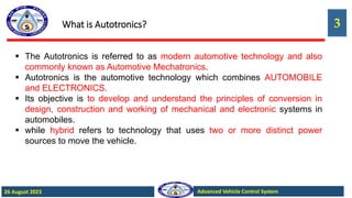
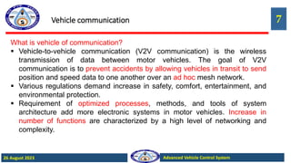
Vehicle communication
In today’s vehicles, virtually all the ECUs are networked directly or indirectly
(e.g. via gateways) with each other.
Gateways facilitate the exchange of data between different communication
systems and beyond vehicle limits. Use of 360° camera for automatic park-
assist also enables the driver to have a bird’s-eye view of the vehicle in the
infotainment-system display. [Connection to radio systems and the Internet is
an example of communication beyond vehicle limits.]
In the beginning of the development of communication systems, logic
functions were distributed to many individual ECUs [function-specific ECUs]
in the vehicle. This means that virtually every function had its own ECU.](https://image.slidesharecdn.com/autotronics-230826155216-9a34a378/85/Autotronics-pptx-9-320.jpg)
![10
Advanced Vehicle Control System
26 August 2023
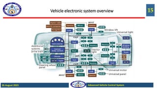
Vehicle communication
Later when the number of functions increased sharply, new functions
were frequently integrated in ECUs that already existed in the vehicle.
Integration of ‘parking-assist function’ in the “Body Control Module” is
an example. [BCM is responsible for controlling and monitoring the
functions and components of the body electronics like ‘light-actuator
technology’ ‘door-actuator technology.’]
The new development is called “Functionally distributed E/E
architectures”.](https://image.slidesharecdn.com/autotronics-230826155216-9a34a378/85/Autotronics-pptx-10-320.jpg)
![11
Advanced Vehicle Control System
26 August 2023
Vehicle communication
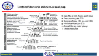
Later, to manage dependencies of the functions within the individual domains
increased sharply, “domain-centralized” and “cross-domain-centralized” E/E
architectures. [Domain refers to the grouping of similar functions. Examples of
domain are body control, infotainment, driver assistance etc.] An example of
cross-domain function is “Vehicle Motion Control”. In this, sensors, actuators,
and functions from the “Powertrain” and “Chassis and Safety” domains interact
directly with each other.
The next step would be Vehicle-centralized E/E architectures in which the
vehicle is in particular characterized by a high degree of automation, networked
systems [both vehicle-internal and vehicle-external] and by multimedia and
infotainment applications. In this architecture, all the logic are to be brought
together on a powerful central vehicle computer. All the functional interfaces
would then be located within this central vehicle computer.](https://image.slidesharecdn.com/autotronics-230826155216-9a34a378/85/Autotronics-pptx-11-320.jpg)

![14
Advanced Vehicle Control System
26 August 2023
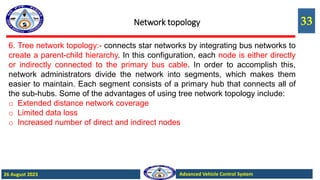
Network topology
Network topology:- With the tremendous speed at which computing
technology is advancing, the complexity of automotive control system is
ever increasing.
The individual components need to be networked so that the multitude of
information that is managed by the individual systems can also be used
elsewhere throughout the system.
A network is a system in which a group of elements can exchange
information via a transportation medium. [If the elements are visualized as
nodes and the communication relationships as lines, a picture is created
of a network where many nodes are related to several other nodes.]
The nodes in a communication network are also often referred to as
network subscribers or stations.](https://image.slidesharecdn.com/autotronics-230826155216-9a34a378/85/Autotronics-pptx-14-320.jpg)


![21
Advanced Vehicle Control System
26 August 2023
Cont.
Automotive Networking and Bus system
Electrical and electronic systems in motor vehicles
influence and complement each other. For example,
signal lines were used in previous injection and ignition
systems in order to simplify communication between
these two systems.
Rapid increase in the number of electronic systems
increased the information that was being exchanged.
This increased the number of signal lines and plug
connections required. Transfer of large volumes of data,
from different sources, became easier when a serial
bus system was first used in a vehicle [Mercedes-Benz
500E] in 1991.](https://image.slidesharecdn.com/autotronics-230826155216-9a34a378/85/Autotronics-pptx-21-320.jpg)
![22
Advanced Vehicle Control System
26 August 2023
Requirements for bus systems
Data transfer rate [Transfer rate, Data rate or Bit rate]
o This variable specifies the volume of data that is transmitted during a time unit
[bits/seconds]. The required data rate is dependent on the application. For
example, to switch on and off the air-conditioning compressor a slower transfer
rate is required where as to transfer audio signals a higher rate is required.
Interference immunity
o Ideally, the data should be transferred without interference. However, this cannot
be guaranteed in a motor vehicle because of electromagnetic effects [EMI]. The
interference immunity requirements depend on the safety relevance of the
electronic systems concerned. Lesser requirements are made of comfort and
convenience systems than the ABS.](https://image.slidesharecdn.com/autotronics-230826155216-9a34a378/85/Autotronics-pptx-22-320.jpg)
![23
Advanced Vehicle Control System
26 August 2023
Requirements for bus systems
Real-time capability
o This requirement guarantees that the system results are calculated within a
fixed time interval. The duration of the time interval depends on the application.
[Eg. The ABS must react to the incipient locking of a wheel within a few
milliseconds (wheel speed reduction), whereas response times of 100ms are
adequate for actuating the power-window motor.] Human beings cannot
perceive delay periods of less than 100ms. If signals from other control units
are needed for functions (e.g. a torque reduction request during a shift
operation), the bus system must transmit the data at a faster rate and with a
smaller time delay so that the overall system complies with the specified real-
time requirements.](https://image.slidesharecdn.com/autotronics-230826155216-9a34a378/85/Autotronics-pptx-23-320.jpg)
![24
Advanced Vehicle Control System
26 August 2023
Requirements for bus systems
Number of network nodes
o The maximum number of nodes
to be integrated varies for
different areas of vehicle
operation. The number of nodes
for comfort and convenience
systems may be high due to
servomotor networking (e.g. seat
adjustment) and intelligent
sensors (e.g. rain sensors).
Several identical busses can be
used if necessary.
Classification of bus Systems
CLASS A
Transfer rate Low data rates [up to 10 kbit/s]
Applications Actuator and sensor networking
Representative LIN
CLASS B
Transfer rate Average data rates [up to 125 kbit/s]
Applications
Complex mechanisms for error handling, control unit networking in
the comfort functions
Representative Low speed CAN [CAN B]
CLASS C
Transfer rate High data rates [up to 1 Mbit/s]
Applications
Real-time requirements, control unit networking in the drive and
running gear functions
Representative High speed CAN
CLASS C+
Transfer rate Extremely high data rates [up to 10 Mbit/s]
Applications
Real-time requirements, control unit networking in the drive and
running gear functions
Representative FlexRay
CLASS D
Transfer rate Extremely high data rates [up to 10 Mbit/s]
Applications Control unit networking in the telematics and multi-media functions
Representative MOS](https://image.slidesharecdn.com/autotronics-230826155216-9a34a378/85/Autotronics-pptx-24-320.jpg)
![25
Advanced Vehicle Control System
26 August 2023
Requirements for bus systems
Do a comparative study of the following bus systems: CAN-A, CAN-B, LIN, & TP
Network applications in a vehicle
The overall vehicle system can be divided into four domains or functional areas from
the point of view or electrics/electronics:
o Drivetrain
o Chassis
o Interior and
o Telematics
o In the drivetrain and chassis domains, the emphasis is primarily on real-time applications. A system is said to
be having real-time capability if its response times are adequate for the task in hand. [example scenario;
rapid ignition timing advance in the ‘Motronic’ after a request from the traction-control system for reducing
torque and therefore preventing the wheel from spinning.] In the interior domain, the main focus is on
multiplex aspects in networking. Mainly multimedia and infotainment applications are networked in the
telematics domain.](https://image.slidesharecdn.com/autotronics-230826155216-9a34a378/85/Autotronics-pptx-25-320.jpg)
![26
Advanced Vehicle Control System
26 August 2023
Requirements for bus systems
Do a comparative study of the following bus systems: CAN-A, CAN-B, LIN, & TP
Real time applications
The drivetrain and chassis systems are assigned to class C network. [These require
fast transfer rates in order to ensure the real-time behavior that is required for these
applications.] These requirements are met by the CAN bus with a transfer rate of 500 kBaud (high-speed
CAN). [Baud is the rate at which information is transferred. 500kBaud means that the port is capable of
transferring a maximum of 500 kbits per second].Examples of systems that run on this network:
o Engine-management system [Motronic or electronic diesel control, EDC]
o Transmission control
o Antilock brake systems, ABS
o Vehicle dynamics control [e.g. electronic stability program, ESP]
o Chassis control systems [e.g. active body control, ABC]
o Support systems [e.g. adaptive cruise control, ACC]](https://image.slidesharecdn.com/autotronics-230826155216-9a34a378/85/Autotronics-pptx-26-320.jpg)


![30
Advanced Vehicle Control System
26 August 2023
Network topology
3. Ring network topology
Media Oriented System Transport [MOST] is a
software protocol and hardware architecture. MOST
is optimized for automotive infotainment [multimedia
networking] system. MOST buses uses ring
topology and synchronous data communication to
transport audio, video, voice and data signals via
plastic optical fiber (POF) (MOST25, MOST150) or
electrical conductor (MOST50, MOST150) physical
layers. It provides an optical solution for automotive
peripherals like car radios, CD and DVD players,
and GPS navigation systems.](https://image.slidesharecdn.com/autotronics-230826155216-9a34a378/85/Autotronics-pptx-30-320.jpg)


![50
Advanced Vehicle Control System
26 August 2023
Multiplexing
Illustration of switching scheme
As shown in the illustration of switching
scheme, whenever the input switch
connects the computer to an
appropriate input, the output switch
connects the computer to the
corresponding display or actuator. IN a
real time control system, the actual
switching is done by means of a solid-
state electronic switching device. The
one at the input side is called a
multiplexer [MUX] that selects one of
several inputs for each output. The
device at the output side is called a
demultiplexer [DMUX].](https://image.slidesharecdn.com/autotronics-230826155216-9a34a378/85/Autotronics-pptx-50-320.jpg)

![52
Advanced Vehicle Control System
26 August 2023
Mechatronics
Besides systems and components, mechatronics are also playing an
increasingly vital role in the field of automotive micromechanics.
Hot-film air-mass meters and yaw-rate sensors are two examples.
CRDI system may be considered for an example of application of
mechatronics at system level. In the common-rail system, pressure
generation and fuel injection are separated from each other.
A high-pressure accumulator [the common rail] stores constantly the fuel
pressure required for each of the engine’s operating states.](https://image.slidesharecdn.com/autotronics-230826155216-9a34a378/85/Autotronics-pptx-52-320.jpg)

![54
Advanced Vehicle Control System
26 August 2023
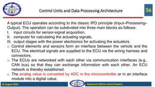
Control Units and Data Processing Architecture
The electronic components of a vehicle control system are accommodated
in an electronic control unit [ECU]. The number of ECUs in a vehicle has
increased sharply in the recent years, as more and more systems are being
electronically controlled. The following are some of the systems which use
ECUs, on a typical automobile.
• Engine management
• Transmission control,
• Driving-dynamics control (electronic stability program with antilock
braking system and traction control system),
• Vehicle power supply control unit,
• A/C control unit,
• Door control unit](https://image.slidesharecdn.com/autotronics-230826155216-9a34a378/85/Autotronics-pptx-54-320.jpg)

![58
Advanced Vehicle Control System
26 August 2023
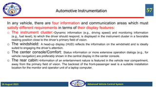
Automotive Instrumentation
Earlier instrument cluster First gen instrument cluster Modern instrument cluster with LCDs
The graphics module in the instrument cluster enables an indication of driver-related functions [for example,
service intervals, check functions covering the vehicle’s operating state and vehicle diagnostics etc.] They
can also show route-direction information from the navigation system. In modules in which surface area is
small, instead of digitized map excerpts, only route-direction symbols [for example turn instructions or
intersection symbols] appear in the display](https://image.slidesharecdn.com/autotronics-230826155216-9a34a378/85/Autotronics-pptx-58-320.jpg)

![60
Advanced Vehicle Control System
26 August 2023
Automotive Instrumentation
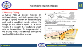
Head-up Display
Conventional instrument clusters are situated at
a viewing distance of 0.8 to 1.2 m. In order to
read information in the area of the instrument
cluster, the driver must adjust his or her eyes
from long distance (observing the road scene) to
the short viewing distance for the instrument.
This a customization process usually requires,
depending on the driver’s age, 0.3 to 0.5 s. A
head-up display, or heads-up display [HUD]
presents data without requiring users to look
away from their usual viewpoints. This is made
possible by using a transparent display onto
which information are projected. HUD mounted on to the dashboard](https://image.slidesharecdn.com/autotronics-230826155216-9a34a378/85/Autotronics-pptx-60-320.jpg)

![63
Advanced Vehicle Control System
26 August 2023
Automotive Instrumentation
Head-up Display
“Augmented-reality” head-up displays are more
sophisticated. They use laser or a “Digital Light
Projection” [DLP] module to generate the image.
[In DLP, images are generated by micromechanical
elements.] Augmented-reality head-up displays are
characterized by a larger projection field. This enables the
system to display the warning of an obstacle in the driver’s field
of vision and at the virtual distance in which it is located in
nature. [With this system, for example, route-direction information
can be displayed at an intersection precisely where the junction
suggested by the navigation system is situated; at an
expressway/highway exit the arrow for recommending the exit
can be positioned on the deceleration lane.]
Augmented-reality head-up display](https://image.slidesharecdn.com/autotronics-230826155216-9a34a378/85/Autotronics-pptx-63-320.jpg)
![64
Advanced Vehicle Control System
26 August 2023
Electronic engine control system,
COMPUTER CONTROLLED FUEL SUPPLY: Electronic fuel control overview, drive cycle,
advantages, basic system operation, controller inputs and outputs, engine control sequence,
case studies of advanced fuel supply systems
COMMON TECHNOLOGY: Engine management system, ABS, traction control, wheel
spin regulation, stability control, OBD, diagnostic tools and equipment, head-on
displays, SRS.
SENSORS AND ACTUATORS: Types of sensors: a sensor for speed, throttle position,
exhaust oxygen level, manifold pressure, crankshaft position, coolant temperature, exhaust
temperature, air mass flow, knock sensor, flex-fuel sensor, and other sensors for engine
application. Sensors are used for vehicle motion control, LIDAR, digital vision camera, and other
instruments used for vehicle environmental information. Actuators used in fuel injection, EGR
control, VVT, instrument cluster, ignition coil operator. Relays.
INTELLIGENT SYSTEMS: Intelligent Transportation Systems [ITSs], ITS architecture,
Control by wire, Autonomous vehicles, connected vehicles.](https://image.slidesharecdn.com/autotronics-230826155216-9a34a378/85/Autotronics-pptx-64-320.jpg)


![[English Version]Maker-Ray Product Brochure V3 .pdf](https://cdn.slidesharecdn.com/ss_thumbnails/englishversionmaker-rayproductbrochurev3-260113094444-0156dbdc-thumbnail.jpg?width=640&height=640&fit=bounds)


