

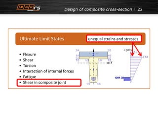
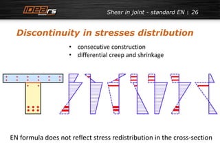

![33
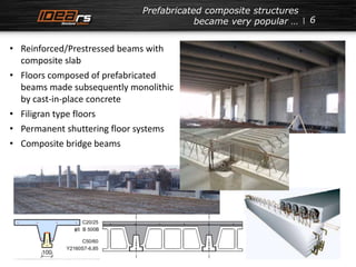
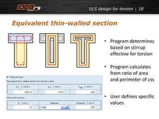
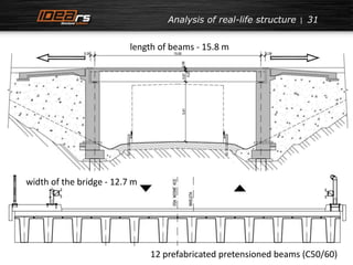
shear stresses at distance
1.1 m from support
1200
1000
800
600
400
200
0
100 150 200 250 300 350 400
Shear stress [kPa]
Shear force [kN]
β-2 dx-2
β = 1,0
β ≤ 1,0
cracks
β=0,57](https://image.slidesharecdn.com/ec2designofcomposite-141215043432-conversion-gate01/85/Eurocode-2-design-of-composite-concrete-33-320.jpg)
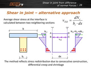
![34
1200
1000
800
600
400
200
0
β-2 dx-2
β-1-1 dx-1-1
β = 1,0
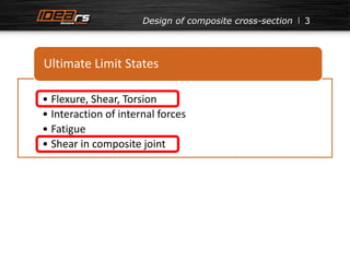
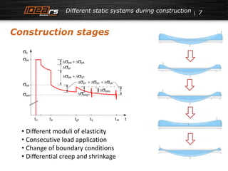
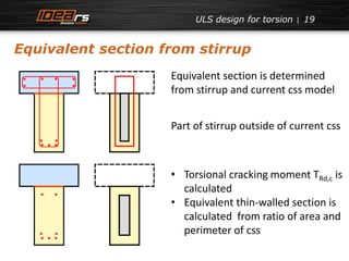
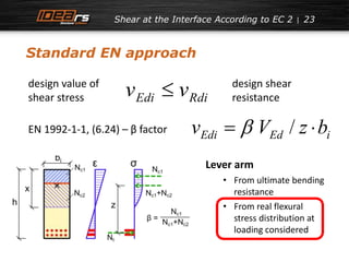
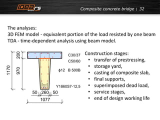
EN 1992-1-1
100 150 200 250 300 350 400
Shear stress [kPa]
Shear force [kN]
β = 1,0
β ≤ 1,0
cracks
cracks
β=0,57
EN 1992-2
shear stresses at distance
1.1 m from support](https://image.slidesharecdn.com/ec2designofcomposite-141215043432-conversion-gate01/85/Eurocode-2-design-of-composite-concrete-34-320.jpg)
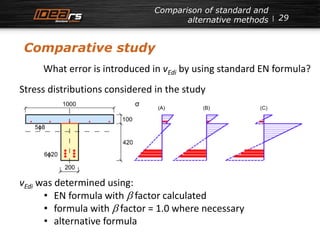
![35
1200
1000
800
600
400
200
0
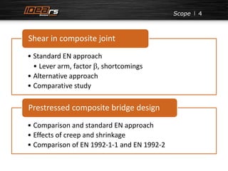
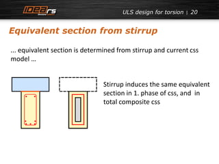
dx-1-1 dx-2
β-1-1 β-2
dx no cr-2 dx lin-2
dx lin-1-1
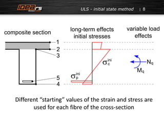
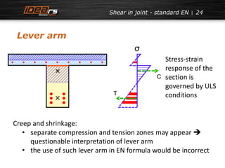
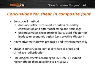
shear stresses at distance
100 150 200 250 300 350 400
Shear stress [kPa]
Shear force [kN]
cracks
cracks
1.1 m from support](https://image.slidesharecdn.com/ec2designofcomposite-141215043432-conversion-gate01/85/Eurocode-2-design-of-composite-concrete-35-320.jpg)
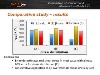
![36
30
25
20
15
10
5
0
0
-1
-2
-3
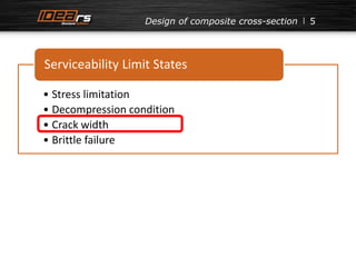
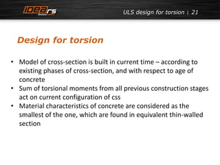
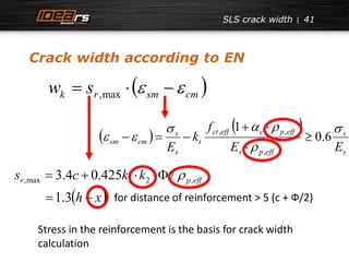
σc,b-2
σc,b-1-1
σs,t-2
σs,t-1-1
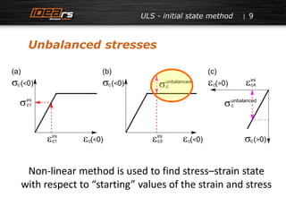
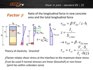
normal stresses at distance
1.1 m from support
1 10 100 1000 10000 100000
Steel stress [MPa]
Concrete stress [MPa]
Age of prefabricated beam [days]](https://image.slidesharecdn.com/ec2designofcomposite-141215043432-conversion-gate01/85/Eurocode-2-design-of-composite-concrete-36-320.jpg)
![Casting of composite slab after 20 years 37
60
50
40
30
20
10
0
0
-0.5
-1
-1.5
-2
1 10 100 1000 10000 100000
Steel stress [MPa]
Concrete stress [MPa]
Slab age [days]
σc,b-2
σc,b-1-1
σs,t-2
σs,t-1-1](https://image.slidesharecdn.com/ec2designofcomposite-141215043432-conversion-gate01/85/Eurocode-2-design-of-composite-concrete-37-320.jpg)
![Casting of composite slab after 20 years 38
1200
1000
800
600
400
200
0
dx-1-1 dx-2
β-1-1 β-2
dx lin-1-1 dx lin-2
β = 1,0
cracks cracks
100 150 200 250 300 350 400
Shear stress [kPa]
Shear force [kN]](https://image.slidesharecdn.com/ec2designofcomposite-141215043432-conversion-gate01/85/Eurocode-2-design-of-composite-concrete-38-320.jpg)
![39
Comparison composite slab after
60 days/20 years
1200
1000
800
600
400
200
0
dx 60 days-2
dx 60 days-1-1
dx 20 years-2
dx 20 years-1-1
100 150 200 250 300 350 400
Shear stress [kPa]
Shear force [kN]](https://image.slidesharecdn.com/ec2designofcomposite-141215043432-conversion-gate01/85/Eurocode-2-design-of-composite-concrete-39-320.jpg)
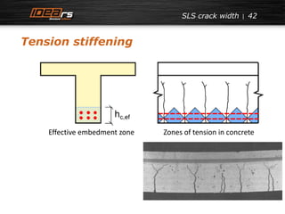
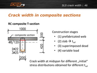
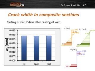
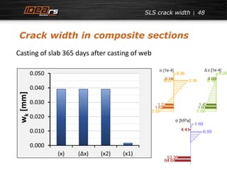
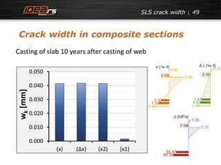
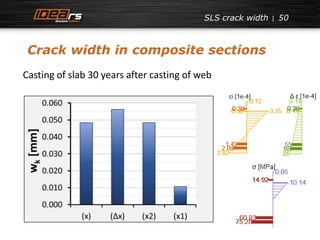
![SLS crack width
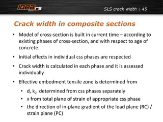
Crack width in composite sections
51
RC composite T-section (after 100 years)
Casting of composite slab [days]
Crack in slab [mm]
Crack in web [mm]](https://image.slidesharecdn.com/ec2designofcomposite-141215043432-conversion-gate01/85/Eurocode-2-design-of-composite-concrete-51-320.jpg)


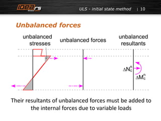
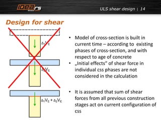
The document presents an analysis of the design of composite concrete structures, focusing on ultimate limit states such as flexure, shear, and torsion. It highlights the shortcomings of current standards (EN) in predicting shear stresses and proposes an alternative method that incorporates stress redistribution effects. Additionally, it discusses crack width calculations and emphasizes the need for a more efficient design tool for engineers.