The document covers fundamental concepts in electrical technology, including electromotive force (emf), potential, current, and the differences between direct current (DC) and alternating current (AC). It discusses essential AC concepts such as cycles, frequency, phasors, and power calculations, emphasizing the distinction between active, reactive, and apparent power. Additionally, it details earthing methods and the use of megger for insulation testing, highlighting their construction and functioning.


![AC Imaginary (Reactive) Power (Q)
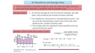
• The reactive power (Q) is the power that is exchanged (travel back and
forth) between reactive components (inductors and capacitors).
• The formulas look similar to those used by the active power, but use
reactance instead of resistances.
• Units: Volts-Amps-Reactive (VAR)
• Q is negative for a capacitor by convention and positive for inductor as
an inductive load consumes the reactive power while capacitive load
generates the reactive power.
𝑄 = 𝐼2
𝑋 =
𝑉2
𝑋
= VI sin Φ [VAR]
WARNING! #1 mistake with AC power calculations!
The Voltage in the above equation is the Voltage drop across the reactance, not
across the entire circuit!](https://image.slidesharecdn.com/et1-241011074535-57a71fc9/85/Electrical-Technology-module-1-ppt-1-pdf-18-320.jpg)
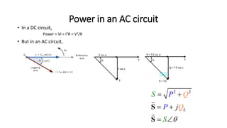
![AC Apparent Power (S)
• The Apparent Power (S) is the power that “appears” to flow to the
load. It is the complex combination of true or active power and
reactive power
• The magnitude of apparent power can be calculated using similar
formulas to those for active or reactive power:
• Units: Volts-Amps (VA)
• V & I are the magnitudes, not the phasors.
2
2
[VA]
V
S VI I Z
Z
](https://image.slidesharecdn.com/et1-241011074535-57a71fc9/85/Electrical-Technology-module-1-ppt-1-pdf-19-320.jpg)