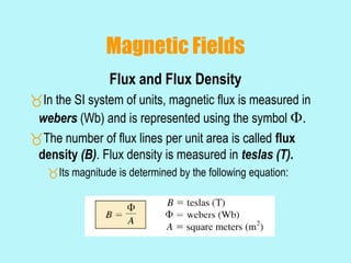
Chapter 1 – Magnetic circuits
MAGNETIC CIRCUITS
Electrical current flowing along a wire
creates a magnetic field around the wire, as
shown in Fig. That magnetic field can be
visualized by showing lines of magnetic flux,
which are represented with the symbol φ.The
direction of that field that can be
determinedusing the “right hand rule”
Comparison of Electric and Magnetic circuits
Units of Magnetic and Electric circuits
11.1 - Introduction
Inductors have a number of response characteristics
similar to those of the capacitor.
The inductor exhibits its true characteristics only
when a change in voltage or current is made in the
network.
11.2 - Magnetic Fields
In the region surrounding a permanent magnet
there exists a magnetic field, which can be
represented by magnetic flux lines similar to
electric flux lines.
Magnetic flux lines differ from electric flux lines
in that they don’t have an origin or termination
point.
Magnetic flux lines radiate from the north pole to
the south pole through the magnetic bar.
Magnetic Fields
Continuous magnetic flux lines will strive to occupy as
small an area as possible.
The strength of a magnetic field in a given region is
directly related to the density of flux lines in that region.
If unlike poles of two permanent magnets are brought
together the magnets will attract, and the flux distribution
will be as shown below.
Magnetic Fields
If like poles are brought
together, the magnets will
repel, and the flux distribution
will be as shown.
If a nonmagnetic material,
such as glass or copper, is
placed in the flux paths
surrounding a permanent
magnet, there will be an
almost unnoticeable change in
the flux distribution.
Magnetic Fields
If a magnetic material, such as soft iron, is placed in the flux path,
the flux lines will pass through the soft iron rather than the
surrounding air because the flux lines pass with greater ease
through magnetic materials than through air.
This principle is put to use in the shielding of sensitive electrical
elements and instruments that can be affected by stray magnetic
fields.
Magnetic Fields
The direction of the magnetic flux lines can be found by
placing the thumb of the right hand in the direction of
conventional current flow and noting the direction of the
fingers (commonly called the right hand rule).
Magnetic Fields
Flux and Flux Density
In the SI system of units, magnetic flux is measured in
webers (Wb) and is represented using the symbol .
The number of flux lines per unit area is called flux
density (B). Flux density is measured in teslas (T).
Its magnitude is determined by the following equation:
Magnetic Fields
Permeability
If cores of different materials with the same physical
dimensions are used in the electromagnet, the strength of the
magnet will vary in accordance with the core used.
The variation in strength is due to the number of flux lines
passing through the core.
Magnetic material is material in which flux lines can readily be
created and is said to have high permeability.
Permeability () is a measure of the ease with which
magnetic flux lines can be established in the material.
Magnetic Fields
Permeability
Permeability of free space 0 (vacuum) is
Materials that have permeability slightly less than
that of free space are said to be diamagnetic and
those with permeability slightly greater than that of
free space are said to be paramagnetic.
MA
Wb
104 7
0

 

Magnetic Fields
Permeability
Magnetic materials, such as iron, nickel, steel and
alloys of these materials, have permeability hundreds
and even thousands of times that of free space and are
referred to as ferromagnetic.
The ratio of the permeability of a material to that of
free space is called relative permeability.
0

 r
11.3 – Inductance
Inductors are designed to set up a strong
magnetic field linking the unit, whereas capacitors
are designed to set up a strong electric field
between the plates.
Inductance is measure in Henries (H).
One henry is the inductance level that will establish
a voltage of 1 volt across the coil due to a chance in
current of 1 A/s through the coil.
Inductance
Inductor construction and inductance
l
AN
L
2


(H)henriesininductance
(m)length
)(marea
(t)turnsofnumber
m)(Wb/Atypermeabili
2





L
l
A
N

11.4 – Induced Voltage
If a conductor is moved through a magnetic field so that
it cuts magnetic lines of flux, a voltage will be induced
across the conductor.
Induced Voltage
Faraday’s law of electromagnetic induction
The greater the number of flux lines cut per unit time (by
increasing the speed with which the conductor passes through
the field), or the stronger the magnetic field strength (for the
same traversing speed), the greater will be the induced voltage
across the conductor.
If the conductor is held fixed and the magnetic field is moved
so that its flux lines cut the conductor, the same effect will be
produced.
Induced Voltage
Faraday’s law of electromagnetic induction
If a coil of N turns is placed in the region of the
changing flux, as in the figure below, a voltage will be
induced across the coil as determined by Faraday’s
Law.
Induced Voltage
Lenz’s law
An induced effect is always such as to oppose
the cause that produced it.
Induced Voltage
The inductance of a coil is also a measure of the
change in flux linking a coil due to a change in
current through the coil
N is the number of turns,  is the flux in webers, and
i is the current through the coil
Induced Voltage
The larger the inductance of a coil (with N fixed), the larger will
be the instantaneous change in flux linking the coil due to the
instantaneous change in the current through the coil.
The voltage across an inductor is directly related to the
inductance L and the instantaneous rate of change through the
coil. The greater the rate of change of current through the coil,
the greater the induced voltage.
V)(volts,
dt
di
Lv L
L 
11.5 – R-L Transients: The Storage
Phase
The changing voltage and current that result
during the storing of energy in the form of a
magnetic field by an inductor in a dc circuit.
The instant the switch is closed, inductance in
the coil will prevent an instantaneous change in
the current through the coil.
The potential drop across the coil VL, will equal the
impressed voltage E as determined by Kirchhoff’s
voltage law.
R-L Transients: The Storage Phase
An ideal inductor (Rl = 0 ) assumes a short-circuit
equivalent in a dc network once steady-state conditions
have been established.
The storage phase has passed and steady-state conditions
have been established once a period of time equal to five
time constants has occurred.
The current cannot change instantaneously in an inductive
network.
The inductor takes on the characteristics of an open circuit
at the instant the switch is closed.
The inductor takes on the characteristics of a short circuit
when steady-state conditions have been established.
11.6 – Initial Values
Since the current through a coil cannot change
instantaneously, the current through a coil will begin the
transient phase at the initial value established by the network
before the switch was closed
The current will then pass through the transient phase until it
reaches the steady-state (or final) level after about 5 time
constants
The steady-state level of the inductor current can be found by
substituting its short-circuit equivalent (or Rl for the practical
equivalent)
Initial Values
The drawing of the
waveform for the current iL
from the initial value to a
final value.
11.7 – R-L Transients: The Release Phase
In R-L circuits, the energy is stored in the form of a
magnetic field established by the current through the
coil.
An isolated inductor cannot continue to store energy
since the absence of a closed path would cause the
current to drop to zero, releasing the energy stored in
the form of a magnetic field.
R-L Transients: The Release Phase
 Analyzing the R-L circuit in the same manner as the R-
C circuit.
When a switch is closed, the voltage across the resistor R2 is
E volts, and the R-L branch will respond in the change in the
current di/dt of the equation vL = L(di/dt) would establish a high
voltage vL across the coil.
11.8 – Thévenin Equivalent:  = L/RTh
If the circuit does not have the basic series form, it is
necessary to find the Thévenin equivalent circuit
11.9 – Instantaneous Values
 The instantaneous values of any voltage or current
can be determined by simply inserting t into the
equation and using a calculator or table to determine
the magnitude of the exponential term.
Storage cycle:
Decay cycle:
s)(seconds,log
fL
fi
e
Ii
II
t



s)(seconds,log
L
i
e
v
V
t 
11.10 Average Induced Voltage
For inductors, the average induced voltage is
defined by
V)(volts,av
t
i
Lv L
L



11.11 – Inductors in Series and in
Parallel
 Inductors, like resistors and capacitors, can be placed
in series
 Increasing levels of inductance can be obtained by placing
inductors in series
Inductors in Series and in Parallel
Inductors, like resistors and capacitors, can be placed
in parallel.
 Decreasing levels of inductance can be obtained by placing
inductors in parallel.
11.12 – Steady State Conditions
 An inductor can be replaced by a short circuit in a dc
circuit after a period of time greater than five time
constants have passed.
 Assuming that all of the currents and voltages have
reached their final values, the current through each
inductor can be found by replacing each inductor with
a short circuit.
11.13 – Energy Stored by an
Inductor
 The ideal inductor, like the ideal capacitor, does not
dissipate the electrical energy supplied to it. It stores
the energy in the form of a magnetic field.
UNIT-4 & UNIT-5
DC MACHINES
DC MACHINES
Maxwell’s Cork screw Rule :
Hold the cork screw in yr right
hand and rotate it in clockwise
in such a way that it advances in
the direction of current. Then
the direction in which the hand
rotates will be the direction of
magnetic lines of force .
Fleming’s left hand rule
Used to determine the direction of force acting
on a current carrying conductor placed in a
magnetic field .
The middle finger , the fore finger and thumb of
the left hand are kept at right angles to one
another .
The middle finger represent the direction
of current
The fore finger represent the direction of
magnetic field
The thumb will indicate the direction of
force acting on the conductor .
This rule is used in motors.
Fleming’s Right hand rule
Used to determine the direction of emf induced
in a conductor
The middle finger , the fore finger and thumb of
the left hand are kept at right angles to one
another.
The fore finger represent the direction
of magnetic field
The thumb represent the direction of
motion of the conductor
The middle finger will indicate the
direction of the inducted emf .
This rule is used in DC Generators
Len’s Law
The direction of induced emf is given by
Lenz’s law .
According to this law, the induced emf will
be acting in such a way so as to oppose the
very cause of production of it .
e = -N (dØ/dt) volts
DC Generator
Mechanical energy is converted to electric
energy
Three requirements are essential
1. Conductors
2. Magnetic field
3. Mechanical energy
Working principle
A generator works on the principles of
Faraday’s law of electromagnetic induction
Whenever a conductor is moved in the
magnetic field , an emf is induced and the
magnitude of the induced emf is directly
proportional to the rate of change of flux
linkage.
This emf causes a current flow if the
conductor circuit is closed .
DC Machine
Commutator
Sectional view of a DC machine
Construction of DC Generator
Field system
Armature core
Armature
winding
Commutator
Brushes
Field winding
Rotor and rotor winding
Working principle of DC motor
Force in DC motor
Armature winding
There are 2 types of winding
Lap and Wave winding
Lap winding
A = P
The armature
windings are
divided into
no. of sections
equal to the no
of poles
Wave winding
A = 2
It is used in low
current output
and high voltage.
2 brushes
Field system
It is for uniform magnetic field within
which the armature rotates.
Electromagnets are preferred in
comparison with permanent magnets
They are cheap , smaller in size ,
produce greater magnetic effect and
Field strength can be varied
Field system consists of the
following parts
Yoke
Pole cores
Pole shoes
Field coils
Armature core
The armature core is cylindrical
High permeability silicon steel
stampings
Impregnated
Lamination is to reduce the eddy
current loss
Commutator
Connect with external circuit
Converts ac into unidirectional current
Cylindrical in shape
Made of wedge shaped copper segments
Segments are insulated from each other
Each commutator segment is connected to
armature conductors by means of a cu strip called
riser.
No of segments equal to no of coils
Carbon brush
Carbon brushes are used in DC machines
because they are soft materials
It does not generate spikes when they contact
commutator
To deliver the current thro armature
Carbon is used for brushes because it has
negative temperature coefficient of resistance
Self lubricating , takes its shape , improving
area of contact
Brush rock and holder
Carbon brush
Brush leads (pig tails)
Brush rocker ( brush gear )
Front end cover
Rear end cover
Cooling fan
Bearing
Terminal box
EMF equation
Let,
Ø= flux per pole in weber
Z = Total number of conductor
P = Number of poles
A = Number of parallel paths
N =armature speed in rpm
Eg = emf generated in any on of the
parallel path
EMF equation
Flux cut by 1 conductor
in 1 revolution = P * φ
Flux cut by 1 conductor in
60 sec = P φ N /60
Avg emf generated in 1
conductor = PφN/60
Number of conductors in
each parallel path = Z /A
Eg = PφNZ/60A
DC generators are generally classified
according to their method of excitation .
Separately excited DC generator
Self excited D C generator
Types of DC Generator
Further classification of DC Generator
Series wound generator
Shunt wound generator
Compound wound generator
Short shunt & Long shunt
Cumulatively compound
&
Differentially compound
No load saturation characteristic (Eo/If)
Internal or Total characteristic (E/ Ia)
External characteristic (V/I)
Characteristics
For appreciable generation of emf, the
field resistance must be always less
certain resistance, that resistance is
called as the critical resistance of the
machine .
Critical field resistance
Magnetic neutral axis :
It is perpendicular to the lines of force
between the two opposite adjacent poles.
Leading pole Tip (LPT) :
It is the end of the pole which first
comes in contact with the armature.
Trailing pole tip :
It is the end of the pole which comes in
contact later with the armature.
General terms used in Armature
reaction
Armature Reaction
Interaction of Main field flux with Armature
field flux
Effects of Armature Reaction
It decreases the efficiency of the machine
It produces sparking at the brushes
It produces a demagnetising effect on the
main poles
It reduces the emf induced
Self excited generators some times fail to
build up emf
Armature reaction remedies
1.Brushes must be shifted to the new position of
the MNA
2.Extra turns in the field winding
3.Slots are made on the tips to increase the
reluctance
4. The laminated cores of the shoe are staggered
5. In big machines the compensating winding at
pole shoes produces a flux which just opposes
the armature mmf flux automatically.
Commutation
The change in direction of current takes
place when the conductors are along the
brush axis .
During this reverse process brushes short
circuit that coil and undergone
commutation
Due to this sparking is produced and the
brushes will be damaged and also causes
voltage dropping.
Losses in DC Generators
1. Copper losses or variable losses
2. Stray losses or constant losses
Stray losses : consist of (a) iron losses or core
losses and (b) windage and friction losses .
Iron losses : occurs in the core of the machine
due to change of magnetic flux in the core .
Consist of hysteresis loss and eddy current
loss.
Hysteresis loss depends upon the frequency ,
Flux density , volume and type of the core .
Losses
Hysteresis loss depends upon the frequency ,
Flux density , volume and type of the core .
Eddy current losses : directly proportional to
the flux density , frequency , thickness of the
lamination .
Windage and friction losses are constant due to
the opposition of wind and friction .
Shunt Generators:
a. in electro plating
b. for battery recharging
c. as exciters for AC generators.
Applications
Series Generators :
A. As boosters
B. As lighting arc lamps
DC Motors
Converts Electrical energy into Mechanical
energy
Construction : Same for Generator and
motor
Working principle : Whenever a current
carrying conductor is placed in the
magnetic field , a force is set up on the
conductor.
Back emf
The induced emf in the rotating armature
conductors always acts in the opposite
direction of the supply voltage .
According to the Lenz’s law, the direction of the
induced emf is always so as to oppose the
cause producing it .
In a DC motor , the supply voltage is the cause
and hence this induced emf opposes the
supply voltage.
Classification of DC motors
DC motors are mainly classified into
three types as listed below:
Shunt motor
Series motor
Compound motor
Differential compound
Cumulative compound
Torque
The turning or twisting force about an
axis is called torque .
P = T * 2 πN/ 60
Eb Ia = Ta * 2 πN/ 60
T ∞ φ I a
Ta ∞ I2a
Characteristic of DC motors
T/ Ia characteristic
N/ I a characteristic
N/T characteristic
According to the speed equation of a dc motor
N ∞ Eb/φ
∞ V- Ia Ra/ φ
Thus speed can be controlled by-
Flux control method: By Changing the flux by
controlling the current through the field
winding.
Armature control method: By Changing the
armature resistance which in turn changes
the voltage applied across the armature
Speed control of DC motors
Advantages of flux control:
It provides relatively smooth and easy control
Speed control above rated speed is possible
As the field winding resistance is high the field current
is small. Power loss in the external resistance is small .
Hence this method is economical
Disadvantages:
Flux can be increased only upto its rated value
High speed affects the commutation, motor operation
becomes unstable
Flux control
Armature voltage control method
The speed is directly proportional to the voltage
applied across the armature .
Voltage across armature can be controlled by
adding a variable resistance in series with the
armature
Potential divider control :
If the speed control from zero to the rated speed is
required , by rheostatic method then the voltage
across the armature can be varied by connecting
rheostat in a potential divider arrangement .
Starters for DC motors
Needed to limit the starting current .
1. Two point starter
2. Three point starter
3. Four point starter
To determine the efficiency of as DC motor , the output and
input should be known.
There are two methods.
The load test or The direct method
The indirect method
Direct method: In this method , the efficiency is determined
by knowing the input and output power of the motor.
Indirect method: Swinburne’s test is an indirect method of
testing DC shunt machines to predetermine the effficency
, as a motor and as a Generator. In this method, efficiency
is calculated by determining the losses .
Testing of DC machines
Applications:
Shunt Motor:
Blowers and fans
Centrifugal and reciprocating pumps
Lathe machines
Machine tools
Milling machines
Drilling machines
Series Motor:
Cranes
Hoists , Elevators
Trolleys
Conveyors
Electric locomotives
Applications:
Cumulative compound Motor:
Rolling mills
Punches
Shears
Heavy planers
Elevators
Applications:
•
• Thanks
•

EE 8301 EMI

  • 1.
    Chapter 1 –Magnetic circuits
  • 2.
    MAGNETIC CIRCUITS Electrical currentflowing along a wire creates a magnetic field around the wire, as shown in Fig. That magnetic field can be visualized by showing lines of magnetic flux, which are represented with the symbol φ.The direction of that field that can be determinedusing the “right hand rule”
  • 3.
    Comparison of Electricand Magnetic circuits
  • 4.
    Units of Magneticand Electric circuits
  • 5.
    11.1 - Introduction Inductorshave a number of response characteristics similar to those of the capacitor. The inductor exhibits its true characteristics only when a change in voltage or current is made in the network.
  • 6.
    11.2 - MagneticFields In the region surrounding a permanent magnet there exists a magnetic field, which can be represented by magnetic flux lines similar to electric flux lines. Magnetic flux lines differ from electric flux lines in that they don’t have an origin or termination point. Magnetic flux lines radiate from the north pole to the south pole through the magnetic bar.
  • 7.
    Magnetic Fields Continuous magneticflux lines will strive to occupy as small an area as possible. The strength of a magnetic field in a given region is directly related to the density of flux lines in that region. If unlike poles of two permanent magnets are brought together the magnets will attract, and the flux distribution will be as shown below.
  • 8.
    Magnetic Fields If likepoles are brought together, the magnets will repel, and the flux distribution will be as shown. If a nonmagnetic material, such as glass or copper, is placed in the flux paths surrounding a permanent magnet, there will be an almost unnoticeable change in the flux distribution.
  • 9.
    Magnetic Fields If amagnetic material, such as soft iron, is placed in the flux path, the flux lines will pass through the soft iron rather than the surrounding air because the flux lines pass with greater ease through magnetic materials than through air. This principle is put to use in the shielding of sensitive electrical elements and instruments that can be affected by stray magnetic fields.
  • 10.
    Magnetic Fields The directionof the magnetic flux lines can be found by placing the thumb of the right hand in the direction of conventional current flow and noting the direction of the fingers (commonly called the right hand rule).
  • 11.
    Magnetic Fields Flux andFlux Density In the SI system of units, magnetic flux is measured in webers (Wb) and is represented using the symbol . The number of flux lines per unit area is called flux density (B). Flux density is measured in teslas (T). Its magnitude is determined by the following equation:
  • 12.
    Magnetic Fields Permeability If coresof different materials with the same physical dimensions are used in the electromagnet, the strength of the magnet will vary in accordance with the core used. The variation in strength is due to the number of flux lines passing through the core. Magnetic material is material in which flux lines can readily be created and is said to have high permeability. Permeability () is a measure of the ease with which magnetic flux lines can be established in the material.
  • 13.
    Magnetic Fields Permeability Permeability offree space 0 (vacuum) is Materials that have permeability slightly less than that of free space are said to be diamagnetic and those with permeability slightly greater than that of free space are said to be paramagnetic. MA Wb 104 7 0    
  • 14.
    Magnetic Fields Permeability Magnetic materials,such as iron, nickel, steel and alloys of these materials, have permeability hundreds and even thousands of times that of free space and are referred to as ferromagnetic. The ratio of the permeability of a material to that of free space is called relative permeability. 0   r
  • 15.
    11.3 – Inductance Inductorsare designed to set up a strong magnetic field linking the unit, whereas capacitors are designed to set up a strong electric field between the plates. Inductance is measure in Henries (H). One henry is the inductance level that will establish a voltage of 1 volt across the coil due to a chance in current of 1 A/s through the coil.
  • 16.
    Inductance Inductor construction andinductance l AN L 2   (H)henriesininductance (m)length )(marea (t)turnsofnumber m)(Wb/Atypermeabili 2      L l A N 
  • 17.
    11.4 – InducedVoltage If a conductor is moved through a magnetic field so that it cuts magnetic lines of flux, a voltage will be induced across the conductor.
  • 18.
    Induced Voltage Faraday’s lawof electromagnetic induction The greater the number of flux lines cut per unit time (by increasing the speed with which the conductor passes through the field), or the stronger the magnetic field strength (for the same traversing speed), the greater will be the induced voltage across the conductor. If the conductor is held fixed and the magnetic field is moved so that its flux lines cut the conductor, the same effect will be produced.
  • 19.
    Induced Voltage Faraday’s lawof electromagnetic induction If a coil of N turns is placed in the region of the changing flux, as in the figure below, a voltage will be induced across the coil as determined by Faraday’s Law.
  • 20.
    Induced Voltage Lenz’s law Aninduced effect is always such as to oppose the cause that produced it.
  • 21.
    Induced Voltage The inductanceof a coil is also a measure of the change in flux linking a coil due to a change in current through the coil N is the number of turns,  is the flux in webers, and i is the current through the coil
  • 22.
    Induced Voltage The largerthe inductance of a coil (with N fixed), the larger will be the instantaneous change in flux linking the coil due to the instantaneous change in the current through the coil. The voltage across an inductor is directly related to the inductance L and the instantaneous rate of change through the coil. The greater the rate of change of current through the coil, the greater the induced voltage. V)(volts, dt di Lv L L 
  • 23.
    11.5 – R-LTransients: The Storage Phase The changing voltage and current that result during the storing of energy in the form of a magnetic field by an inductor in a dc circuit. The instant the switch is closed, inductance in the coil will prevent an instantaneous change in the current through the coil. The potential drop across the coil VL, will equal the impressed voltage E as determined by Kirchhoff’s voltage law.
  • 24.
    R-L Transients: TheStorage Phase An ideal inductor (Rl = 0 ) assumes a short-circuit equivalent in a dc network once steady-state conditions have been established. The storage phase has passed and steady-state conditions have been established once a period of time equal to five time constants has occurred. The current cannot change instantaneously in an inductive network. The inductor takes on the characteristics of an open circuit at the instant the switch is closed. The inductor takes on the characteristics of a short circuit when steady-state conditions have been established.
  • 25.
    11.6 – InitialValues Since the current through a coil cannot change instantaneously, the current through a coil will begin the transient phase at the initial value established by the network before the switch was closed The current will then pass through the transient phase until it reaches the steady-state (or final) level after about 5 time constants The steady-state level of the inductor current can be found by substituting its short-circuit equivalent (or Rl for the practical equivalent)
  • 26.
    Initial Values The drawingof the waveform for the current iL from the initial value to a final value.
  • 27.
    11.7 – R-LTransients: The Release Phase In R-L circuits, the energy is stored in the form of a magnetic field established by the current through the coil. An isolated inductor cannot continue to store energy since the absence of a closed path would cause the current to drop to zero, releasing the energy stored in the form of a magnetic field.
  • 28.
    R-L Transients: TheRelease Phase  Analyzing the R-L circuit in the same manner as the R- C circuit. When a switch is closed, the voltage across the resistor R2 is E volts, and the R-L branch will respond in the change in the current di/dt of the equation vL = L(di/dt) would establish a high voltage vL across the coil.
  • 29.
    11.8 – ThéveninEquivalent:  = L/RTh If the circuit does not have the basic series form, it is necessary to find the Thévenin equivalent circuit
  • 30.
    11.9 – InstantaneousValues  The instantaneous values of any voltage or current can be determined by simply inserting t into the equation and using a calculator or table to determine the magnitude of the exponential term. Storage cycle: Decay cycle: s)(seconds,log fL fi e Ii II t    s)(seconds,log L i e v V t 
  • 31.
    11.10 Average InducedVoltage For inductors, the average induced voltage is defined by V)(volts,av t i Lv L L   
  • 32.
    11.11 – Inductorsin Series and in Parallel  Inductors, like resistors and capacitors, can be placed in series  Increasing levels of inductance can be obtained by placing inductors in series
  • 33.
    Inductors in Seriesand in Parallel Inductors, like resistors and capacitors, can be placed in parallel.  Decreasing levels of inductance can be obtained by placing inductors in parallel.
  • 34.
    11.12 – SteadyState Conditions  An inductor can be replaced by a short circuit in a dc circuit after a period of time greater than five time constants have passed.  Assuming that all of the currents and voltages have reached their final values, the current through each inductor can be found by replacing each inductor with a short circuit.
  • 35.
    11.13 – EnergyStored by an Inductor  The ideal inductor, like the ideal capacitor, does not dissipate the electrical energy supplied to it. It stores the energy in the form of a magnetic field.
  • 36.
  • 37.
  • 38.
  • 39.
    Maxwell’s Cork screwRule : Hold the cork screw in yr right hand and rotate it in clockwise in such a way that it advances in the direction of current. Then the direction in which the hand rotates will be the direction of magnetic lines of force .
  • 40.
  • 41.
    Fleming’s left handrule Used to determine the direction of force acting on a current carrying conductor placed in a magnetic field . The middle finger , the fore finger and thumb of the left hand are kept at right angles to one another . The middle finger represent the direction of current The fore finger represent the direction of magnetic field The thumb will indicate the direction of force acting on the conductor . This rule is used in motors.
  • 42.
  • 43.
    Fleming’s Right handrule Used to determine the direction of emf induced in a conductor The middle finger , the fore finger and thumb of the left hand are kept at right angles to one another. The fore finger represent the direction of magnetic field The thumb represent the direction of motion of the conductor The middle finger will indicate the direction of the inducted emf . This rule is used in DC Generators
  • 44.
    Len’s Law The directionof induced emf is given by Lenz’s law . According to this law, the induced emf will be acting in such a way so as to oppose the very cause of production of it . e = -N (dØ/dt) volts
  • 45.
    DC Generator Mechanical energyis converted to electric energy Three requirements are essential 1. Conductors 2. Magnetic field 3. Mechanical energy
  • 46.
    Working principle A generatorworks on the principles of Faraday’s law of electromagnetic induction Whenever a conductor is moved in the magnetic field , an emf is induced and the magnitude of the induced emf is directly proportional to the rate of change of flux linkage. This emf causes a current flow if the conductor circuit is closed .
  • 47.
  • 48.
    Sectional view ofa DC machine
  • 49.
    Construction of DCGenerator Field system Armature core Armature winding Commutator Brushes
  • 50.
  • 51.
  • 52.
  • 53.
  • 54.
  • 55.
    Armature winding There are2 types of winding Lap and Wave winding Lap winding A = P The armature windings are divided into no. of sections equal to the no of poles Wave winding A = 2 It is used in low current output and high voltage. 2 brushes
  • 56.
    Field system It isfor uniform magnetic field within which the armature rotates. Electromagnets are preferred in comparison with permanent magnets They are cheap , smaller in size , produce greater magnetic effect and Field strength can be varied
  • 57.
    Field system consistsof the following parts Yoke Pole cores Pole shoes Field coils
  • 58.
    Armature core The armaturecore is cylindrical High permeability silicon steel stampings Impregnated Lamination is to reduce the eddy current loss
  • 59.
    Commutator Connect with externalcircuit Converts ac into unidirectional current Cylindrical in shape Made of wedge shaped copper segments Segments are insulated from each other Each commutator segment is connected to armature conductors by means of a cu strip called riser. No of segments equal to no of coils
  • 60.
    Carbon brush Carbon brushesare used in DC machines because they are soft materials It does not generate spikes when they contact commutator To deliver the current thro armature Carbon is used for brushes because it has negative temperature coefficient of resistance Self lubricating , takes its shape , improving area of contact
  • 61.
  • 62.
    Carbon brush Brush leads(pig tails) Brush rocker ( brush gear ) Front end cover Rear end cover Cooling fan Bearing Terminal box
  • 63.
    EMF equation Let, Ø= fluxper pole in weber Z = Total number of conductor P = Number of poles A = Number of parallel paths N =armature speed in rpm Eg = emf generated in any on of the parallel path
  • 64.
    EMF equation Flux cutby 1 conductor in 1 revolution = P * φ Flux cut by 1 conductor in 60 sec = P φ N /60 Avg emf generated in 1 conductor = PφN/60 Number of conductors in each parallel path = Z /A Eg = PφNZ/60A
  • 65.
    DC generators aregenerally classified according to their method of excitation . Separately excited DC generator Self excited D C generator Types of DC Generator
  • 66.
    Further classification ofDC Generator Series wound generator Shunt wound generator Compound wound generator Short shunt & Long shunt Cumulatively compound & Differentially compound
  • 67.
    No load saturationcharacteristic (Eo/If) Internal or Total characteristic (E/ Ia) External characteristic (V/I) Characteristics
  • 68.
    For appreciable generationof emf, the field resistance must be always less certain resistance, that resistance is called as the critical resistance of the machine . Critical field resistance
  • 69.
    Magnetic neutral axis: It is perpendicular to the lines of force between the two opposite adjacent poles. Leading pole Tip (LPT) : It is the end of the pole which first comes in contact with the armature. Trailing pole tip : It is the end of the pole which comes in contact later with the armature. General terms used in Armature reaction
  • 70.
    Armature Reaction Interaction ofMain field flux with Armature field flux
  • 71.
    Effects of ArmatureReaction It decreases the efficiency of the machine It produces sparking at the brushes It produces a demagnetising effect on the main poles It reduces the emf induced Self excited generators some times fail to build up emf
  • 72.
    Armature reaction remedies 1.Brushesmust be shifted to the new position of the MNA 2.Extra turns in the field winding 3.Slots are made on the tips to increase the reluctance 4. The laminated cores of the shoe are staggered 5. In big machines the compensating winding at pole shoes produces a flux which just opposes the armature mmf flux automatically.
  • 73.
    Commutation The change indirection of current takes place when the conductors are along the brush axis . During this reverse process brushes short circuit that coil and undergone commutation Due to this sparking is produced and the brushes will be damaged and also causes voltage dropping.
  • 74.
    Losses in DCGenerators 1. Copper losses or variable losses 2. Stray losses or constant losses Stray losses : consist of (a) iron losses or core losses and (b) windage and friction losses . Iron losses : occurs in the core of the machine due to change of magnetic flux in the core . Consist of hysteresis loss and eddy current loss. Hysteresis loss depends upon the frequency , Flux density , volume and type of the core .
  • 75.
    Losses Hysteresis loss dependsupon the frequency , Flux density , volume and type of the core . Eddy current losses : directly proportional to the flux density , frequency , thickness of the lamination . Windage and friction losses are constant due to the opposition of wind and friction .
  • 76.
    Shunt Generators: a. inelectro plating b. for battery recharging c. as exciters for AC generators. Applications Series Generators : A. As boosters B. As lighting arc lamps
  • 77.
    DC Motors Converts Electricalenergy into Mechanical energy Construction : Same for Generator and motor Working principle : Whenever a current carrying conductor is placed in the magnetic field , a force is set up on the conductor.
  • 78.
    Back emf The inducedemf in the rotating armature conductors always acts in the opposite direction of the supply voltage . According to the Lenz’s law, the direction of the induced emf is always so as to oppose the cause producing it . In a DC motor , the supply voltage is the cause and hence this induced emf opposes the supply voltage.
  • 79.
    Classification of DCmotors DC motors are mainly classified into three types as listed below: Shunt motor Series motor Compound motor Differential compound Cumulative compound
  • 80.
    Torque The turning ortwisting force about an axis is called torque . P = T * 2 πN/ 60 Eb Ia = Ta * 2 πN/ 60 T ∞ φ I a Ta ∞ I2a
  • 81.
    Characteristic of DCmotors T/ Ia characteristic N/ I a characteristic N/T characteristic
  • 82.
    According to thespeed equation of a dc motor N ∞ Eb/φ ∞ V- Ia Ra/ φ Thus speed can be controlled by- Flux control method: By Changing the flux by controlling the current through the field winding. Armature control method: By Changing the armature resistance which in turn changes the voltage applied across the armature Speed control of DC motors
  • 83.
    Advantages of fluxcontrol: It provides relatively smooth and easy control Speed control above rated speed is possible As the field winding resistance is high the field current is small. Power loss in the external resistance is small . Hence this method is economical Disadvantages: Flux can be increased only upto its rated value High speed affects the commutation, motor operation becomes unstable Flux control
  • 84.
    Armature voltage controlmethod The speed is directly proportional to the voltage applied across the armature . Voltage across armature can be controlled by adding a variable resistance in series with the armature Potential divider control : If the speed control from zero to the rated speed is required , by rheostatic method then the voltage across the armature can be varied by connecting rheostat in a potential divider arrangement .
  • 85.
    Starters for DCmotors Needed to limit the starting current . 1. Two point starter 2. Three point starter 3. Four point starter
  • 86.
    To determine theefficiency of as DC motor , the output and input should be known. There are two methods. The load test or The direct method The indirect method Direct method: In this method , the efficiency is determined by knowing the input and output power of the motor. Indirect method: Swinburne’s test is an indirect method of testing DC shunt machines to predetermine the effficency , as a motor and as a Generator. In this method, efficiency is calculated by determining the losses . Testing of DC machines
  • 87.
    Applications: Shunt Motor: Blowers andfans Centrifugal and reciprocating pumps Lathe machines Machine tools Milling machines Drilling machines
  • 88.
    Series Motor: Cranes Hoists ,Elevators Trolleys Conveyors Electric locomotives Applications:
  • 89.
    Cumulative compound Motor: Rollingmills Punches Shears Heavy planers Elevators Applications:
  • 90.