Downloaded 3,590 times

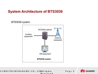
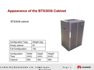
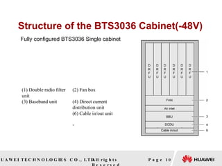
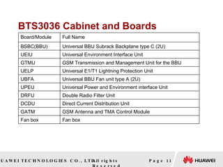
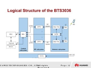
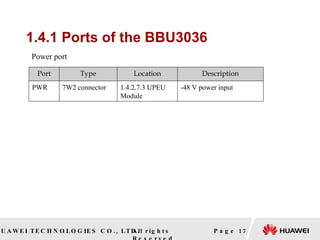
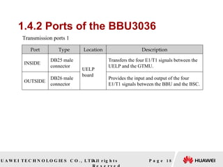
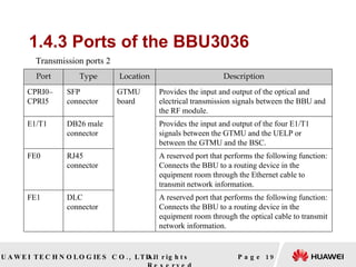
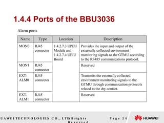
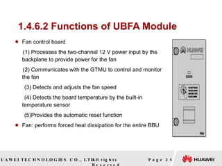
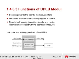
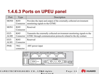
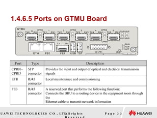
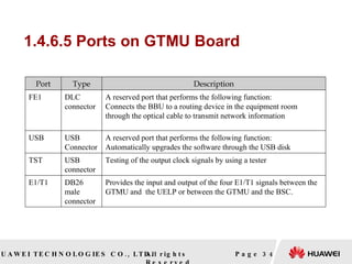
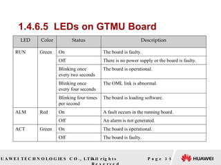
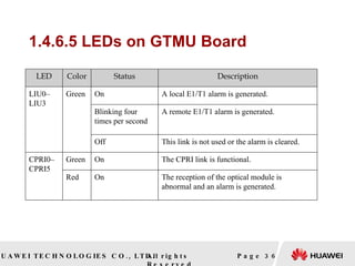
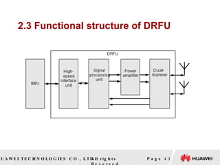
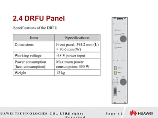
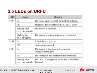
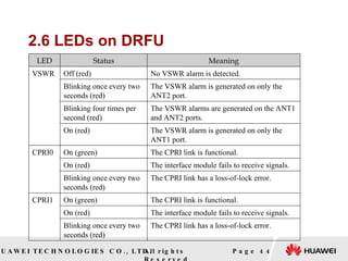
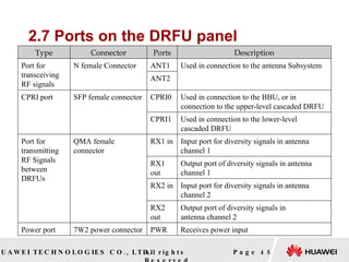
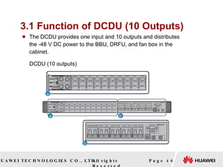
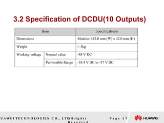
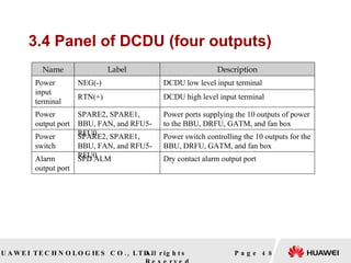


1. The document describes the structure and components of the HUAWEI BTS3036 mobile communication system. It includes a baseband unit (BBU) cabinet, double radio filter unit (DRFU), direct current distribution unit (DCDU), and fan box. 2. The BBU cabinet houses the main boards, including the baseband board, environment interface board, GSM transmission board, and E1/T1 protection board. It also includes interface modules and power/fan modules. 3. The document provides detailed information on the ports, LED indicators, and functions of each component board within the BBU cabinet, including the baseband board, power board, environment interface board, and G


