Download to read offline
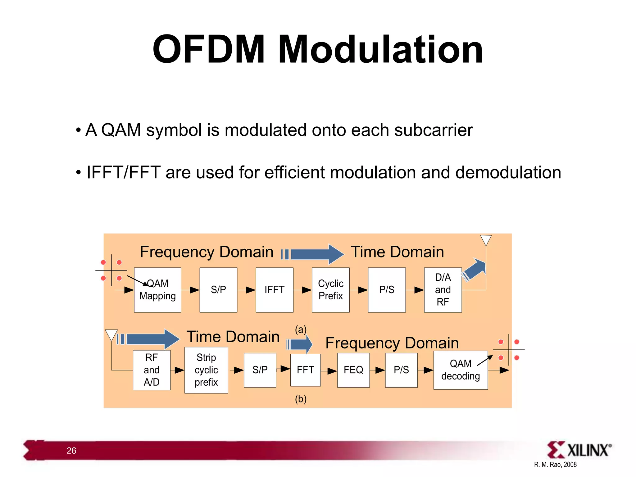
![R. M. Rao, 2008
19
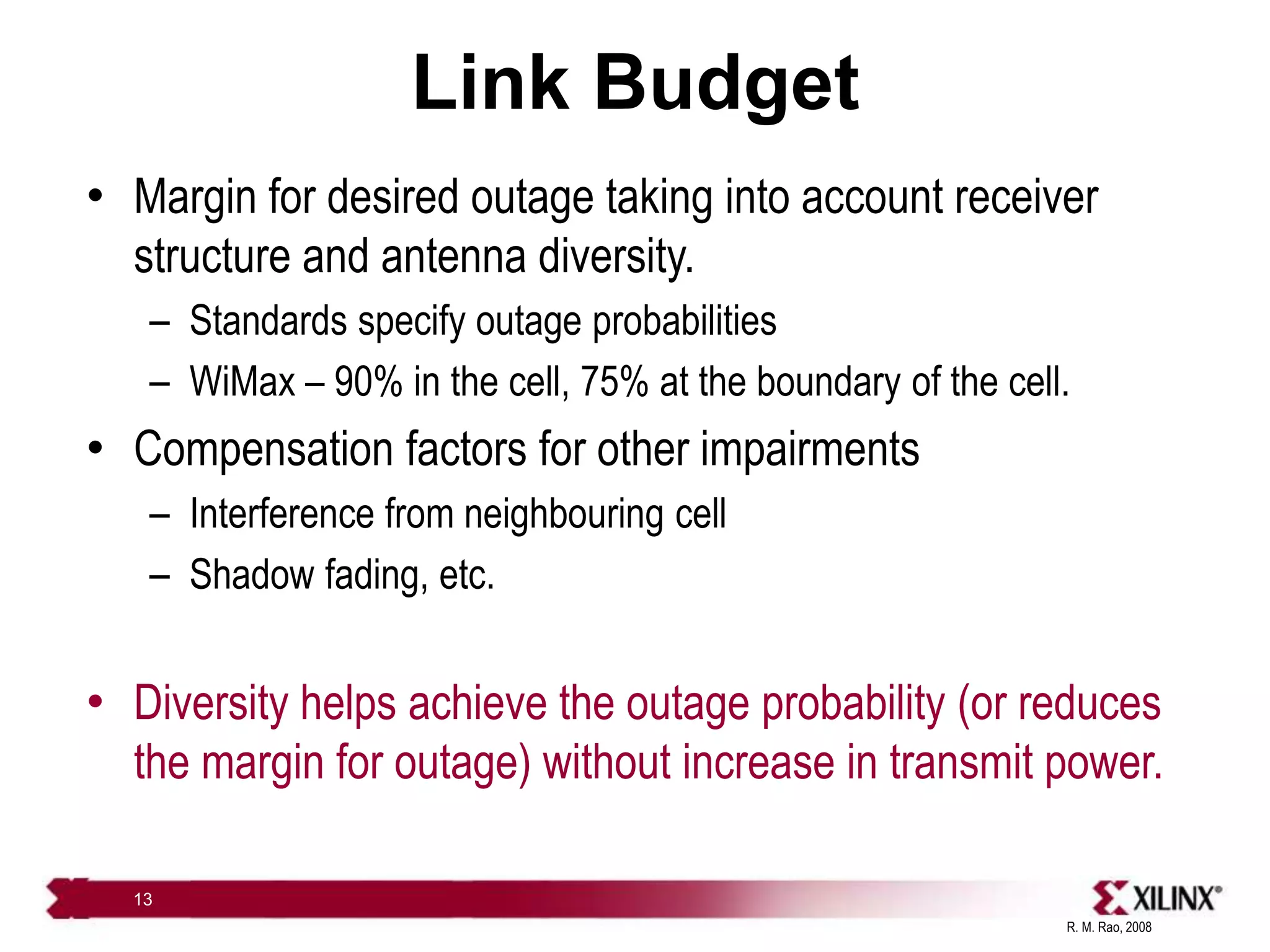
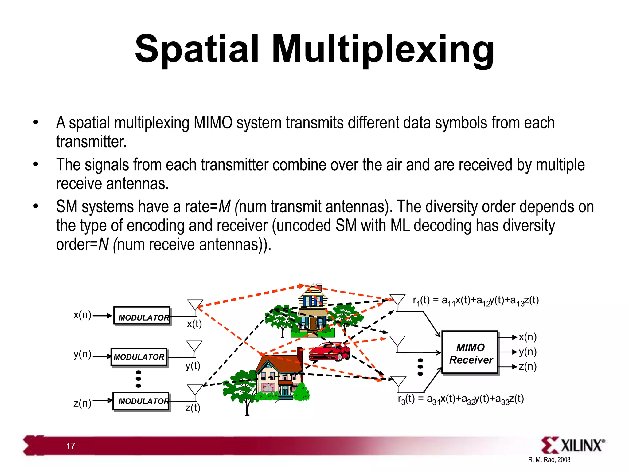
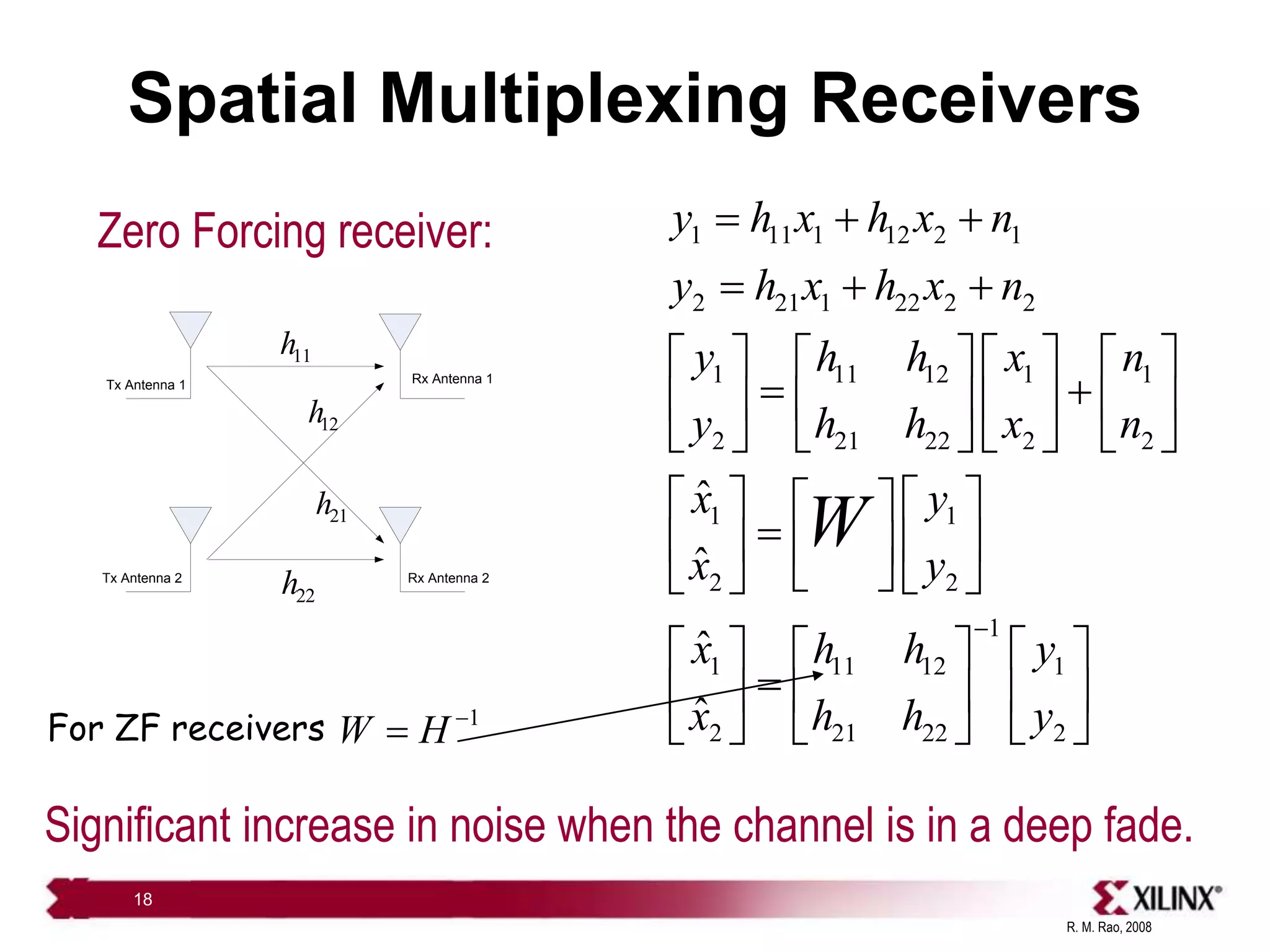
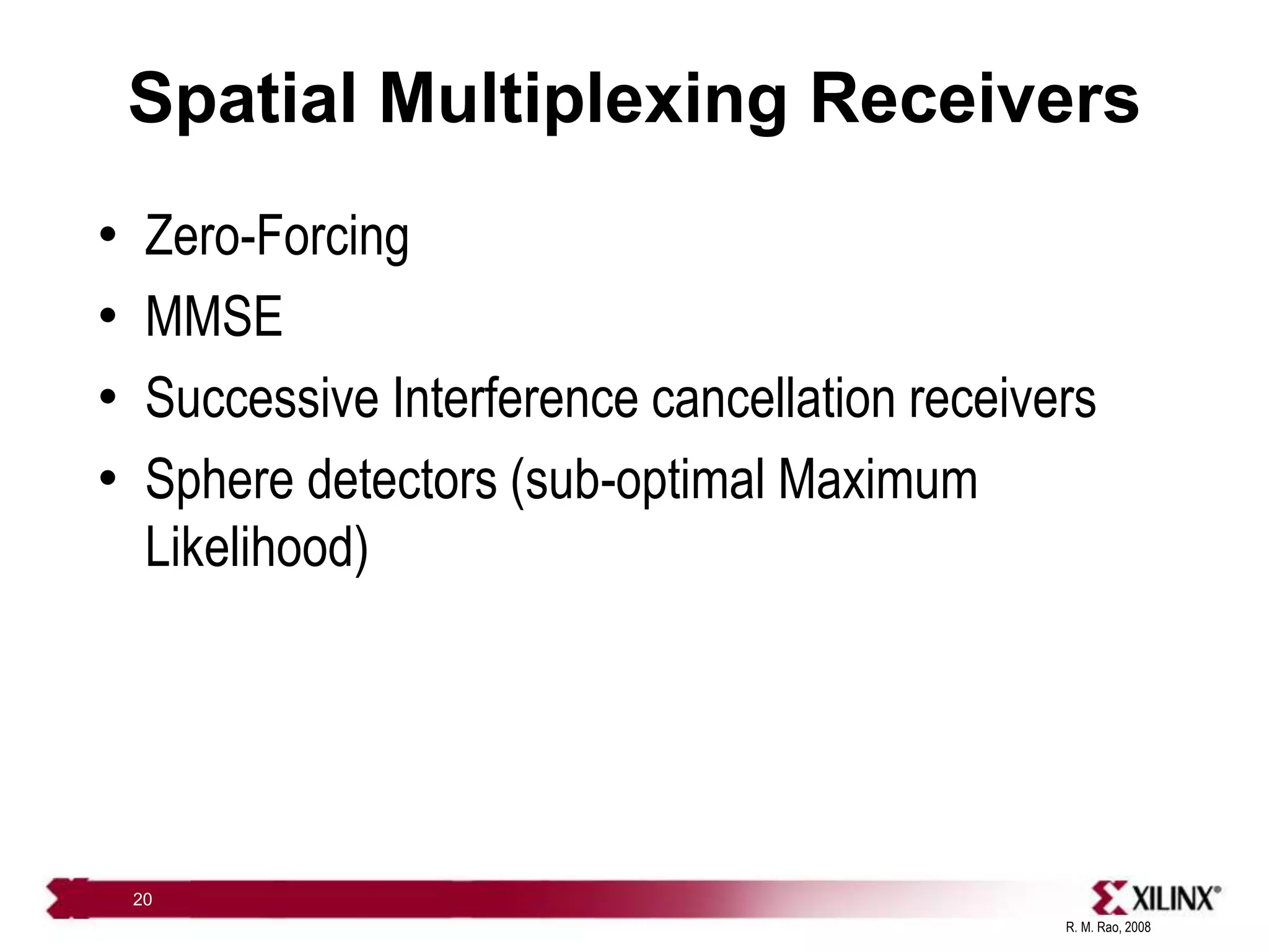
Spatial Multiplexing Receivers
• MMSE MIMO Decoders:
– Cancels interference and minimizes noise.
– Minimizes the over all error (mean squared error).
2
ˆ
[( ) ]
E x x
1
H H
MMSE M
s
M M
W H H I H
E SNR
](https://image.slidesharecdn.com/rao-vlsi-comm-091-230926054923-c2410976/75/rao-vlsi-comm-09-1-ppt-19-2048.jpg)
![R. M. Rao, 2008
73
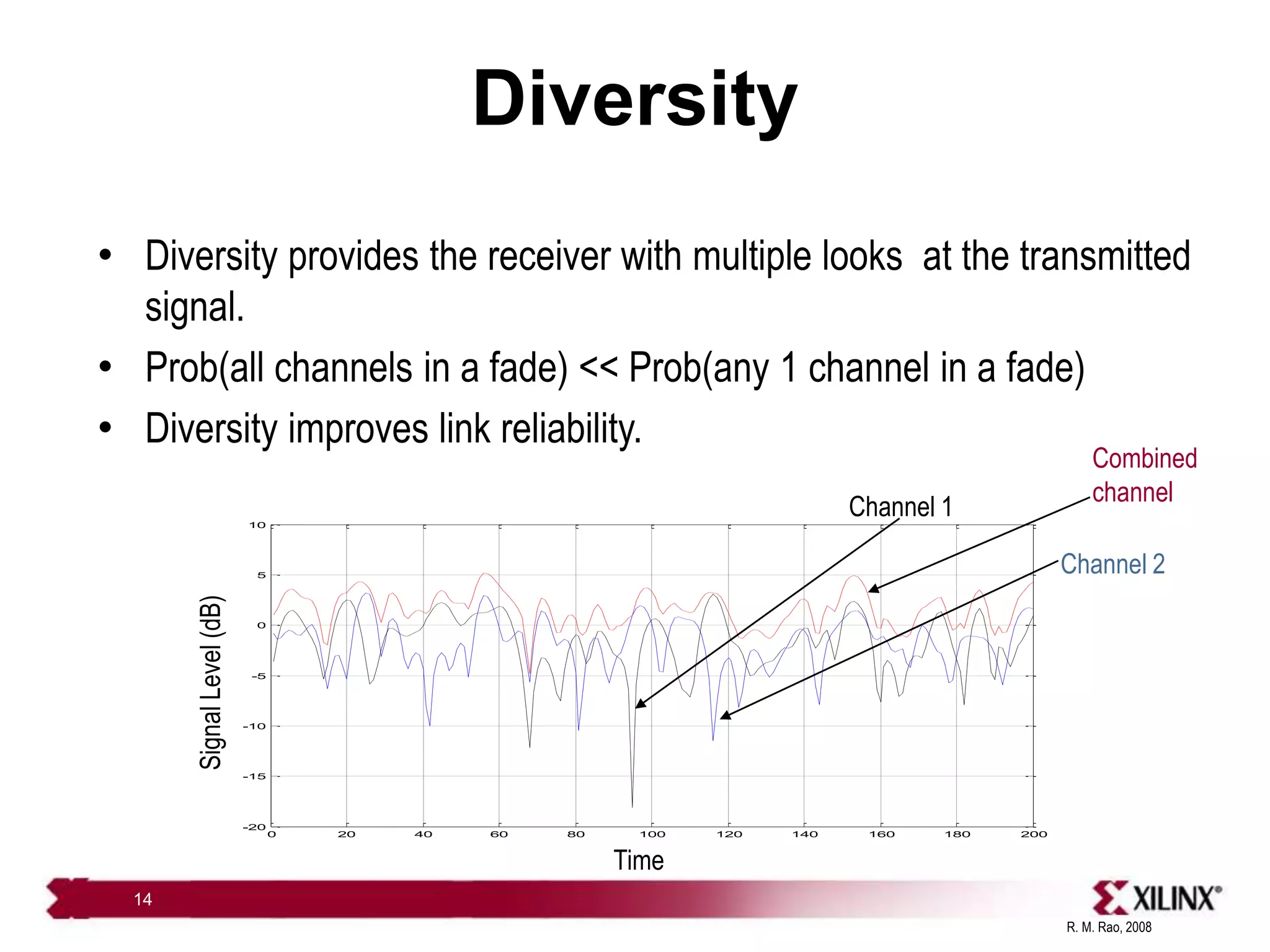
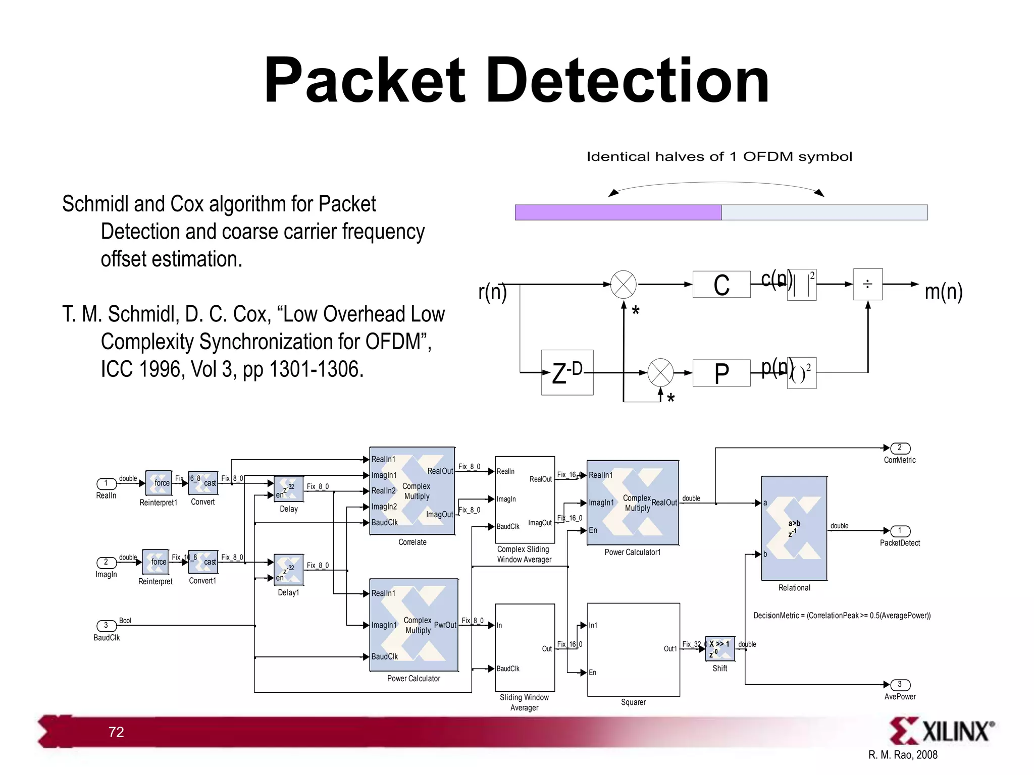
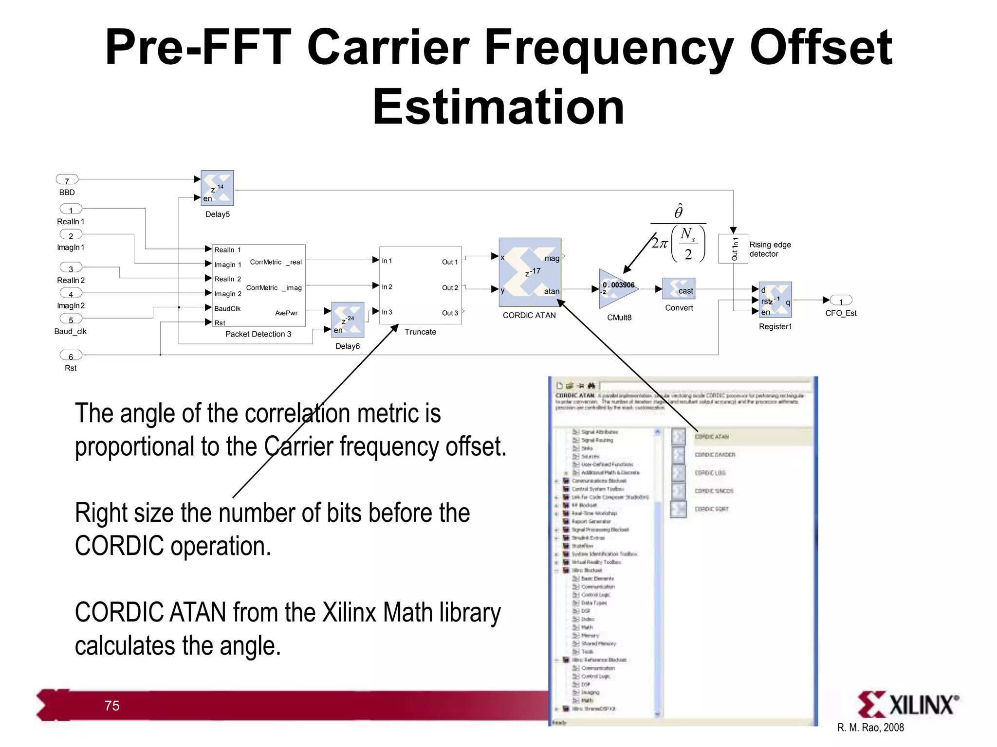
Two Branch CFO estimation using
Schmidl and Cox algo
AvePwr
3
CorrMetric _imag
2
CorrMetric _real
1
Sliding Window
Averager
In
BaudClk
Rst
Out
Slice5
[a:b]
Slice3
[a:b]
Slice2
[a:b]
Slice1
[a:b]
Reinterpret 4
reinterpret
Reinterpret 3
reinterpret
Reinterpret 2
reinterpret
Reinterpret 1
reinterpret
Magnitude -Squared 1
Squarer
RealIn 1
ImagIn 1
RealIn 2
ImagIn 2
BaudClk
RealOut
Delay 4
en
z
-32
Delay 3
en
z
-32
Delay 2
en
z
-2
Delay 1
en
z
-32
Delay
en
z
-32
Complex Sliding
Window Averager 1
RealIn
ImagIn
BaudClk
Rst
RealOut
ImagOut
Complex Sliding
Window Averager
RealIn
ImagIn
BaudClk
Rst
RealOut
ImagOut
Complex Multiply 3
Complex
Multiply
RealIn 1
ImagIn 1
RealIn 2
ImagIn 2
BaudClk
RealOut
ImagOut
Complex Multiply 2
Complex
Multiply
RealIn 1
ImagIn 1
RealIn 2
ImagIn 2
BaudClk
RealOut
ImagOut
AddSub 2
a
b
a + b
z
-1
AddSub 1
a
b
a + b
z
-1
Rst
6
BaudClk
5
ImagIn 2
4
RealIn 2
3
ImagIn 1
2
RealIn 1
1
a
b
Combine the metric
from both Antennas
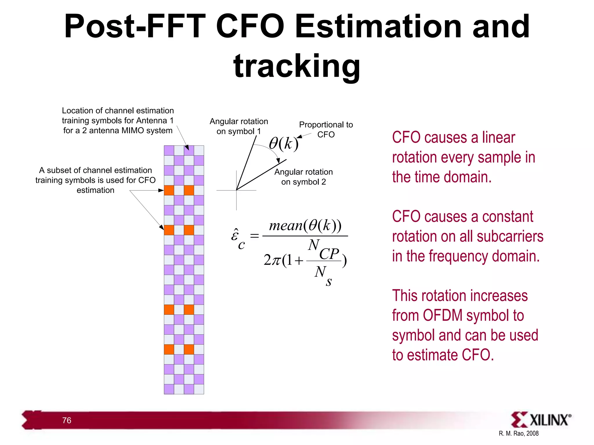
Carrier Frequency Offset causes a linearly increasing rotation in the time domain
j
Ye q
Y](https://image.slidesharecdn.com/rao-vlsi-comm-091-230926054923-c2410976/75/rao-vlsi-comm-09-1-ppt-73-2048.jpg)
![R. M. Rao, 2008
79
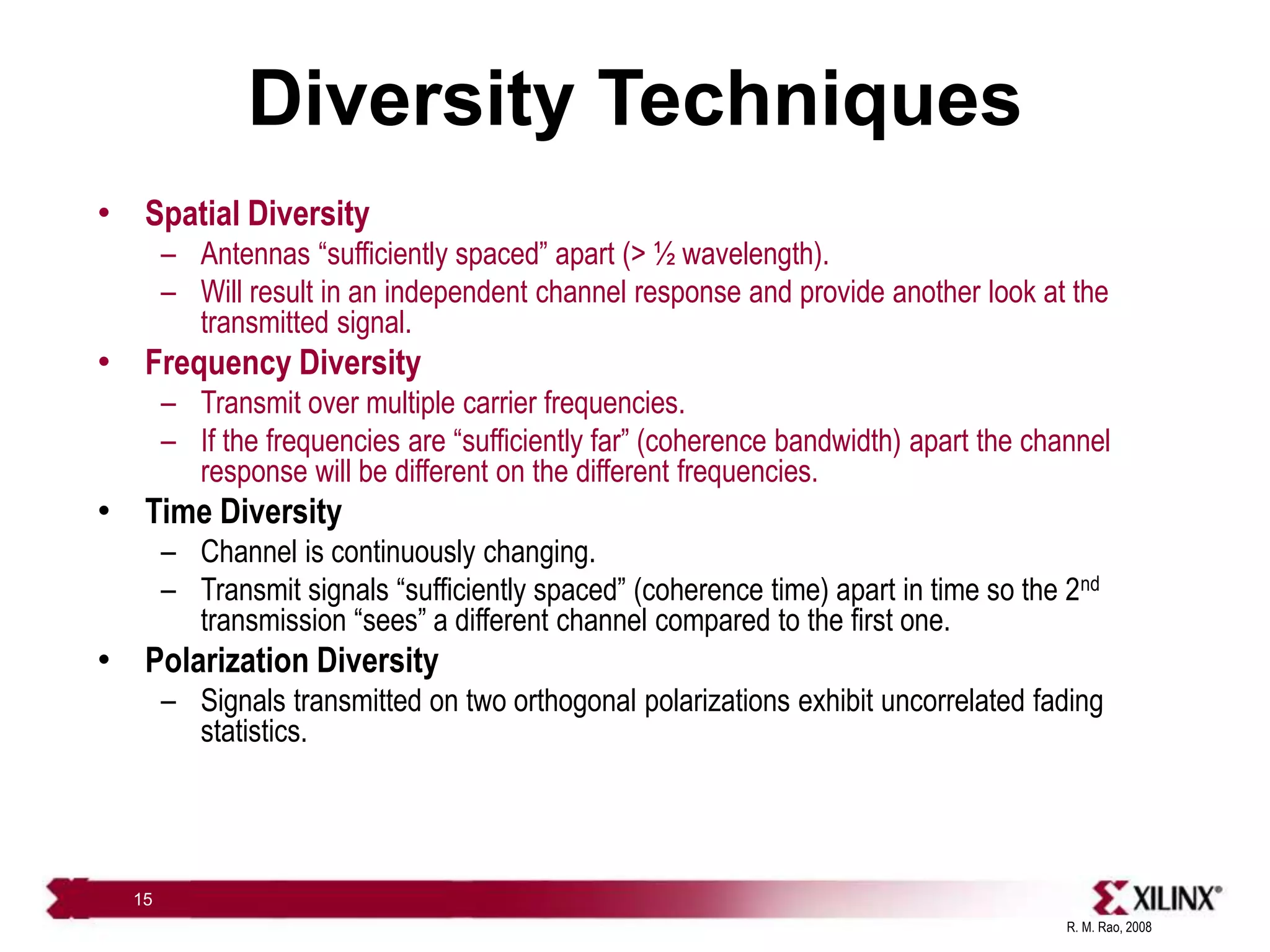
End of Roadmap for the
Von Neumann Model
SPECInt92/MHz
Source: Ronen [2001]
CPUs are as smart as they can be!
MHz
L2 $
Spot the CPU!
L1 $
CPU
Source: Agarwala [2002]
TI 6416
Clock
frequency
scaling
Absolute
power limits
With Moore’s law you
also get leakage!
Source: Borkar [1999]
Divide and
conquer
Source: Zu & Baas [2006]
Multi-core Arrays
1945-2005
Sequential
programming
2005 - ????
Concurrent
programming 6x6 GALS Processor Array](https://image.slidesharecdn.com/rao-vlsi-comm-091-230926054923-c2410976/75/rao-vlsi-comm-09-1-ppt-79-2048.jpg)

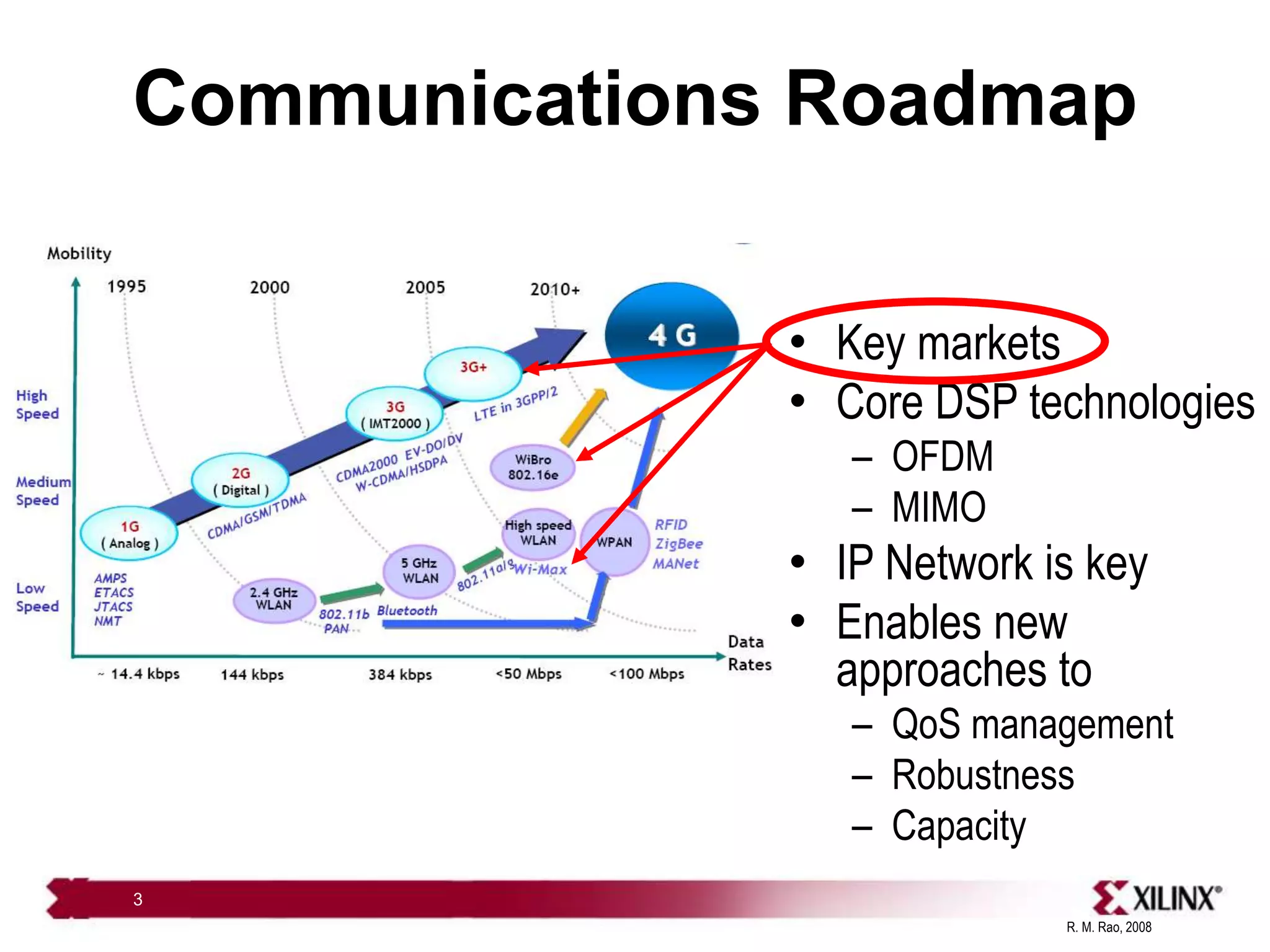
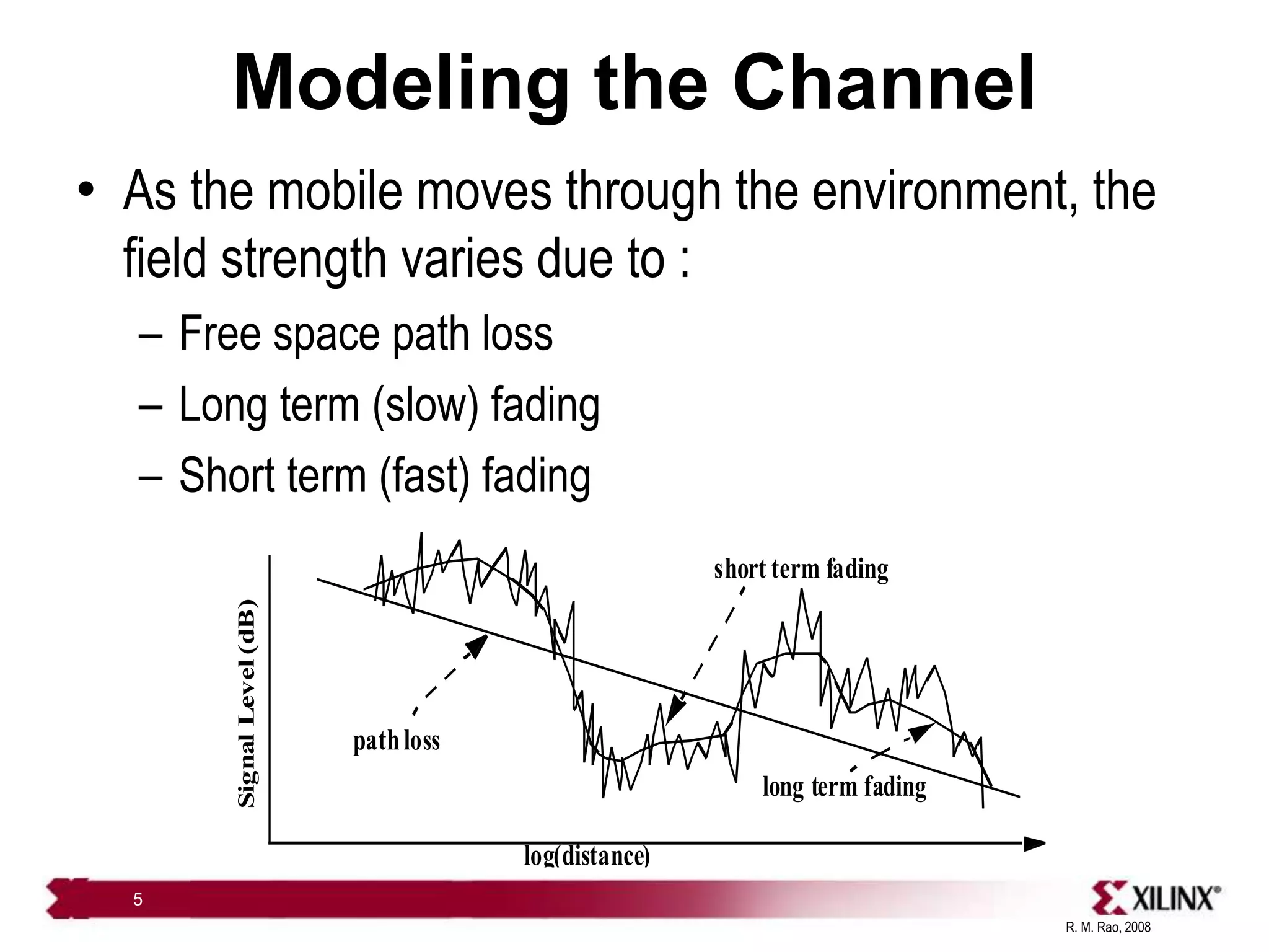
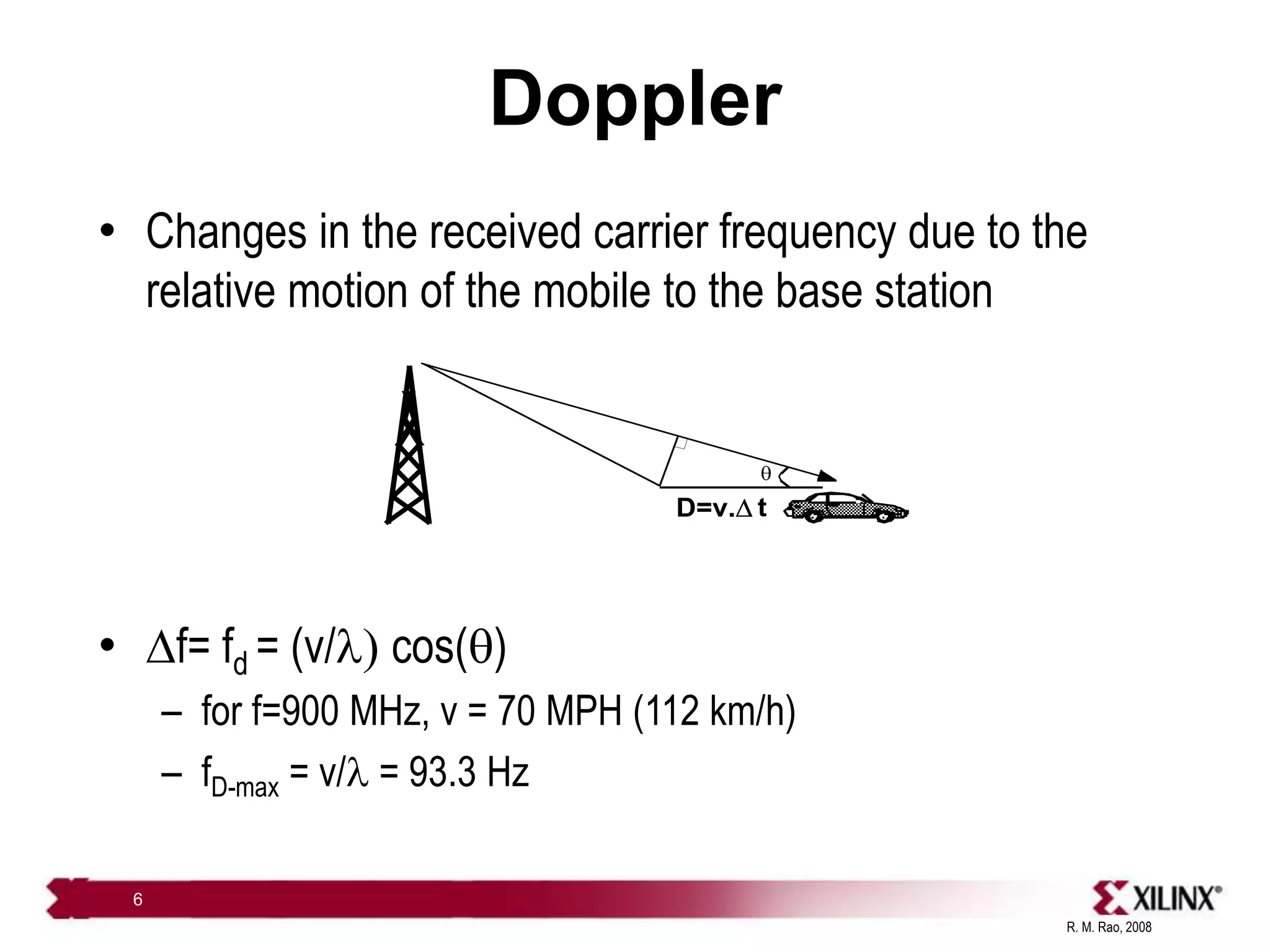
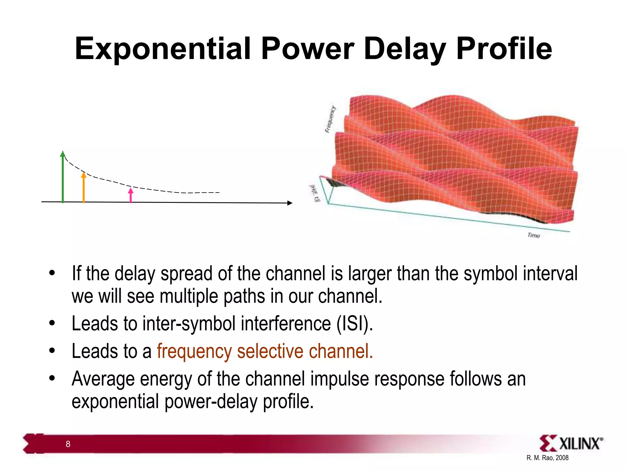
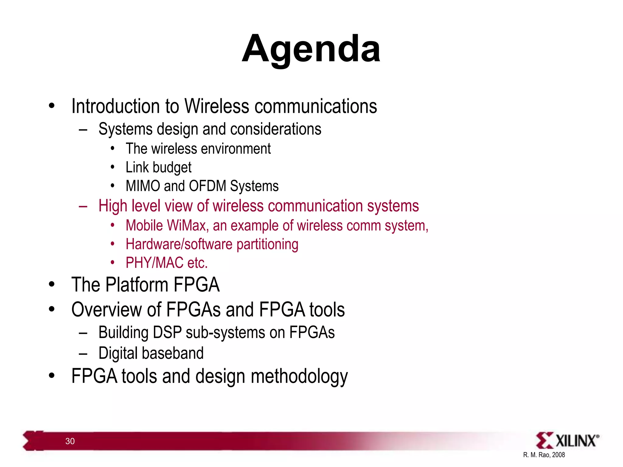
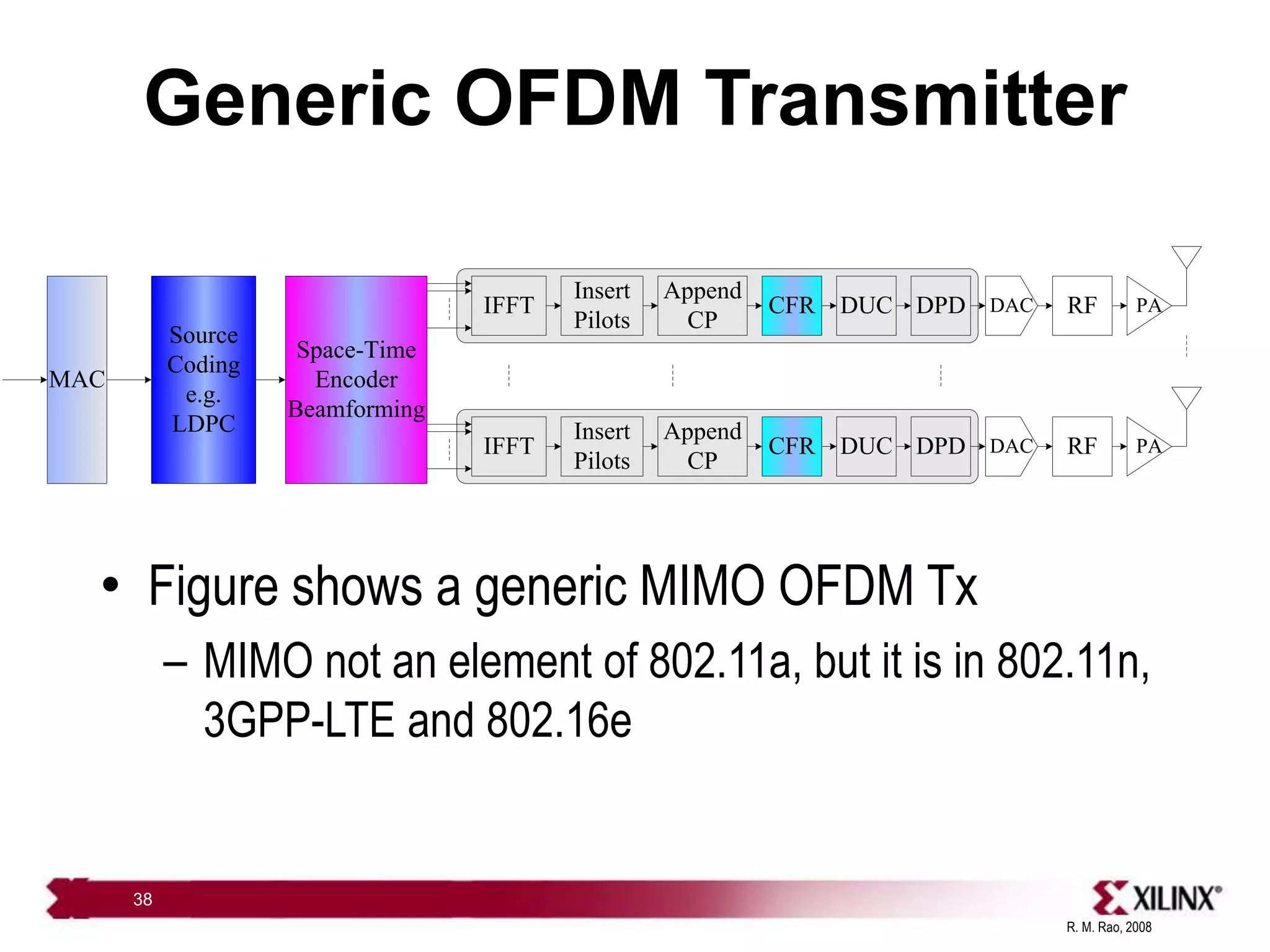
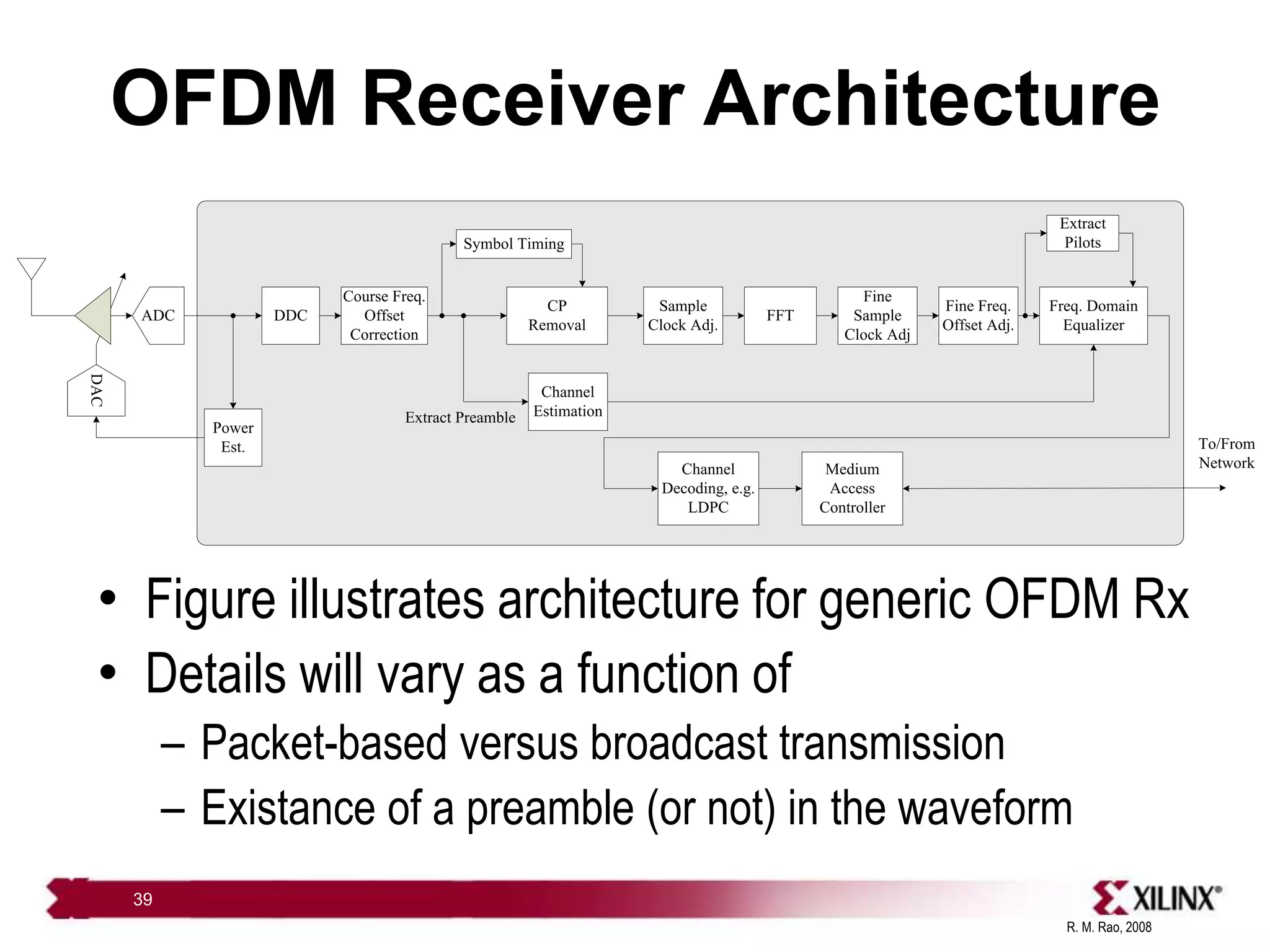
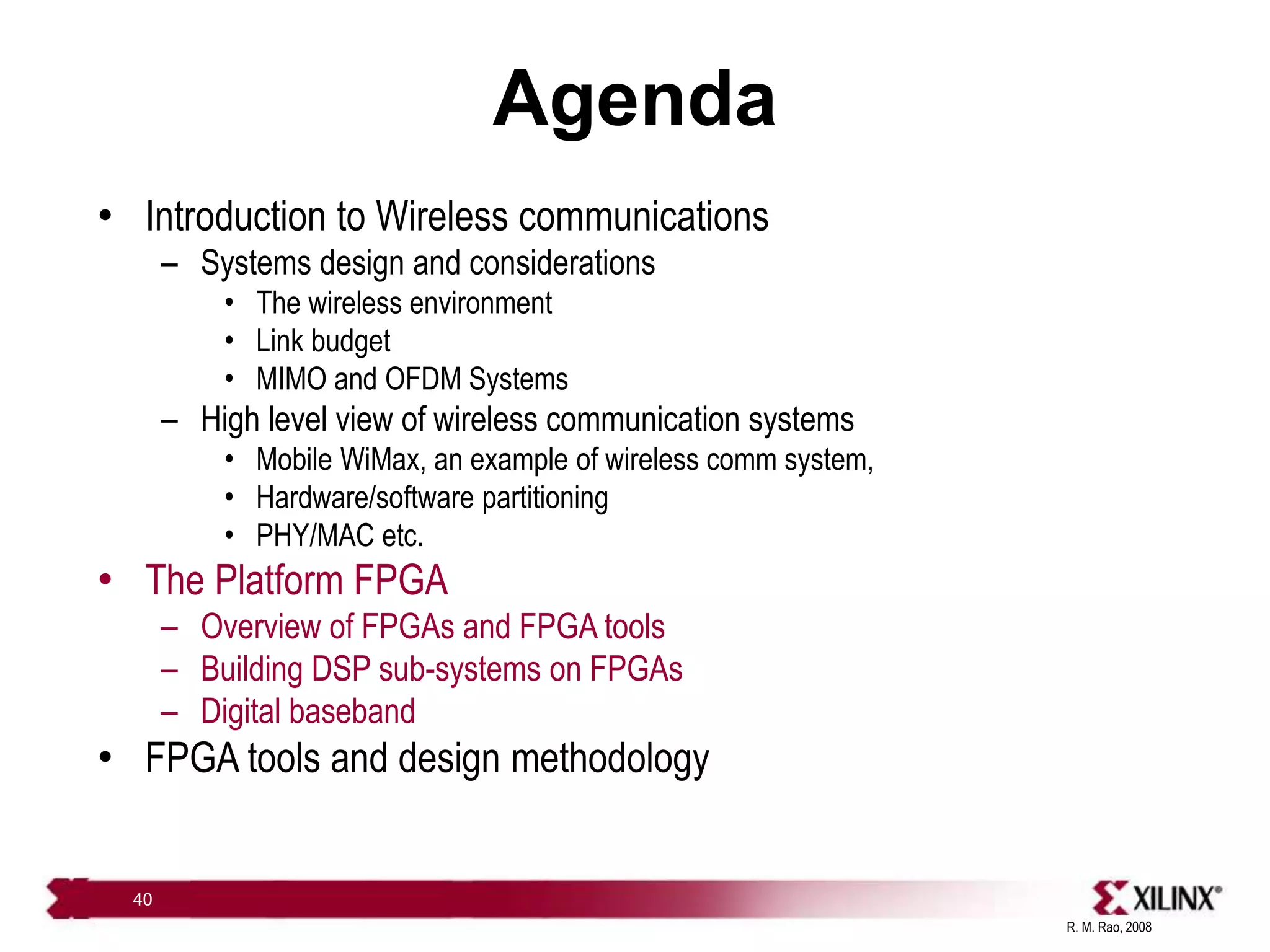
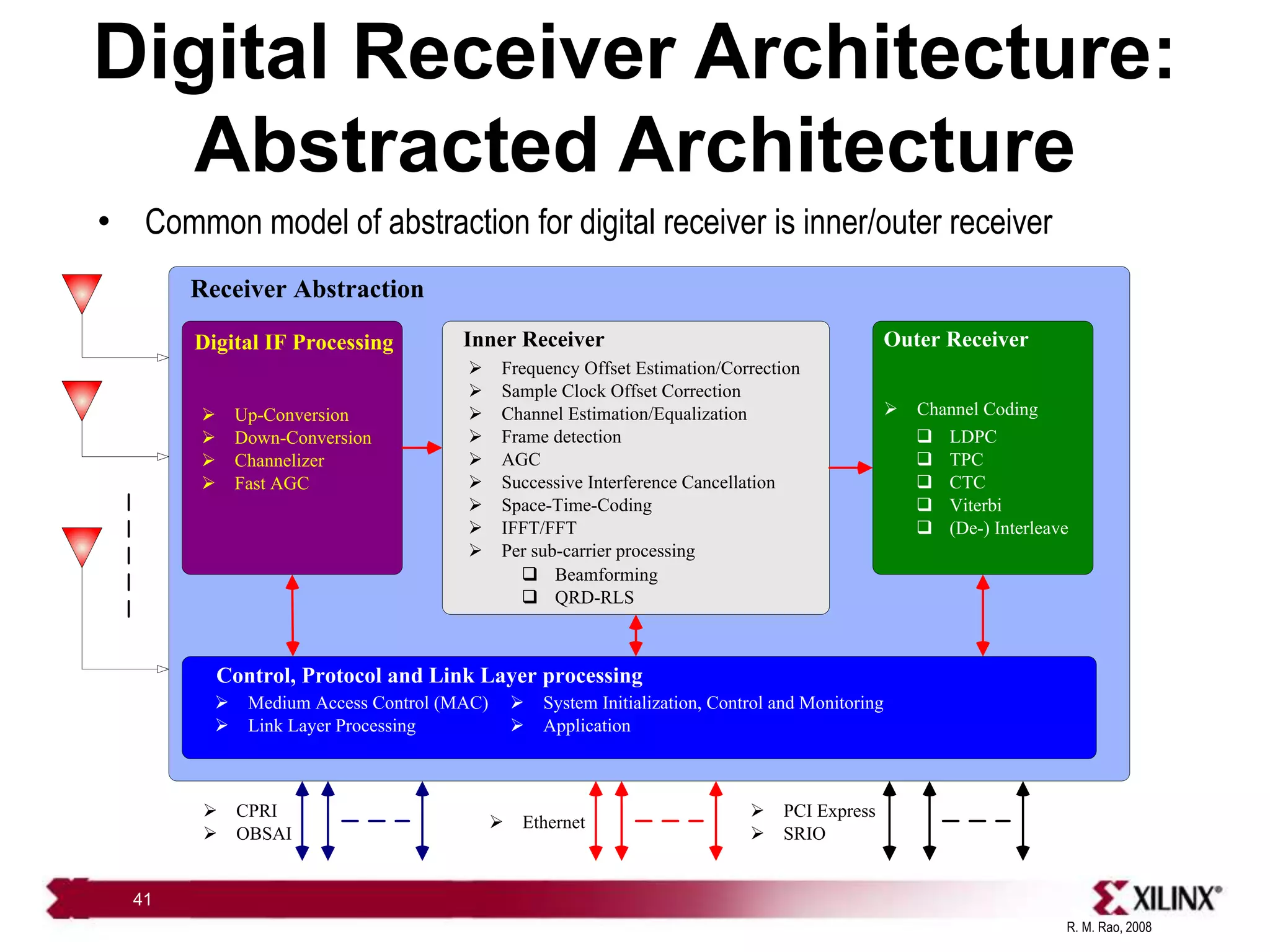
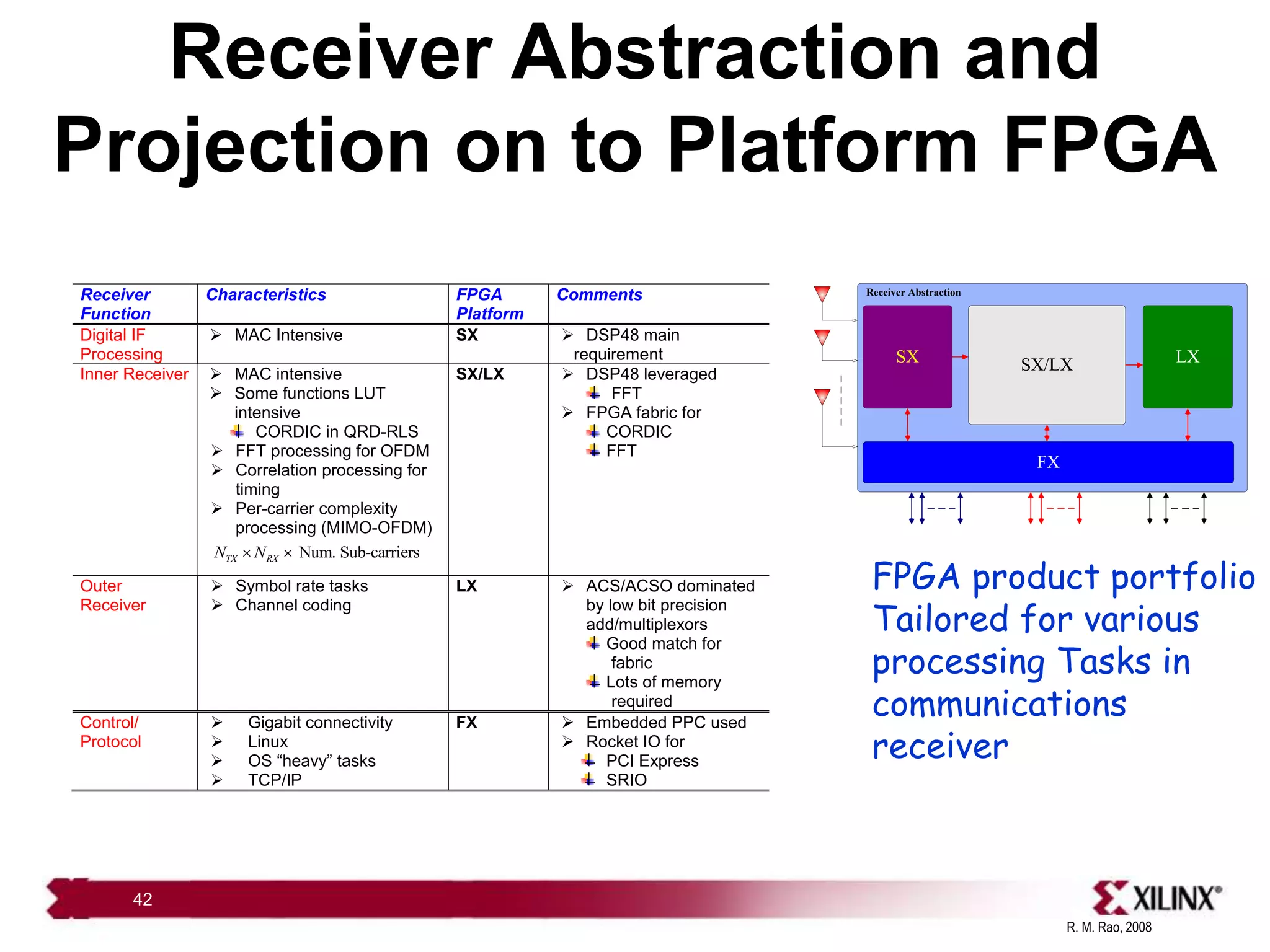
This document provides an overview of wireless communications and mobile WiMax systems. It discusses key topics like the wireless environment, link budgets, MIMO and OFDM techniques, and hardware/software partitioning in wireless systems. It also introduces FPGAs and their role in building DSP subsystems for digital baseband processing in wireless applications. Mobile WiMax is presented as an example wireless communication system that utilizes many of these technologies.


![[Year 2012-13] Mimo technology](https://cdn.slidesharecdn.com/ss_thumbnails/mimotechnology-180701101303-thumbnail.jpg?width=640&height=640&fit=bounds)


![Mimo [new]](https://cdn.slidesharecdn.com/ss_thumbnails/mimonew-150914045107-lva1-app6892-thumbnail.jpg?width=640&height=640&fit=bounds)