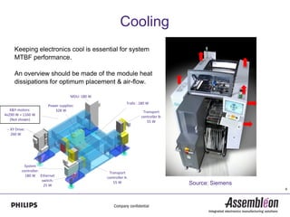
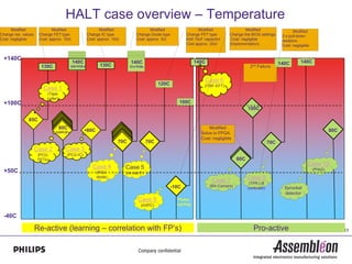
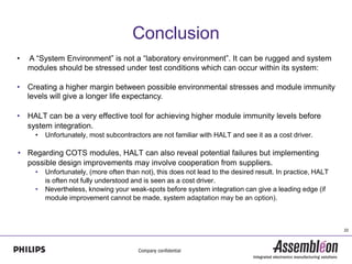
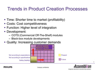
From modular design to System
        Integration
             15 June 2010
        ray.brett@philips.com
Contents
 Trends in Product Creation process
 System reliability
 Module Pro-active evaluation before integration
 System environments
 System environments and module immunity
 Arrhenius law and cooling
 HALT testing and case overview
     Temperature
     Transients (EFT)
 Shock & Vibration
 Conclusion


                                                    2
Trends in Product Creation Processes

   Time: Shorter time to market (profitability)
   Costs: Cost competitiveness
   Function: Higher level of integration
   Development:
     – COTS (Commercial Off-The-Shelf) modules
     – Black-box module developments
 Quality: Increasing customer demands
                                        Customer expects:
                                        Maximum up-time
                                        Maximum performance


     Not according to expectations                            Present
     Not according to specifications
                                                              Future
                   Safety (liability)
                                                                        3
System reliability
“A chain is only as strong as its weakest link" applies to
any process that will fail if some step in it goes wrong.

Problem:
How to ensure that the system will perform as intended
and will work reliably throughout it’s (intended) lifecycle -
after various modules have been integrated?


                                                                4
Module Pro-active evaluation before integration


ModuleTesting involves checking that the module performs
according to its specifications.
However, before system integration, extra environmental
stress-testing (such as HALT) can ensure that they will
function reliably in their intended system environment.


                                                           5
System Environment
A “System Environment” is not a “laboratory environment”. Instead, it is
usually rugged and modules can be exposed to various phenomena such as:


   – Heat : 35C environment temperature can be common in some geographical areas and
     can cause much higher temperatures in modules behind covers.
   – Shock & Vibration – depending on the machine type but also take into account transport
     and installation (dropping/bumping).
   – Electromagnetic noise (intra machine compatibility)

   –   Other phenomena includes:
   –   Pluggable “Module hot swapping” (this can be common)
   –   Inrush currents
   –   Grounding
   –   Crosstalk
   –   EMC and Safety (Regulatory requirements)
   –   Other                                                                                  6
System Environment & module immunity
 The system architecture should be designed such that its environment
  is kept as “friendly” as possible as far as electronics is concerned.
    – This involves:
       • Cooling considerations                                          Increase
                                                                         Design
       • Reduction of mechanical stresses                                Margin


       • Reduction of electromagnetic phenomena
           – Inrush; ESD; Crosstalk etc.
                                                    System environment              Module immunity


 Modules should be designed/selected so that they can withstand the
  harsh environments in which they can be exposed.

 This can create a margin between possible environmental stresses and
  higher module immunity levels, giving longer life expectancy.

                                                                                                      7
Arrhenius law in lifetime acceleration for electronics

                                         Tacc =exp[(Ea/k)*(1/Ta - 1/T)]
                                             Thermal acceleration of failure rate
                    1.0E-01

                                                                      Factor 811

                                                              Factor 452
                    1.0E-02
                                                         Factor 244
    Reaction rate


                                                     Factor 127


                    1.0E-03
                                         Factor 31


                              Factor 6                                                                   Ea = 0.72
                    1.0E-04
                                                                                         K = Boltzmann’s constant
                        Factor 2,6
                                                                                                       T = Kelvin


                    1.0E-05
                                 20         40           60           80           100   120       140         160

                                                                  Temperature oC                                     8
Cooling
      Keeping electronics cool is essential for system
      MTBF performance.

      An overview should be made of the module heat
      dissipations for optimum placement & air-flow.

                                      MDU: 180 W
                                                               Trafo : 180 W
                         Power supplies:
   X&Y-motors:              328 W                                       Transport
4x290 W = 1160 W                                                       controller B:
   (Not shown)                                                            55 W
 -- XY Drive:
    260 W


           System
          controller:                               Transport
            180 W Ethernet                         controller A:
                      switch:                         55 W
                       25 W                                                            Source: Siemens
                                                                                                         9
HALT

 “A chain is only as strong as its weakest link" applies to any process
  that will fail if some step in it goes wrong.

 HALT (High Accelerated Life Testing) can be useful in identifying such
  "weak links" before system integration/Total Test. Consequently design
  margins can be increased to improve system reliability.


                                                                           10
What is HALT ?
 HALT is an engineering step-stress-to-fail process which can reveal
  design flaws quickly (within hours of testing).
 HALT is not a compliance test and not limited by component or product
  specifications.
                                         Failure
                                                   Evaluate the relevance of the failure.
                                                   Determine if stress-level is acceptible and
                                                   implement corrective action if necessary.


                           Failure


  Specification (max.)
                                         Evaluate the relevance of the failure.
                                         Determine if stress-level is acceptible and
                                         implement corrective action if necessary.
   Increase stress

Apply stress
                                                                                                 11
 (10-15min)
HALT tests may include:

 Temperature
   • (-40oC to 140oC) under max. loading conditions
   • In combination with power cycling (ON/OFF)
 Temperature cycling
 Voltage (in combination with temp.)
 Electric transient susceptibility (all cables)
 Shock & vibration
 RH%


                                                      12
HALT case overview – Temperature
      Modified               Modified                        Modified                   Modified                  Modified                 Modified                     Modified
Change res. values    Change FET type                 Change IC type            Change Diode type           Change FET type       Change the BIOS settings.      2 x pull-down
Cost: negligible      Cost: approx. 10ct              Cost: approx. 10ct        Cost: approx. 5ct           Add 10uF capacitor     Cost: negligible              resistors.
                                                                                                            Cost approx. 20ct     (Implementation)               Cost: negligible


  +140C
                                           140C                              140C                                140C                                           140C        140C
                       130C               X20 PCB’s          130C            X14 PCBs                                                        2nd Failure


                                                                                                                      Case 6
                                                                                              120C                   (ITBF-EFT)
                        Case 1
                          (Tape
                          cutter)
  +100C                                                                                                 100C
                                                                                                                                            100C

               85C
                                    80C                                                                                Modified
                               X20PCB’s               80C                                                                                                                                    80C
                                                                                                                   Solve in FPGA
                                                                                                                   Cost: negligible
                                                                       70C              70C                                                               70C
                     Case 2           Case 3
                      (PCU-           (PCU-IC)
                      FETs)                                                                                                           60C
                                                         Case 4                                                                                                                 Case 10
                                                                           Case 5                                                                                                   (PHs2)
  +50C                                                      (PCU-          (re-use F)
                                                            diode)
                                                                                                                         Case 7             Case 9
                                                                                                                                             (TPR Lift
                                                                                                     -10C               (BA-Camera)
                                                                                                                                            controller)           Sprocket
                                                                                                                                                                  detector
                                                                                 Case 8                Power
                                                                                   (AXPC)              cycling


  -40C

                     Re-active (learning – correlation with FP’s)                                                                              Pro-active                                          13
Summary: Performing Temperature HALT

 For HALT; (Rule of Thumb): ensure a margin of at least 40C above
  specification.
    • (This is NOT a continuous spec!)

 It’s important to analyze all failures and to decide on:
    • Root cause
    • Evaluate the relevance of the failure
    • What is the effort/cost for improvement


                                                                     14
Electric transients (EFT)


 Electronic circuits with cable connections are prone to electric transients.

 Cables can be excellent antenna’s, depending on impedances, length etc. and can
 pick up such transients:

 This phenomenon deals with intra-EMC immunity, NOT EMC-Directive
                                                                                    15
Example of an electric transient and effects

                                         Relay switching off a load with
                                         a residue voltage.


                                                         Possible resultant damage caused by
  Possible resultant transient voltage                   a transient voltage disturbance.
  which can be induced into nearby
  cables or locally on a PCB.
                                                                                               16
HALT case overview – Transients (EFT)
    Modified                    Modified                 Modified                 Modified                  Modified       Design integration
Add 10nF cap.               Gnd. connection         Add 2x10nF caps.         Shield repeater           Gnd. connection     EMC
Cost: negligible            Cost: negligible        Cost: negligible         Cost: 5 euro              Cost: 10ct          Cost: negligible
10kV
                    10kV                        10kV                       10kV
                                                                                                                                                                Case 8
9kV                                                                                                                                                                  (TPR)


                                 At approx. 8kV,                                                                                                                        8kV
8kV
                            Cable isolation gets “tricky”                                      8kV
                                                                                              defect
                                                                                                                                                Design integration
7kV                                                                                                                                             EMC
                                                                                                                                                Cost: negligible
                                                                                                                         6kV
6kV                                                                                                                                Case 6
                                                                                                                                     (BA-
                                                                                                                                    Camera)
5kV
                                                            Case 3                Case 4                                                                 Case 7
                                                           (Tape cutter)          Fire-Wire                                                              (LED pcb)
                                                             mP reset             Repeater
4kV                                                                                                                                 4kV


3kV          3kV                          3kV                                                               Case 5                                        2.8kV
                                                                                       2.5kV                (Sprocket
                                                                                                             detector)
2kV                Case 1                                          2kV
                                                Case 2
                 3kV                            2kV
                                                 (ITBF)                                   1.5kV
                                                mP reset                                  defect                1kV
1kV           FET defect
                                                                              0.5kV                                                                 0.6kV


             Re-active (learning – correlation with FP’s)                                                                        Pro-active                                   17
Transient “Rule of thumb” HALT targets

   “Hard failure” (>4kV)
      • A Hard failure can be either a H/W defect or a catastrophic S/W error.
      • A catastrophic S/W error could involve restarting an application after a
        “freeze-up”.
      • A H/W defect could involve a defect component.

   “Soft” error: (>2kV)
      • A soft error usually involves a software failure but may not affect the
        system in any serious manner.
          – E.g. a sub-system/system “hiccup” which is self recoverable.
              – A certain amount of immunity is needed because too many “hiccups”
                 may affect machine throughput.


                                                                                    18
System environment (Shock & Vibration)

 The relationship between shock & vibration and module lifetime.

   – Example: Servo controls placed on robot placement heads
   – Up to now we have custom-made products where we apply
     stringent shock & vibration requirements.


                                                                    19
Shock & Vibration
 Early involvement of the behaviour of the electrical, mechanical
  and optical BA Fumo design during shock and vibration.

 Trace the problems before re-design

 Focus on
   – reliability of electrical boards and connections
   – reliability optical mountings
   – reliability of mechanical attachements

 During operation and transport


                                                                     20
Example


  PHSx-O
  Representing Optics                                                  PHSx-E
                                                                       Representing Electronics


For HALT; (Rule of Thumb): ensure a margin of at least a factor of 2 above spec.                 21
Conclusion
•   A “System Environment” is not a “laboratory environment”. It can be rugged and system
    modules should be stressed under test conditions which can occur within its system:

•   Creating a higher margin between possible environmental stresses and module immunity
    levels will give a longer life expectancy.

•   HALT can be a very effective tool for achieving higher module immunity levels before
    system integration.
      •   Unfortunately, most subcontractors are not familiar with HALT and see it as a cost driver.

• Regarding COTS modules, HALT can also reveal potential failures but implementing
  possible design improvements may involve cooperation from suppliers.
      •   Unfortunately, (more often than not), this does not lead to the desired result. In practice, HALT
          is often not fully understood and is seen as a cost driver.
      •   Nevertheless, knowing your weak-spots before system integration can give a leading edge (if
          module improvement cannot be made, system adaptation may be an option).


                                                                                                              22
Questions


            23

13.20 Ray Brett

  • 1.
    From modular designto System Integration 15 June 2010 ray.brett@philips.com
  • 2.
    Contents  Trends inProduct Creation process  System reliability  Module Pro-active evaluation before integration  System environments  System environments and module immunity  Arrhenius law and cooling  HALT testing and case overview  Temperature  Transients (EFT)  Shock & Vibration  Conclusion 2
  • 3.
    Trends in ProductCreation Processes  Time: Shorter time to market (profitability)  Costs: Cost competitiveness  Function: Higher level of integration  Development: – COTS (Commercial Off-The-Shelf) modules – Black-box module developments  Quality: Increasing customer demands Customer expects: Maximum up-time Maximum performance Not according to expectations Present Not according to specifications Future Safety (liability) 3
  • 4.
    System reliability “A chainis only as strong as its weakest link" applies to any process that will fail if some step in it goes wrong. Problem: How to ensure that the system will perform as intended and will work reliably throughout it’s (intended) lifecycle - after various modules have been integrated? 4
  • 5.
    Module Pro-active evaluationbefore integration ModuleTesting involves checking that the module performs according to its specifications. However, before system integration, extra environmental stress-testing (such as HALT) can ensure that they will function reliably in their intended system environment. 5
  • 6.
    System Environment A “SystemEnvironment” is not a “laboratory environment”. Instead, it is usually rugged and modules can be exposed to various phenomena such as: – Heat : 35C environment temperature can be common in some geographical areas and can cause much higher temperatures in modules behind covers. – Shock & Vibration – depending on the machine type but also take into account transport and installation (dropping/bumping). – Electromagnetic noise (intra machine compatibility) – Other phenomena includes: – Pluggable “Module hot swapping” (this can be common) – Inrush currents – Grounding – Crosstalk – EMC and Safety (Regulatory requirements) – Other 6
  • 7.
    System Environment &module immunity  The system architecture should be designed such that its environment is kept as “friendly” as possible as far as electronics is concerned. – This involves: • Cooling considerations Increase Design • Reduction of mechanical stresses Margin • Reduction of electromagnetic phenomena – Inrush; ESD; Crosstalk etc. System environment Module immunity  Modules should be designed/selected so that they can withstand the harsh environments in which they can be exposed.  This can create a margin between possible environmental stresses and higher module immunity levels, giving longer life expectancy. 7
  • 8.
    Arrhenius law inlifetime acceleration for electronics Tacc =exp[(Ea/k)*(1/Ta - 1/T)] Thermal acceleration of failure rate 1.0E-01 Factor 811 Factor 452 1.0E-02 Factor 244 Reaction rate Factor 127 1.0E-03 Factor 31 Factor 6 Ea = 0.72 1.0E-04 K = Boltzmann’s constant Factor 2,6 T = Kelvin 1.0E-05 20 40 60 80 100 120 140 160 Temperature oC 8
  • 9.
    Cooling Keeping electronics cool is essential for system MTBF performance. An overview should be made of the module heat dissipations for optimum placement & air-flow. MDU: 180 W Trafo : 180 W Power supplies: X&Y-motors: 328 W Transport 4x290 W = 1160 W controller B: (Not shown) 55 W -- XY Drive: 260 W System controller: Transport 180 W Ethernet controller A: switch: 55 W 25 W Source: Siemens 9
  • 10.
    HALT  “A chainis only as strong as its weakest link" applies to any process that will fail if some step in it goes wrong.  HALT (High Accelerated Life Testing) can be useful in identifying such "weak links" before system integration/Total Test. Consequently design margins can be increased to improve system reliability. 10
  • 11.
    What is HALT?  HALT is an engineering step-stress-to-fail process which can reveal design flaws quickly (within hours of testing).  HALT is not a compliance test and not limited by component or product specifications. Failure Evaluate the relevance of the failure. Determine if stress-level is acceptible and implement corrective action if necessary. Failure Specification (max.) Evaluate the relevance of the failure. Determine if stress-level is acceptible and implement corrective action if necessary. Increase stress Apply stress 11 (10-15min)
  • 12.
    HALT tests mayinclude:  Temperature • (-40oC to 140oC) under max. loading conditions • In combination with power cycling (ON/OFF)  Temperature cycling  Voltage (in combination with temp.)  Electric transient susceptibility (all cables)  Shock & vibration  RH% 12
  • 13.
    HALT case overview– Temperature Modified Modified Modified Modified Modified Modified Modified Change res. values Change FET type Change IC type Change Diode type Change FET type Change the BIOS settings. 2 x pull-down Cost: negligible Cost: approx. 10ct Cost: approx. 10ct Cost: approx. 5ct Add 10uF capacitor Cost: negligible resistors. Cost approx. 20ct (Implementation) Cost: negligible +140C 140C 140C 140C 140C 140C 130C X20 PCB’s 130C X14 PCBs 2nd Failure Case 6 120C (ITBF-EFT) Case 1 (Tape cutter) +100C 100C 100C 85C 80C Modified X20PCB’s 80C 80C Solve in FPGA Cost: negligible 70C 70C 70C Case 2 Case 3 (PCU- (PCU-IC) FETs) 60C Case 4 Case 10 Case 5 (PHs2) +50C (PCU- (re-use F) diode) Case 7 Case 9 (TPR Lift -10C (BA-Camera) controller) Sprocket detector Case 8 Power (AXPC) cycling -40C Re-active (learning – correlation with FP’s) Pro-active 13
  • 14.
    Summary: Performing TemperatureHALT  For HALT; (Rule of Thumb): ensure a margin of at least 40C above specification. • (This is NOT a continuous spec!)  It’s important to analyze all failures and to decide on: • Root cause • Evaluate the relevance of the failure • What is the effort/cost for improvement 14
  • 15.
    Electric transients (EFT) Electronic circuits with cable connections are prone to electric transients.  Cables can be excellent antenna’s, depending on impedances, length etc. and can pick up such transients:  This phenomenon deals with intra-EMC immunity, NOT EMC-Directive 15
  • 16.
    Example of anelectric transient and effects Relay switching off a load with a residue voltage. Possible resultant damage caused by Possible resultant transient voltage a transient voltage disturbance. which can be induced into nearby cables or locally on a PCB. 16
  • 17.
    HALT case overview– Transients (EFT) Modified Modified Modified Modified Modified Design integration Add 10nF cap. Gnd. connection Add 2x10nF caps. Shield repeater Gnd. connection EMC Cost: negligible Cost: negligible Cost: negligible Cost: 5 euro Cost: 10ct Cost: negligible 10kV 10kV 10kV 10kV Case 8 9kV (TPR) At approx. 8kV, 8kV 8kV Cable isolation gets “tricky” 8kV defect Design integration 7kV EMC Cost: negligible 6kV 6kV Case 6 (BA- Camera) 5kV Case 3 Case 4 Case 7 (Tape cutter) Fire-Wire (LED pcb) mP reset Repeater 4kV 4kV 3kV 3kV 3kV Case 5 2.8kV 2.5kV (Sprocket detector) 2kV Case 1 2kV Case 2 3kV 2kV (ITBF) 1.5kV mP reset defect 1kV 1kV FET defect 0.5kV 0.6kV Re-active (learning – correlation with FP’s) Pro-active 17
  • 18.
    Transient “Rule ofthumb” HALT targets  “Hard failure” (>4kV) • A Hard failure can be either a H/W defect or a catastrophic S/W error. • A catastrophic S/W error could involve restarting an application after a “freeze-up”. • A H/W defect could involve a defect component.  “Soft” error: (>2kV) • A soft error usually involves a software failure but may not affect the system in any serious manner. – E.g. a sub-system/system “hiccup” which is self recoverable. – A certain amount of immunity is needed because too many “hiccups” may affect machine throughput. 18
  • 19.
    System environment (Shock& Vibration)  The relationship between shock & vibration and module lifetime. – Example: Servo controls placed on robot placement heads – Up to now we have custom-made products where we apply stringent shock & vibration requirements. 19
  • 20.
    Shock & Vibration Early involvement of the behaviour of the electrical, mechanical and optical BA Fumo design during shock and vibration.  Trace the problems before re-design  Focus on – reliability of electrical boards and connections – reliability optical mountings – reliability of mechanical attachements  During operation and transport 20
  • 21.
    Example PHSx-O Representing Optics PHSx-E Representing Electronics For HALT; (Rule of Thumb): ensure a margin of at least a factor of 2 above spec. 21
  • 22.
    Conclusion • A “System Environment” is not a “laboratory environment”. It can be rugged and system modules should be stressed under test conditions which can occur within its system: • Creating a higher margin between possible environmental stresses and module immunity levels will give a longer life expectancy. • HALT can be a very effective tool for achieving higher module immunity levels before system integration. • Unfortunately, most subcontractors are not familiar with HALT and see it as a cost driver. • Regarding COTS modules, HALT can also reveal potential failures but implementing possible design improvements may involve cooperation from suppliers. • Unfortunately, (more often than not), this does not lead to the desired result. In practice, HALT is often not fully understood and is seen as a cost driver. • Nevertheless, knowing your weak-spots before system integration can give a leading edge (if module improvement cannot be made, system adaptation may be an option). 22
  • 23.