
More Related Content
What's hot
What's hot (20)
Similar to Engmech 04 (resultant_nonconcurrent_force_system)
Similar to Engmech 04 (resultant_nonconcurrent_force_system) (20)
More from physics101
More from physics101 (20)
Engmech 04 (resultant_nonconcurrent_force_system)
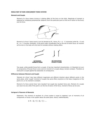
- 1. RESULTANT OF NON-CONCURRENT FORCE SYSTEM Moment and Couple Moment of a force means turning or rotating effect of the force on the body. Magnitude of moment is obtained by multiplying perpendicular distance (from the particular point on the line of action of the force) and the force. Moment of a force F about point A can be denoted as MA. Hence, MA = d1 . F (clockwise) while MB = 0 and MC = d2 . F (counter clockwise). If the point under consideration lies on the line of action force, its moment will be zero or the body will only tend to translate without rotating effect. Two equal, unlike parallel forces form a couple. It has two important characteristics. (1) Resultant (or sum of components of forces) force is zero and (2) moment of a couple always remains constant. Therefore at what point a couple applied has absolutely no consequence. Difference between Moment and Couple ‘Moment of a force’ may have different magnitude and different direction about different points in the same plane, while ‘couple’ (moment of couple) has same effect anywhere on the body irrespective of the point on it; or its moment is constant. Moment of a force cannot have ‘zero resultant’ but couple has resultant force zero. Moment of a couple can never be zero while if the point is on the line of action of the force, moment of force can be zero. Varignon’s Theorem of Moments Statement: The moment of resultant of a force system is equal to algebraic sum of moments of all components or forces in the system about the same point. Hence, mathematically, d ⋅ R = (d1 ⋅ F1 ) + (d2 ⋅ F2 ) + ...
- 2. Example: Replace the given system of forces acting on the beam AB shown in the figure, by (A) resultant and distance at which it acts from point A, (B) an equivalent force-couple system at A, and (C) an equivalent force-couple system at B. Solution: (A) Resultant and distance from point A The resultant is: ΣR = (300 − 1200 + 200 − 500) N R = 1200 N ↓ The distance from point A, using Varignon’s Theorem of Moments (VTM), CW positive: (1200 N) x = −(300N)(2m) + (1200N)(5m) − (200N)(7m) + (500N)(11m) x = 7.92 m Equivalent force system: (B) Single force couple system from point A For replacing the given system by force couple system at A, find the net (resulting) moment of forces at point A. Assume forces in CW rotation with respect to point A as positive. ΣMA = −(300N)(2m) + (1200N)(5m) − (200N)(7m) + (500N)(11m) ΣMA = 9500 N – m clockwise
- 3. (C) Single force couple system from point B Similarly at point B, assume forces in CW rotation with respect to point B as positive. ΣMB = −(500N)(1m) + (200N)(5m) − (1200N)(7m) + (300N)(10m) ΣMA = -4900 N – m counter clockwise Example: Replace the system of forces and couple by a single force system at A. Solution: 4 ( ) ΣR X = −75 N − 100 N = −155 N ← 5 3 ΣR Y = −200 N + 50 N − (100 N) = −210 N ↓ 5 Resultant Force: R = (− 155 N) 2 ( + − 210 N )2 R = 261 N Direction: − 210 N θ = tan −1 − 155 N θ = 53.57o
- 4. Equivalent moment about A, CW positive: 3 ΣM A = −(50N)(2m) − (80Nm) + (100N) (4m) 5 ΣMA = 60 N – m clockwise Equivalent force system: Example: If resultant moment at A of three coplanar forces is 88.4 N-m Clockwise, determine F. What is the resulting force of the system? Solution: 4 ΣMA = 88.4 N − m = (100N sin 30o )(0.8m) + (F) (1.6m) − (90N)(0.6m) 5 F = 80 N 3 ΣR X = −100N cos 30o − 90N + (80N) = −38.603 N 5 ← 4 ΣR y = −100N sin 30o − (80N) = −114 N 5 ↓ Resultant Force: R = 120.359 N Direction: θ = 71.29o
- 5. Reference: Engineering Mechanics by SP Nitsure © 2006 Technical Publications Pune