SlideShare a Scribd company logo
1 of 5
Download to read offline
Moment of a Couple
Ref: Hibbeler § 4.6, Bedford & Fowler: Statics § 4.4
A couple is a pair of forces, equal in magnitude, oppositely directed, and displaced by perpendicular
distance, d.
FB (= -FA)
d
FA
Since the forces are equal and oppositely directed, the resultant force is zero. But the displacement of
the force couple (d) does create a couple moment.
The moment, M, about some arbitrary point O can be calculated.
d
FA
FB
O
rA
rB
( )ABAA
BBAA
FrFr
FrFrM
−×+×=
×+×=
If point O is placed on the line of action of one of the forces, say FB, then that force causes no rotation
(or tendency toward rotation) and the calculation of the moment is simplified.
FA
FBO
r
AFrM ×=
This is a significant result: The couple moment, M, depends only on the position vector r between
forces FA and FB. The couple moment does not have to be determined relative to the location of a
point or an axis.
5
Example A: Moment from a Large Hand Wheel
The stem on a valve has two hand wheels: a small wheel (30 cm diameter) used to spin the valve
quickly as it is opened and closed, and a large wheel (80 cm diameter) that may be used to free a
stuck valve, or seat the valve tightly when it is fully closed.
30 cm
80 cm
If the operator can impose a force of 150 N on each side of the large wheel (a force couple), what
moment is imposed on the valve stem?
FA = 150 N
FB
= 150 N
rA
rB
Solution 1
As drawn, both the force and position vectors have x- and y-components. The vectors may be defined
as:
» F_A = [ 106.06 -106.06 0]; %Newtons
» r_A = [ 28.284 28.284 0]; %centimeters
» F_B = [-106.06 106.06 0] %Newtons
» r_B = [-28.284 -28.284 0]; %centimeters
The moment of the couple can be calculated using the cross product operator on the Matrix toolbar.
» M = cross(r_A,F_A) + cross(r_B,F_B); %Newton centimeters
» M = M/100 %Newton meters
M =
0 0 -120.0000
The result is a couple moment of 120 N⋅m directed in the –z direction (into the page).
Solution 2
Perhaps a more reasonable positioning of the axes for this problem might look like this:
FA = 150 N
FB = 150 N
r
x
y
In this case, the vector definitions become:
» F_A = [ 0 -150 0]; %Newtons
» r = [ 80 0 0]; %centimeters
Since the position vector r originates from the line of action of force FB, FB does not contribute to the
moment. The moment is then calculated as
» M = cross(r,F_A); %Newton centimeters
» M = M/100 %Newton meters
M =
0 0 -120
The result is, of course, the same no matter how the axes are situated.
Solution 3: Using Scalars
Finally, the problem can also be solved using a scalar formulation. The perpendicular distance
between the forces is 80 cm. With axes established as in Solution 2, the moment can be calculated
as
» F = 150; %Newtons
» d = 80; %centimeters
» M= d * F; %Newton centimeters
» M = M/100 %Newton meters
M =
120
The direction must be determined using the right-hand rule.
Annotated MATLAB Script Solution
%Solution 1
%
%Define the vectors
F_A = [ 106.06 -106.06 0]; %Newtons
r_A = [ 28.284 28.284 0]; %centimeters
F_B = [-106.06 106.06 0]; %Newtons
r_B = [-28.284 -28.284 0]; %centimeters
%Compute the moment using MATLAB's cross product function
M = cross(r_A,F_A) + cross(r_B,F_B); %Newton centimeters
%Convert to Newton meters
M = M/100; %Newton meters
fprintf('The resulting couple moment is = [ %1.2f %1.2f %1.2f ] (Nm)n', M)
%Solution 2
%
%Define the vectors
F_A = [ 0 -150 0]; %Newtons
r = [ 80 0 0]; %centimeters
%Compute the moment
M = cross(r,F_A); %Newton centimeters
%Convert to Newton meters
M = M/100; %Newton meters
fprintf('The resulting couple moment is = [ %1.2f %1.2f %1.2f ] (Nm)n', M)
%Solution 3
%
%Define the applied force and the perpendicular distance between the forces
F = 150; %Newtons
d = 80; %centimeters
%Compute the moment
M= d * F; %Newton centimeters
%Convert to Newton meters
M = M/100; %Newton meters
fprintf('The resulting couple moment is = %1.2f (Nm)n', M)
fprintf(' The direction must be determined using the right-hand rule.nn')
Example B: Moment from the Small Hand Wheel
The moment resulting from applying the same forces to the smaller hand wheel can be determined
using any of the three solution procedures outlined above. Solution 2 is shown here.
FA = 150 N
FB = 150 N r
x
y
%Example B: Moment from the Small Hand Wheel
% The moment resulting from applying the same forces to the
% smaller hand wheel can be determined using any of the three
% solution procedures above. Solution 2 is shown here.
%
%Define the vectors
F_A = [ 0 -150 0]; %Newtons
r = [ 30 0 0]; %centimeters
%Compute the moments
M = cross(r,F_A); %Newton centimeters
%Convert to Newton meters
M = M/100; %Newton meters
fprintf('The resulting couple moment for the smaller wheel is = [ %1.2f …
%1.2f %1.2f ] (Nm)n', M)

More Related Content

What's hot

Stress Mohr's circle
Stress Mohr's circleStress Mohr's circle
Stress Mohr's circleKingJyeWong
 
Finding a length given the angle of elevation
Finding a length given the angle of elevationFinding a length given the angle of elevation
Finding a length given the angle of elevationjseal
 
6161103 4.6 moment of a couple
6161103 4.6 moment of a couple6161103 4.6 moment of a couple
6161103 4.6 moment of a coupleetcenterrbru
 
Surveying assignment solutions 22.2.2015
Surveying assignment solutions 22.2.2015Surveying assignment solutions 22.2.2015
Surveying assignment solutions 22.2.2015V Vinayaka Ram
 
Shear force bending moment diagrams
Shear force bending moment diagramsShear force bending moment diagrams
Shear force bending moment diagramsKingJyeWong
 
Engineering Mechanice Lecture 03
Engineering Mechanice Lecture 03Engineering Mechanice Lecture 03
Engineering Mechanice Lecture 03Self-employed
 
Sfd and bmd engineering science n4
Sfd and bmd engineering science n4Sfd and bmd engineering science n4
Sfd and bmd engineering science n4Jude Jay
 
Rate of change and slope
Rate of change and slopeRate of change and slope
Rate of change and slopecathyguyer
 
Clasificación de los sistemas de fuerzas colineales
Clasificación de los sistemas de fuerzas colinealesClasificación de los sistemas de fuerzas colineales
Clasificación de los sistemas de fuerzas colinealesLuisBerengel
 
Linear regression
Linear regressionLinear regression
Linear regressionSreerajVA
 
Geometry 1.4 1.5
Geometry 1.4 1.5Geometry 1.4 1.5
Geometry 1.4 1.5Mark Ryder
 
241 wikarta-kuliah-iii-momen-gaya
241 wikarta-kuliah-iii-momen-gaya241 wikarta-kuliah-iii-momen-gaya
241 wikarta-kuliah-iii-momen-gayaEndraBackbrown
 

What's hot (20)

Stress Mohr's circle
Stress Mohr's circleStress Mohr's circle
Stress Mohr's circle
 
Finding a length given the angle of elevation
Finding a length given the angle of elevationFinding a length given the angle of elevation
Finding a length given the angle of elevation
 
6161103 4.6 moment of a couple
6161103 4.6 moment of a couple6161103 4.6 moment of a couple
6161103 4.6 moment of a couple
 
Surveying assignment solutions 22.2.2015
Surveying assignment solutions 22.2.2015Surveying assignment solutions 22.2.2015
Surveying assignment solutions 22.2.2015
 
Chapter I Moments
Chapter I MomentsChapter I Moments
Chapter I Moments
 
Shear force bending moment diagrams
Shear force bending moment diagramsShear force bending moment diagrams
Shear force bending moment diagrams
 
Engineering Mechanice Lecture 03
Engineering Mechanice Lecture 03Engineering Mechanice Lecture 03
Engineering Mechanice Lecture 03
 
Couple 136
Couple 136Couple 136
Couple 136
 
Sfd and bmd engineering science n4
Sfd and bmd engineering science n4Sfd and bmd engineering science n4
Sfd and bmd engineering science n4
 
powerpoint
powerpointpowerpoint
powerpoint
 
Rate of change and slope
Rate of change and slopeRate of change and slope
Rate of change and slope
 
Rate of Change & Slope
Rate of Change & SlopeRate of Change & Slope
Rate of Change & Slope
 
Clasificación de los sistemas de fuerzas colineales
Clasificación de los sistemas de fuerzas colinealesClasificación de los sistemas de fuerzas colineales
Clasificación de los sistemas de fuerzas colineales
 
311 Ch14 Version2
311 Ch14 Version2311 Ch14 Version2
311 Ch14 Version2
 
Linear regression
Linear regressionLinear regression
Linear regression
 
Geometry 1.4 1.5
Geometry 1.4 1.5Geometry 1.4 1.5
Geometry 1.4 1.5
 
Problemas esfuerzos combinados
Problemas esfuerzos combinadosProblemas esfuerzos combinados
Problemas esfuerzos combinados
 
241 wikarta-kuliah-iii-momen-gaya
241 wikarta-kuliah-iii-momen-gaya241 wikarta-kuliah-iii-momen-gaya
241 wikarta-kuliah-iii-momen-gaya
 
Desplazamientos trabajo virtual 1
Desplazamientos trabajo virtual 1Desplazamientos trabajo virtual 1
Desplazamientos trabajo virtual 1
 
348 project report
348 project report348 project report
348 project report
 

Viewers also liked (20)

Past
PastPast
Past
 
Freedom fighter
Freedom fighterFreedom fighter
Freedom fighter
 
Relative clauses
Relative clausesRelative clauses
Relative clauses
 
Articles
ArticlesArticles
Articles
 
Writing teens 2
Writing teens 2Writing teens 2
Writing teens 2
 
Independent Research Project Data
Independent Research Project DataIndependent Research Project Data
Independent Research Project Data
 
Seo services-india
Seo services-indiaSeo services-india
Seo services-india
 
Html5(2)
Html5(2)Html5(2)
Html5(2)
 
Beeman -linguistics and-anthropology_1_
Beeman -linguistics and-anthropology_1_Beeman -linguistics and-anthropology_1_
Beeman -linguistics and-anthropology_1_
 
Red swastik presentation
Red swastik presentationRed swastik presentation
Red swastik presentation
 
Finding Teachers Test
Finding Teachers TestFinding Teachers Test
Finding Teachers Test
 
M marinucci story_intern_chapt04b
M marinucci story_intern_chapt04bM marinucci story_intern_chapt04b
M marinucci story_intern_chapt04b
 
Luján and Sol ICT
Luján and Sol ICTLuján and Sol ICT
Luján and Sol ICT
 
Oliver twist
Oliver twistOliver twist
Oliver twist
 
Presentación
PresentaciónPresentación
Presentación
 
FemTalent/Escola
FemTalent/EscolaFemTalent/Escola
FemTalent/Escola
 
Olympic Games 2012
Olympic Games 2012Olympic Games 2012
Olympic Games 2012
 
Copia de catalogo 2013
Copia de catalogo 2013Copia de catalogo 2013
Copia de catalogo 2013
 
Horarios industrial mayo agosto 2013
Horarios industrial mayo agosto 2013Horarios industrial mayo agosto 2013
Horarios industrial mayo agosto 2013
 
Tenses
TensesTenses
Tenses
 

Similar to Moment of a Couple: Calculating Torque Applied to a Valve Stem

chap2_force_systems - Copy.ppt
chap2_force_systems - Copy.pptchap2_force_systems - Copy.ppt
chap2_force_systems - Copy.pptteseraaddis1
 
CHAPTER TENObjectiveA brief introduction of the basic concept
CHAPTER TENObjectiveA brief introduction of the basic conceptCHAPTER TENObjectiveA brief introduction of the basic concept
CHAPTER TENObjectiveA brief introduction of the basic conceptTawnaDelatorrejs
 
Mekanikateknik 140330175907-phpapp01
Mekanikateknik 140330175907-phpapp01Mekanikateknik 140330175907-phpapp01
Mekanikateknik 140330175907-phpapp01frans2014
 
6161103 4.3 moment of force vector formulation
6161103 4.3 moment of force   vector formulation6161103 4.3 moment of force   vector formulation
6161103 4.3 moment of force vector formulationetcenterrbru
 
Ch 3_rajib1.pptx
Ch 3_rajib1.pptxCh 3_rajib1.pptx
Ch 3_rajib1.pptxRajib Barua
 
Muzammil Abdulrahman PPT On Gabor Wavelet Transform (GWT) Based Facial Expres...
Muzammil Abdulrahman PPT On Gabor Wavelet Transform (GWT) Based Facial Expres...Muzammil Abdulrahman PPT On Gabor Wavelet Transform (GWT) Based Facial Expres...
Muzammil Abdulrahman PPT On Gabor Wavelet Transform (GWT) Based Facial Expres...Petroleum Training Institute
 
2nd codition of equilibrium
2nd codition of equilibrium2nd codition of equilibrium
2nd codition of equilibriumNestor Enriquez
 
2-vector operation and force analysis.ppt
2-vector operation and force analysis.ppt2-vector operation and force analysis.ppt
2-vector operation and force analysis.pptRanaUmair74
 
6161103 2.3 vector addition of forces
6161103 2.3 vector addition of forces6161103 2.3 vector addition of forces
6161103 2.3 vector addition of forcesetcenterrbru
 
Lecture Notes For Section 4.5
Lecture  Notes For  Section 4.5Lecture  Notes For  Section 4.5
Lecture Notes For Section 4.5Daniel Fernandez
 
6161103 4.11 chapter summary and review
6161103 4.11 chapter summary and review6161103 4.11 chapter summary and review
6161103 4.11 chapter summary and reviewetcenterrbru
 

Similar to Moment of a Couple: Calculating Torque Applied to a Valve Stem (20)

Moment
MomentMoment
Moment
 
Torque.ppt
Torque.pptTorque.ppt
Torque.ppt
 
Module 4
Module 4Module 4
Module 4
 
Torque
TorqueTorque
Torque
 
chap2_force_systems - Copy.ppt
chap2_force_systems - Copy.pptchap2_force_systems - Copy.ppt
chap2_force_systems - Copy.ppt
 
CHAPTER TENObjectiveA brief introduction of the basic concept
CHAPTER TENObjectiveA brief introduction of the basic conceptCHAPTER TENObjectiveA brief introduction of the basic concept
CHAPTER TENObjectiveA brief introduction of the basic concept
 
Mekanikateknik 140330175907-phpapp01
Mekanikateknik 140330175907-phpapp01Mekanikateknik 140330175907-phpapp01
Mekanikateknik 140330175907-phpapp01
 
Mekanika teknik
Mekanika teknikMekanika teknik
Mekanika teknik
 
Robotics lecture 3
Robotics lecture 3Robotics lecture 3
Robotics lecture 3
 
6161103 4.3 moment of force vector formulation
6161103 4.3 moment of force   vector formulation6161103 4.3 moment of force   vector formulation
6161103 4.3 moment of force vector formulation
 
Ch 3_rajib1.pptx
Ch 3_rajib1.pptxCh 3_rajib1.pptx
Ch 3_rajib1.pptx
 
Fourier series
Fourier seriesFourier series
Fourier series
 
Muzammil Abdulrahman PPT On Gabor Wavelet Transform (GWT) Based Facial Expres...
Muzammil Abdulrahman PPT On Gabor Wavelet Transform (GWT) Based Facial Expres...Muzammil Abdulrahman PPT On Gabor Wavelet Transform (GWT) Based Facial Expres...
Muzammil Abdulrahman PPT On Gabor Wavelet Transform (GWT) Based Facial Expres...
 
2nd codition of equilibrium
2nd codition of equilibrium2nd codition of equilibrium
2nd codition of equilibrium
 
2-vector operation and force analysis.ppt
2-vector operation and force analysis.ppt2-vector operation and force analysis.ppt
2-vector operation and force analysis.ppt
 
6161103 2.3 vector addition of forces
6161103 2.3 vector addition of forces6161103 2.3 vector addition of forces
6161103 2.3 vector addition of forces
 
Module 5
Module 5Module 5
Module 5
 
Lecture Notes For Section 4.5
Lecture  Notes For  Section 4.5Lecture  Notes For  Section 4.5
Lecture Notes For Section 4.5
 
Arithmetic mean
Arithmetic meanArithmetic mean
Arithmetic mean
 
6161103 4.11 chapter summary and review
6161103 4.11 chapter summary and review6161103 4.11 chapter summary and review
6161103 4.11 chapter summary and review
 

Moment of a Couple: Calculating Torque Applied to a Valve Stem

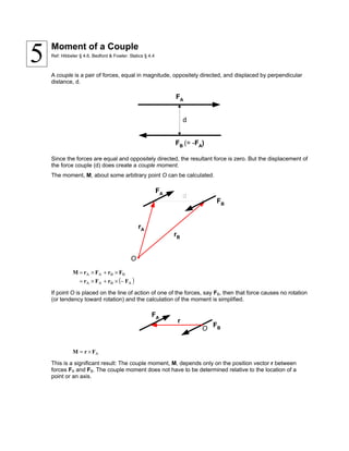
  • 1. Moment of a Couple Ref: Hibbeler § 4.6, Bedford & Fowler: Statics § 4.4 A couple is a pair of forces, equal in magnitude, oppositely directed, and displaced by perpendicular distance, d. FB (= -FA) d FA Since the forces are equal and oppositely directed, the resultant force is zero. But the displacement of the force couple (d) does create a couple moment. The moment, M, about some arbitrary point O can be calculated. d FA FB O rA rB ( )ABAA BBAA FrFr FrFrM −×+×= ×+×= If point O is placed on the line of action of one of the forces, say FB, then that force causes no rotation (or tendency toward rotation) and the calculation of the moment is simplified. FA FBO r AFrM ×= This is a significant result: The couple moment, M, depends only on the position vector r between forces FA and FB. The couple moment does not have to be determined relative to the location of a point or an axis. 5
  • 2. Example A: Moment from a Large Hand Wheel The stem on a valve has two hand wheels: a small wheel (30 cm diameter) used to spin the valve quickly as it is opened and closed, and a large wheel (80 cm diameter) that may be used to free a stuck valve, or seat the valve tightly when it is fully closed. 30 cm 80 cm If the operator can impose a force of 150 N on each side of the large wheel (a force couple), what moment is imposed on the valve stem? FA = 150 N FB = 150 N rA rB Solution 1 As drawn, both the force and position vectors have x- and y-components. The vectors may be defined as: » F_A = [ 106.06 -106.06 0]; %Newtons » r_A = [ 28.284 28.284 0]; %centimeters » F_B = [-106.06 106.06 0] %Newtons » r_B = [-28.284 -28.284 0]; %centimeters The moment of the couple can be calculated using the cross product operator on the Matrix toolbar. » M = cross(r_A,F_A) + cross(r_B,F_B); %Newton centimeters » M = M/100 %Newton meters M = 0 0 -120.0000 The result is a couple moment of 120 N⋅m directed in the –z direction (into the page). Solution 2 Perhaps a more reasonable positioning of the axes for this problem might look like this:
  • 3. FA = 150 N FB = 150 N r x y In this case, the vector definitions become: » F_A = [ 0 -150 0]; %Newtons » r = [ 80 0 0]; %centimeters Since the position vector r originates from the line of action of force FB, FB does not contribute to the moment. The moment is then calculated as » M = cross(r,F_A); %Newton centimeters » M = M/100 %Newton meters M = 0 0 -120 The result is, of course, the same no matter how the axes are situated. Solution 3: Using Scalars Finally, the problem can also be solved using a scalar formulation. The perpendicular distance between the forces is 80 cm. With axes established as in Solution 2, the moment can be calculated as » F = 150; %Newtons » d = 80; %centimeters » M= d * F; %Newton centimeters » M = M/100 %Newton meters M = 120 The direction must be determined using the right-hand rule.
  • 4. Annotated MATLAB Script Solution %Solution 1 % %Define the vectors F_A = [ 106.06 -106.06 0]; %Newtons r_A = [ 28.284 28.284 0]; %centimeters F_B = [-106.06 106.06 0]; %Newtons r_B = [-28.284 -28.284 0]; %centimeters %Compute the moment using MATLAB's cross product function M = cross(r_A,F_A) + cross(r_B,F_B); %Newton centimeters %Convert to Newton meters M = M/100; %Newton meters fprintf('The resulting couple moment is = [ %1.2f %1.2f %1.2f ] (Nm)n', M) %Solution 2 % %Define the vectors F_A = [ 0 -150 0]; %Newtons r = [ 80 0 0]; %centimeters %Compute the moment M = cross(r,F_A); %Newton centimeters %Convert to Newton meters M = M/100; %Newton meters fprintf('The resulting couple moment is = [ %1.2f %1.2f %1.2f ] (Nm)n', M) %Solution 3 % %Define the applied force and the perpendicular distance between the forces F = 150; %Newtons d = 80; %centimeters %Compute the moment M= d * F; %Newton centimeters %Convert to Newton meters M = M/100; %Newton meters fprintf('The resulting couple moment is = %1.2f (Nm)n', M) fprintf(' The direction must be determined using the right-hand rule.nn') Example B: Moment from the Small Hand Wheel The moment resulting from applying the same forces to the smaller hand wheel can be determined using any of the three solution procedures outlined above. Solution 2 is shown here. FA = 150 N FB = 150 N r x y
  • 5. %Example B: Moment from the Small Hand Wheel % The moment resulting from applying the same forces to the % smaller hand wheel can be determined using any of the three % solution procedures above. Solution 2 is shown here. % %Define the vectors F_A = [ 0 -150 0]; %Newtons r = [ 30 0 0]; %centimeters %Compute the moments M = cross(r,F_A); %Newton centimeters %Convert to Newton meters M = M/100; %Newton meters fprintf('The resulting couple moment for the smaller wheel is = [ %1.2f … %1.2f %1.2f ] (Nm)n', M)