Download to read offline

![MECHANICS OF SOLIDS
STRESSES & STRAINS (PART I)
Web: www.amiestudycircle.com Email: info@amiestudycircle.com Ph: +91 9412903929 12/44
AMIE(I) STUDY CIRCLE(REGD.)
A FOCUSSED APPROACH
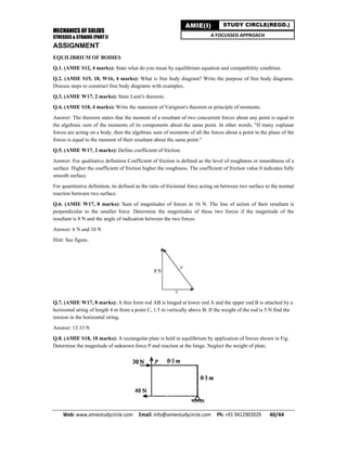
Example
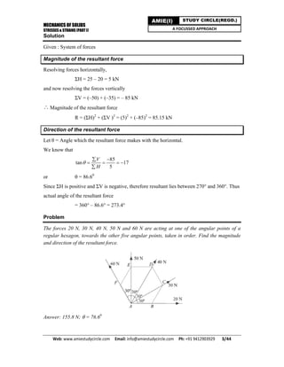
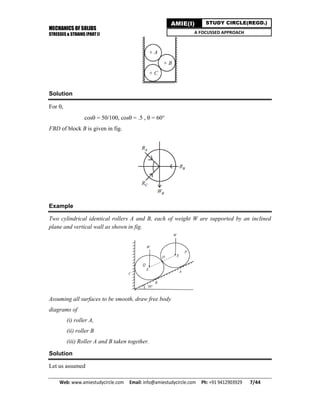
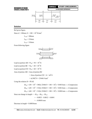
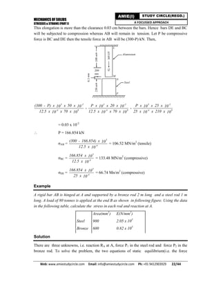
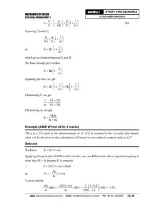
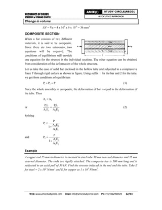
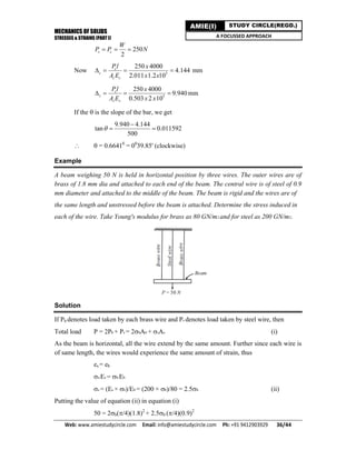
For the bar shown in Fig., calculate the reaction produced by the lower support on the bar.
Take E = 200 GN/m2. Find also the stresses in the bars.
Solution
Let R1 = reaction at the upper support;
R2 = reaction at the lower support when the bar touches it.
If the bar MN finally rests on the lower support,
we have
R1 + R2 = 55kN = 55000
N For bar LM, the total force = R1 = 55000 – R2 (tensile)
For bar MN, the total force =R2 (compressive)
L1 =extension of LM = [(55000 – R2) × 1.2]/[(110 × 10 – 6) × 200 × 109]
L2 = contraction of MN = [R2 × 2.4]/[(220 × 10–6) × 200 × 109]
In order that N rests on the lower support, we have from compatibility equation
L1 – L2 = 1.2/1000 = 0.0012 m
Or, [(55000 – R2) × 1.2]/[(110 × 10–6) × 200 × 109] – [R2 × 2.4]/[(220 × 10–6) ×
200 × 109] = 0.0012
on solving;
R2 = 16500N or, 16.5 KN
R1 = 55-16.5 = 38.5 KN
Stress in LM = R1/A1 = 38.5/110 × 10–6 = 0.350 × 10⁶ kN/m2
= 350 MN/m2
Stress in MN = R2/A2 = 16.5/220 × 10–6 = 0.075 × 10⁶ kN/m2
= 75 MN/m2](https://image.slidesharecdn.com/stressesandstrains1-200304045857/85/Stresses-and-strains-Part-1-12-320.jpg)
![MECHANICS OF SOLIDS
STRESSES & STRAINS (PART I)
Web: www.amiestudycircle.com Email: info@amiestudycircle.com Ph: +91 9412903929 13/44
AMIE(I) STUDY CIRCLE(REGD.)
A FOCUSSED APPROACH
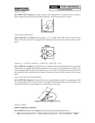
Example
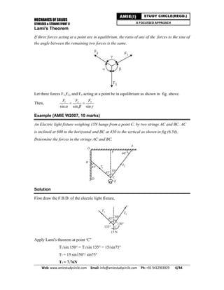
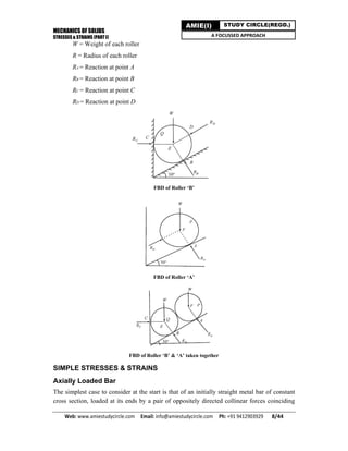
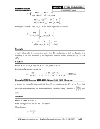
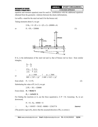
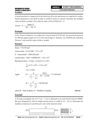
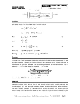
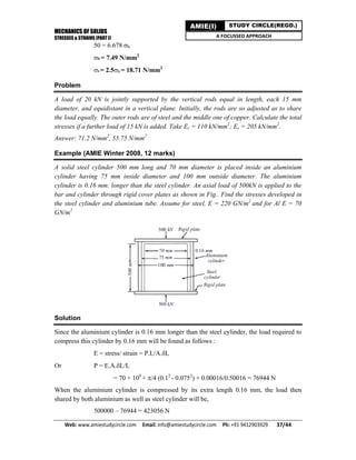
A member ABCD is subjected to point loads P1, P2, P3 andP4 as shown in figure.
Calculate the force P3 ,necessary for equilibrium if P1 = 120 kN, P2 = 220 kN and P4 = 160
kN. Determine also the net change in length of the member. Take E = 200 GN/m2
.
Solution
Modulus of elasticity E = 200 GN/ m2
= 2 × 10⁵ N/mm2
.
Considering equilibrium of forces along the axis of the member.
P1 + P3 = P2 + P4;
120 + P3 = 220 + 160
Force P3 = 220 + 160 – 120 = 260 kN
The forces acting on each segment of the member are shown in the free body diagrams shown
below:
Let L1, L2 and L3, be the extensions in the parts 1, 2 and 3 of the steel bar respectively.
Then,
Extension of segment AB
= [(120 × 103
) × (0.75 × 10³
)]/[1600 × (2 × 105
)] = 0.28125 mm
Compression of segment BC
= [(100 ×103
) × (1 × 10³
)]/[625 × (2 × 105
)] = 0.8 mm
Extension of segment CD
= [(160 ×103
) × (1.2 × 10³
)]/[900 × (2 × 105
)] = 1.0667 mm
Net change in length of the member
= l =0.28125 – 0.8 + 1.0667 = 0.54795 mm (increase)](https://image.slidesharecdn.com/stressesandstrains1-200304045857/85/Stresses-and-strains-Part-1-13-320.jpg)
![MECHANICS OF SOLIDS
STRESSES & STRAINS (PART I)
Web: www.amiestudycircle.com Email: info@amiestudycircle.com Ph: +91 9412903929 14/44
AMIE(I) STUDY CIRCLE(REGD.)
A FOCUSSED APPROACH
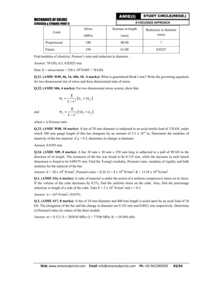
Problem
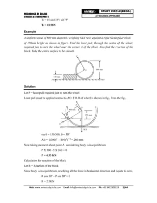
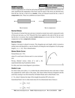
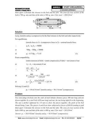
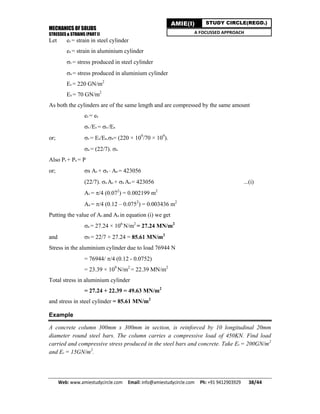
Find the total elongation of a steel bar as shown in following figure subjected to an axial
load of 1000 kN. E = 200 GPa.
Answer : 2.196 mm
Example
The bar shown in figure is subjected to an axial pull of 150 kN. Determine diameter of the
middle portion if stress there is limited to 125N/mm2
. Proceed to determine the length of this
middle portion if total extension of the bar is specified as 0.15 mm. Take modulus of elasticity
of bar material E = 2 × 10⁵
N/mm2
.
Solution
Each of the segment of this composite bar is subjected to axial pull P =150 kN.
Axial Stress in the middle portion 2 = Axial pull/Area = 150 × 103
/[(/4).(d2
2
)]
d2 = 39.1 mm
Since stress is limited to 125 N/mm2
, in the middle portion
125 = 150 × 103
/[(/4).(d2
2
)]
Diameter of middle portion
d2 = 39.1mm
(ii) Stress in the end portions, 1 = 3
= 150 × 103
/[(/4).(502
)] = 76.43 N/m2
Total change in length of the bar,
= change in length of end portions + change in length of mid portion
L = L1 + L2 + L3
= L1/E + L2/E + L3/E; Since E is same for all portions
= 1(L1 + L3)/E + L2/E
L1 + L3 = 300 – L2
Now putting all the values;](https://image.slidesharecdn.com/stressesandstrains1-200304045857/85/Stresses-and-strains-Part-1-14-320.jpg)
![MECHANICS OF SOLIDS
STRESSES & STRAINS (PART I)
Web: www.amiestudycircle.com Email: info@amiestudycircle.com Ph: +91 9412903929 15/44
AMIE(I) STUDY CIRCLE(REGD.)
A FOCUSSED APPROACH
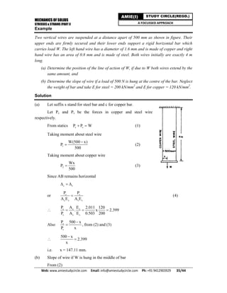
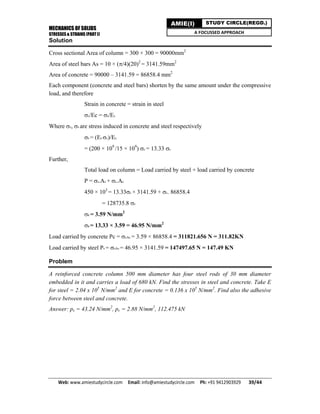
0.15 = [76.43(300 – L2)]/2 × 105
+ 125L2/2 × 105
L2 = 145.58 mm
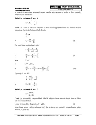
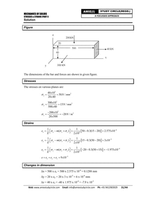
Example (AMIE Winter 2012, 8 marks)
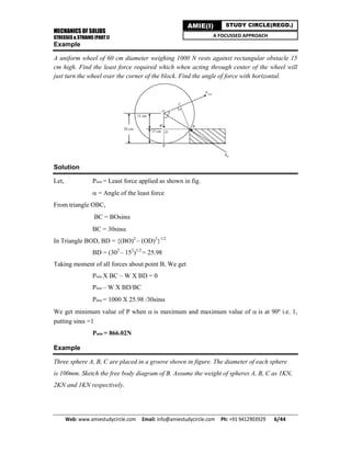
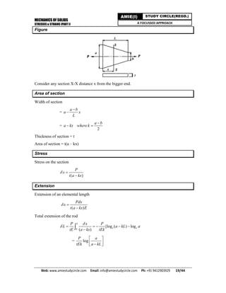
A bar of uniform cross sectional area “A” and length “L” hangs vertically from a rigid
support of the density of a material as kg/m3
. Derive the expression for maximum stress
induced and elongation produced in the bar due to its own weight.
Solution
See following figure
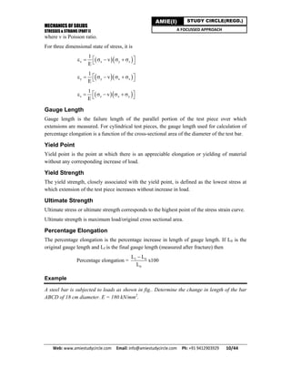
Consider a small section of length x, at a distance x from the free end. The deformation
is given by
.
sW x
A E
where Ws = weight of portion below the section = A.x.
( )
.
Ax x x x
A E E
Total deformation of the rod
2
0 2
L x gL
dx
E E
Maximum stress induced in the strip
Ax
x
A
](https://image.slidesharecdn.com/stressesandstrains1-200304045857/85/Stresses-and-strains-Part-1-15-320.jpg)
![MECHANICS OF SOLIDS
STRESSES & STRAINS (PART I)
Web: www.amiestudycircle.com Email: info@amiestudycircle.com Ph: +91 9412903929 16/44
AMIE(I) STUDY CIRCLE(REGD.)
A FOCUSSED APPROACH
Example (AMIE S2006, 2012, Winter 2015, 10 marks)
Find the change in length of circular bar of uniform taper.
Solution
The stress at any cross section can be found by dividing the load by the area of cross section
and extension can be found by integrating extensions of a small length over whole of the
length of the bar. We shall consider the following cases of variable cross section:
Consider a circular bar that tapers uniformly from diameter d1 at the bigger end to diameter
d2 at the smaller end, and subjected to axial tensile load P as shown in figure.
Let us consider a small strip of length dx at a distance x from the bigger end.
Diameter of the elementary strip:
1 1 2[( ) ]/dx d d d x L
= 1d kx ; where 1 2( ) /k d d L
Cross sectional area of strip
2 2
1( )
4 4
s xA d d kx
Stress in the strip
2
2 1
1
4
( )( )
4
x
x
P P P
A d kxc kx
Strain in strip
2
1
4
( )
x
x
P
E d kx E
Elongation of the strip
2
1
4
( )
x x
Pdx
l dx
d kx E
The total elongation of this tapering bar can be worked out by integrating the above
expression between limits x = 0 to x = L.](https://image.slidesharecdn.com/stressesandstrains1-200304045857/85/Stresses-and-strains-Part-1-16-320.jpg)
![MECHANICS OF SOLIDS
STRESSES & STRAINS (PART I)
Web: www.amiestudycircle.com Email: info@amiestudycircle.com Ph: +91 9412903929 20/44
AMIE(I) STUDY CIRCLE(REGD.)
A FOCUSSED APPROACH
Example (AMIE Winter 2007, 10 marks)
A steel bar AB of uniform thickness 2 cm, tapers uniformly from 100 mm to 50 mm in a length
of 400 mm. From first principles determine the elongation of plate; if an, axial tensile force
of 50 kN is applied on it. [E = 2 x 10⁵
N/mm2
]
Solution
Consider a small element of length dx of the plate, at a distance x from the larger end. Then
at this section,
Width Wx = 100 (100 50)( / 400) 100
8
x
x mm
Cross section area Ax = thickness x width = 2
10 100
8
x
mm
Stress
3
250 10
/
10(100 / 8)
s
x
P x
N mm
A x
Strain
3
5
5 10 1
(100 / 8)(2 10 ) 40(100 / 8)
x
x
x
E x x x
Elongation of the elementary length
40(100 / 8)
x x
dx
L xdx
x
The total change in length of the plate can be worked out by integrating the above identity
between the limits x = 0 and x = 400 mm.
i.e.
400 400
0 0
1
0.1386
40(100 / 8) 40 (100 / 8)
dx dx
L
x x
mm
Problem
A flat steel plate is of trapezoidal form. The thickness of the plate is 15 mm and it tapers
uniformly from a width of 60 mm to 10 mm in a length of 30 cm. If an axial force of 100 kN
is applied at each end, determine the elongation of the plate. Take E = 204 kN/mm2
.
Answer : 0.351 mm](https://image.slidesharecdn.com/stressesandstrains1-200304045857/85/Stresses-and-strains-Part-1-20-320.jpg)
![MECHANICS OF SOLIDS
STRESSES & STRAINS (PART I)
Web: www.amiestudycircle.com Email: info@amiestudycircle.com Ph: +91 9412903929 21/44
AMIE(I) STUDY CIRCLE(REGD.)
A FOCUSSED APPROACH
Problem
A steel bar AB of uniform thickness 15 mm, tapers uniformly from 60 mm to 10 mm in a
length of 300 mm. From first principles determine the elongation of plate; if an, axial tensile
force of 120 kN is applied on it. [E = 2.04 x 10⁵
N/mm2
]
Answer: = 0.422 mm
Example
A metal bar 5 cm x 5 cm section is subjected to an axial compressive load of 500 kN. The
contraction on a 20 cm gauge length is found to be 0.5 mm and the increase in thickness
0.045 mm. Find the value of Young’s modulus and Poisson’s ratio.
Solution
Given P = 500 kN, l=20 cm, Δl = 0.05 cm, Δt = 0.0045 cm.
Area of cross section A = 5 x 5 = 25 cm2
Longitudinal strain
ε = Δl/l = 0.05/20 = 0.0025 ( compressive)
stress σ = P/A = 500 x 103
/25 x 10-4
= 200 MPa (compressive)
Young’s Modulus
E = σ/ε = 200 x 106
/0.0025 = 80 GPa
Lateral strain
Δt/t = 0.0045/5 = 0.0009 (tensile)
Poisson’s Ratio
v = Lateral strain/Longitudinal = 0.0009/0.0025 = 0.36
Example
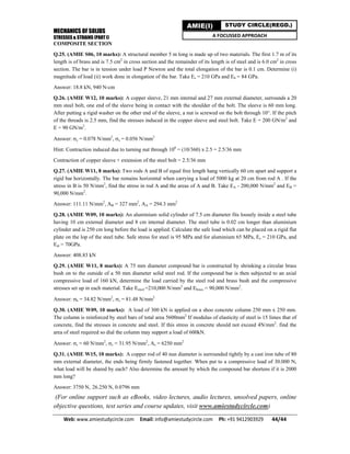
A 70 cm length of aluminium alloy bar is suspended from the ceiling so as to provide a
clearance of 0.03 cm between it and a 25 cm length of steel as shown in following figure.
Aal = 12.5 cm2
, Eal = 70 GN/m2
; As = 25 cm2
Es = 210 GN/m2
Determine the stress in the aluminium and in the steel due to a 300 kN load applied 50 cm
from the ceiling.
Solution
Elongation of AB under 300 kN load will be
3 -2
-4 9
300 x x 50 x10 10
12.5 x x 70 x10 10
= 1.71428 x 10⁻³
m = 0.171428 cm.](https://image.slidesharecdn.com/stressesandstrains1-200304045857/85/Stresses-and-strains-Part-1-21-320.jpg)
![MECHANICS OF SOLIDS
STRESSES & STRAINS (PART I)
Web: www.amiestudycircle.com Email: info@amiestudycircle.com Ph: +91 9412903929 24/44
AMIE(I) STUDY CIRCLE(REGD.)
A FOCUSSED APPROACH
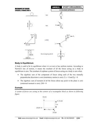
Example
A square bar of 25 mm side is held between two rigid plates and loaded by an axial pull
equal to 300 kN as shown in figure. Determine the reactions at end A and C and elongation
of the portion AB. Take E = 2 × 10⁵
N/mm2
.
Solution
Cross section area of the bar A = 25 × 25 mm2
Since the bar is held between rigid support at the ends, the following observations need to be
made:
Portion AB will be subjected to tension and portion BC will be under compression
Since each ends are fixed and rigid and therefore total Elongation;
Lab – Lbc = 0; Elongation in portion AB equals shortening in portion BC. i.e.,
Lab = Lbc
Sum of reactions equals the applied axial pull i.e., P = Ra + Rc
Apply second condition, we get
[Pab × Lab]/Aab.E = [Pbc × Lbc]/Abc.E
(Ra × 400)/(625 × 2 × 105
) = (Rc × 250)/(625 × 2 × 105
)
Rc = 1.6Ra (i)
Now apply third condition i.e., P = Ra + Rc
300 × 103
= Ra + 1.6 Ra
Ra = 1.154 × 10⁵
N; Rc = 1.846 × 10⁵
N
ELASTIC CONSTANTS
Modulus of Elasticity (E)
The quantity E, i.e. ratio of the unit stress to the unit strain, is the modulus of elasticity of the
material in tension, or, as it is often called Young’s modulus.
Bulk modulus (K)
It is defined as the ratio of uniform stress intensity to volumetric strain, within the elastic
limits and is denoted by K.](https://image.slidesharecdn.com/stressesandstrains1-200304045857/85/Stresses-and-strains-Part-1-24-320.jpg)
![MECHANICS OF SOLIDS
STRESSES & STRAINS (PART I)
Web: www.amiestudycircle.com Email: info@amiestudycircle.com Ph: +91 9412903929 28/44
AMIE(I) STUDY CIRCLE(REGD.)
A FOCUSSED APPROACH
Example
A steel bar of rectangular cross section 20 mm x 10 mm is subjected to a pull of 20 kN in the
direction of its length. Taking E = 0.2 x 10⁶
N/mm2
and m = 10/3, find the length of the sides
of the cross section and percentage decrease of area of cross section.
Solution
The strain in the direction of pull is
e1 =
p
m
=
P
AE
= 6
20000
20 x 10 x 0.2 x 10
= 5 x 10⁻⁴
Lateral strain = - 1e
m
= -
3
10
x 5 x 10-4
Hence 20 mm side is decreased by 20 x 1.5 x 10-4
= 0.0030 mm
10 mm side is decreased by 10 x 1.5 x 10-4
= 0.0015 mm
New area of cross section = (20 - 0.003)(10 - 0.0015) = ( 200 - 0.06)
% decrease of area of cross section =
0.06
200
x 100 = 0.03 Answer
Example
A piece of steel 200 mm long and 20 mm x 20 mm cross section is subjected to a tensile force
of 40 kN in the direction of its length. Calculate the change in volume. Take 1/m = 0.3. E =
2.05 x 10⁵
N/mm2
.
Solution
e1 = 5
40000
(20 x 20)(2.05 x )10
= 4.88 x 10⁻⁴
e2 = e3 = - 1e
m
= - 4.88 x 0.3 x 10-4
= -1.464 x 10⁻⁴
δV/V = e1 + e2 + e3 = [4.88 - (1.464 x 2)]10-4
= 1.952 x 10⁻⁴
V = 200 x 20 x 20 = 80000 mm3
δV = 1.952 x 80000 x 10-4
= 15.62 mm3
Answer
Problem
A piece of steel 1 metre long and 3 cm x 3 cm cross section is subjected to a tensile force of
120 kN in the direction of its length. Calculate the change in volume. Take 1/m = 0.29 and E
= 205 kN/mm2
.
Answer: 246 mm3](https://image.slidesharecdn.com/stressesandstrains1-200304045857/85/Stresses-and-strains-Part-1-28-320.jpg)
![MECHANICS OF SOLIDS
STRESSES & STRAINS (PART I)
Web: www.amiestudycircle.com Email: info@amiestudycircle.com Ph: +91 9412903929 42/44
AMIE(I) STUDY CIRCLE(REGD.)
A FOCUSSED APPROACH
Q.14. (AMIE W17, 6 marks): What do you mean by plain stress and plain strain condition?
Q.15. (AMIE W11, 5 marks): Express stresses x, y and z in terms of strains x, y and z using generalised
Hook’s law.
Q.16. (AMIE S05, 10 marks): The aluminium bar with a cross section area of 160 mm2
carries the axial loads
at the positions shown in following figure.
Given that E = 70 GPa, compute total change in length of the bar.
Answer: 4.227 mm
Q.17. (AMIE S08, 13, 8 marks): A mild steel bar, 6 m long, is 5 cm in diameter for 3 m of its length and 2.5
cm in diameter for the remaining length. The bar is in tension and the stress on the smallest section is 112 MPa.
Find the total elongation of the bar and the change in diameter at the smallest section. Given: E = 200 GPa and
Poisson's ratio = 0.15.
Answer: 0.21 cm, - 0.021 cm
Q.18. (AMIE S08, 13, 8 marks): A rod of square section of side D at one end tapers to a square section at the
other end. If its length is l, find the increase in length if it is subjected to an axial pull P.
Answer: Pl/EDd
Q.1. (AMIE S15, 6 marks): A bar of length 50 cm has varying cross-section. It carries a load of 25 kN. Find
the extension, if the cross- section is given by [5 + (x2
/100)] cm2
, where x is the distance from one end in cm.
Neglect weight of the bar. Take E = 2 x 10¹¹
N/m2
.
Answer: 0.004 cm
Hint:
50 50
20 0
7
5 (2 10 )
100
Pdx
d
x
x
Q.19. (AMIE S17, 8 marks): Find an expression for elongation of a bar of rectangular section and a conical
section due to self weight.
Answer: WL/2AE
ELASTIC CONSTANTS
Q.1. (AMIE S11, 17, W10, 16, 17, 5 marks): Define Poisson's ratio. Write the expressions for modulus of
rigidity (G) and bulk modulus (K) in terms of Young’s modulus of elasticity (E) and Poisson’s ratio ().
Establish the relation between E, K and G.
Q.2. (AMIE S17, 6 marks): Define bulk modulus. Deduce the relation
E = 3K (1 - 2)
Q.20. (AMIE W06, 10 marks): Define (i) Modulus of elasticity (ii) Modulus of rigidity (iii) Bulk modulus and
establish the relationship among them.
Q.1. (AMIE W11, 16, 6 marks): What is volumetric stress and volumetric strain? How is the volumetric strain
determined when a circular rod is loaded axially?
Q.2. (AMIE S06, 8 marks): A specimen of 15 mm diameter and 200 mm long is subjected to tensile test and
data at proportional and elastic limits were recorded as below:](https://image.slidesharecdn.com/stressesandstrains1-200304045857/85/Stresses-and-strains-Part-1-42-320.jpg)

The document discusses the fundamentals of stresses and strains in solids, detailing key concepts such as stress units, free body diagrams, equilibrium conditions, and examples of calculating forces and moments. It introduces Lami's theorem and methodology for analyzing systems with multiple forces, as well as the basic principles of normal stress and strain, including Hooke's Law. Additionally, it covers calculating changes in length for axially loaded bars under various loads, including examples and solutions to illustrate the application of these principles.