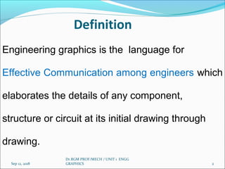
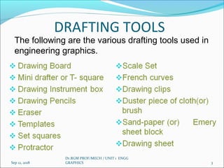
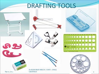
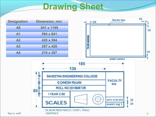
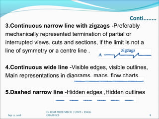
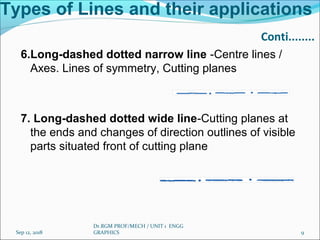
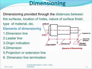
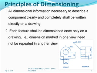
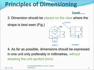
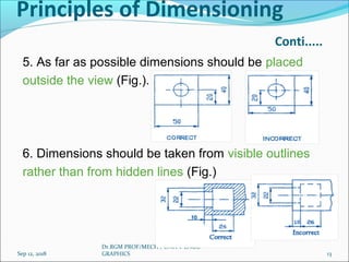
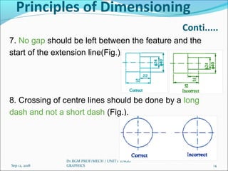
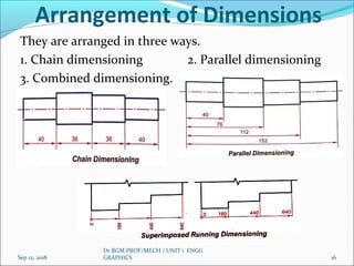
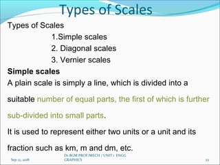
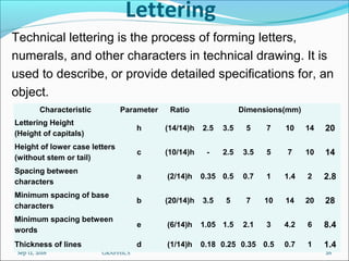
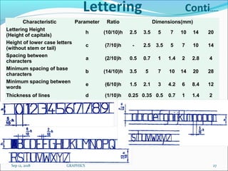
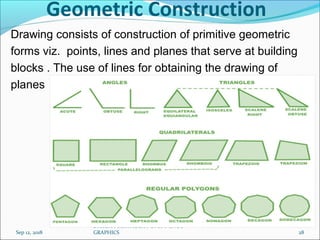
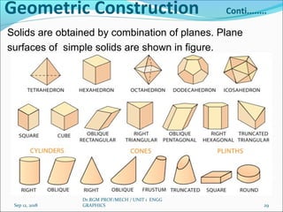
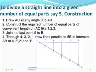
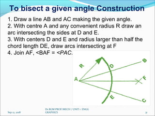
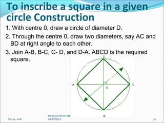
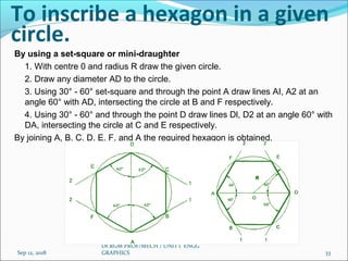
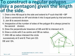
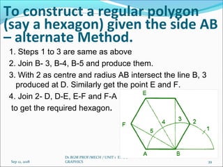
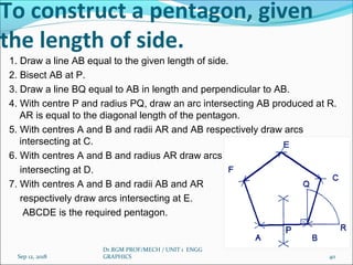
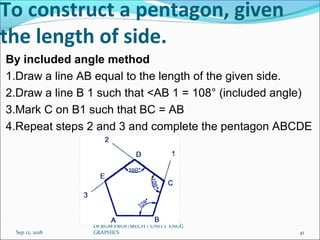
This document discusses engineering graphics and drafting tools used in technical drawings. It covers topics such as definition of engineering graphics, drafting tools, types of lines and their applications, dimensioning principles, lettering guidelines, geometric constructions, and scales. Specifically, it provides details on drawing sheets, drafting tools, types of lines based on appearance and usage, principles for dimensioning drawings, guidelines for technical lettering, examples of geometric constructions, and an overview of scales used in drawings.
CADmantra Technologies pvt. Ltd. is leading company in cad field .which are provided many types of cad couses i.e AUTOCAD,SOLIDWORK, CATIA, CRE-O, ANSYS,REVIT,STAAD.Pro and many type of courses used in tdrustial langauge
This report is a research on how to use DFM (Design For Manufacturing) engineering method to reduce the cost and time of manufacturing. Additionally it is describing (how to choose/which is the best) production(manufacturing) technology.
Basics of engineering drawing by Rishabh NatholiaRISHABH NATHOLIA
This is my work to make sure it is easy to understand the basic of Mechanical Engineer Drawing.It is a made for all and a quick bite to the very basics of engineering drawing. This data will also help the students to score more in their subjects. This will also help on design sector interviews.
If both the ends of a beam are supported by end supports then the beam is known as Simply Supported Beam. One end of the beam is supported by roller support and the other end is supported by a hinged or pinned support. Copy the link given below and paste it in new browser window to get more information on Simply Supported Beam Examples:- http://www.transtutors.com/homework-help/mechanical-engineering/bending-moment-and-shear-force/simply-supported-beam-examples.aspx
introduction of engineering graphics ,projection of points,lines,planes,solids,section of solids,development of surfaces,isometric projection,perspective projection
MATURATION DE CONCEPTS DE STRUCTURES AÉRONAUTIQUES ISSUS D’OPTIMISATION TOPOL...Hamza Ibrahmi
Maturation of topology optimization methods: Numerical strategy for optimal design of 3D aircraft components - Projet Fin d'études Master mécanique et ingénierie
Optimization of Surface Roughness Index for a Roller Burnishing Process Using...paperpublications3
Abstract: The main objective of this dissertation is to optimize the roughness index for a roller burnishing process. The factors have been identified from literature review. These barriers may be of market, cultural, human resource.management, financial, economical, attitudinal, environmental, geographical and technological type. Technology transfer barriers threats the movement of physical structure, knowledge, skills, organization value and capital from the developed to developing countries. Clear understanding of these barriers may help the practitioners to find out various ways to deal with them. This may further facilitate successful implementation of technology transfer. Technology transfer may be said to be successful if Transferor (seller) and the transferee (buyer) can effectively utilize the technology for business gain. The transfer involves cost and expenditure that should be agreed by the transferee and transferor. The process is affected by various factors that hinder Technology Transfer. These factors named Barriers. In the present work, Interpretive Structure Modeling (ISM) is used for the analysis and comparison of various factors important for Technology Transfer. The important parameters are identified and self-interaction matrixes proposed with the help of Interpretive Structure Modeling which evaluates the inhibiting power of these parameters. This index can be used in comparison of different factors responsible for Roller Burnishing Processes.
introduction of engineering graphics ,projection of points,lines,planes,solids,section of solids,development of surfaces,isometric projection,perspective projection
TOWARDS A UNIFIED IN-PROCESS GEOMETRIC MODEL FOR MULTIPLE MACHINING AND Layer...Liu PeiLing
There are many fabrication processes in modern manufacturing, but current modeling and simulation tools only simulate a few unit processes based on different geometry models. To overcome the data exchange problem between different models, this paper studies various in-process geometry models together with their working systems / prototypes for traditional manufacturing processes. Novel hybrid multiple-machining and layered manufacturing processes are presented to identify critical issues. Working towards a vision of pervasive modeling and simulation, a unified Voxel-based in-process geometry model for multiple-machining and layered manufacturing simulations is proposed and discussed.
In this presentation fuzzy logic controller using Fuzzy inference system is simulated and presented by simulating two different mechanical domain applications. Construction and approximation problem of a Multi input and single output (MISO) fuzzy system with normal implication and center-of-gravity defuzzifier is discussed for the first application. The Fuzzy Logic Designer application is used to model, design, simulate and test fuzzy inference systems for analyzing system behaviors. The unique feature of the Fuzzy Controller is that no mathematical models of the plant are required and the proposed controller is able to adequately estimate the bound functions on -line, which are required for the determination of the crisp control action. The approach of rapid prototyping is proposed to implement the Fuzzy Controller for second application so as to control a two link Robot Arm manipulator.
introduction of engineering graphics ,projection of points,lines,planes,solids,section of solids,development of surfaces,isometric projection,perspective projection
Saudi Arabia stands as a titan in the global energy landscape, renowned for its abundant oil and gas resources. It's the largest exporter of petroleum and holds some of the world's most significant reserves. Let's delve into the top 10 oil and gas projects shaping Saudi Arabia's energy future in 2024.
Industrial Training at Shahjalal Fertilizer Company Limited (SFCL)MdTanvirMahtab2
This presentation is about the working procedure of Shahjalal Fertilizer Company Limited (SFCL). A Govt. owned Company of Bangladesh Chemical Industries Corporation under Ministry of Industries.
Cosmetic shop management system project report.pdfKamal Acharya
Buying new cosmetic products is difficult. It can even be scary for those who have sensitive skin and are prone to skin trouble. The information needed to alleviate this problem is on the back of each product, but it's thought to interpret those ingredient lists unless you have a background in chemistry.
Instead of buying and hoping for the best, we can use data science to help us predict which products may be good fits for us. It includes various function programs to do the above mentioned tasks.
Data file handling has been effectively used in the program.
The automated cosmetic shop management system should deal with the automation of general workflow and administration process of the shop. The main processes of the system focus on customer's request where the system is able to search the most appropriate products and deliver it to the customers. It should help the employees to quickly identify the list of cosmetic product that have reached the minimum quantity and also keep a track of expired date for each cosmetic product. It should help the employees to find the rack number in which the product is placed.It is also Faster and more efficient way.
Water scarcity is the lack of fresh water resources to meet the standard water demand. There are two type of water scarcity. One is physical. The other is economic water scarcity.
Sachpazis:Terzaghi Bearing Capacity Estimation in simple terms with Calculati...Dr.Costas Sachpazis
Terzaghi's soil bearing capacity theory, developed by Karl Terzaghi, is a fundamental principle in geotechnical engineering used to determine the bearing capacity of shallow foundations. This theory provides a method to calculate the ultimate bearing capacity of soil, which is the maximum load per unit area that the soil can support without undergoing shear failure. The Calculation HTML Code included.
2. Definition
Engineering graphics is the language for
Effective Communication among engineers which
elaborates the details of any component,
structure or circuit at its initial drawing through
drawing.
Sep 12, 2018 2
Dr.RGM PROF/MECH / UNIT 1 ENGG
GRAPHICS
3. DRAFTING TOOLS
Sep 12, 2018 3
Dr.RGM PROF/MECH / UNIT 1 ENGG
GRAPHICS
The following are the various drafting tools used in
engineering graphics.
7. Types of Lines and their applications
1.Continuous narrow line-Dimension lines, Extension
lines, Leader lines, Reference lines, Short centre lines,
Projection lines, Hatching, Construction lines, Guide lines,
Outlines of revolved sections ,Imaginary lines of
intersection
2.Continuous narrow freehand line-Preferably manually
represented termination of partial or interrupted views,
Cuts and sections, if the limit is not a line of symmetry or
a Centre line·
Sep 12, 2018
Dr.RGM PROF/MECH / UNIT 1 ENGG
GRAPHICS 7
8. Conti........
3.Continuous narrow line with zigzags -Preferably
mechanically represented termination of partial or
interrupted views. cuts and sections, if the limit is not a
line of symmetry or a centre line .
4.Continuous wide line -Visible edges, visible outlines,
Main representations in diagrams, maps. flow charts.
5.Dashed narrow line -Hidden edges ,Hidden outlines
Sep 12, 2018
Dr.RGM PROF/MECH / UNIT 1 ENGG
GRAPHICS 8
9. Types of Lines and their applications
Conti........
6.Long-dashed dotted narrow line -Centre lines /
Axes. Lines of symmetry, Cutting planes
7. Long-dashed dotted wide line-Cutting planes at
the ends and changes of direction outlines of visible
parts situated front of cutting plane
Sep 12, 2018
Dr.RGM PROF/MECH / UNIT 1 ENGG
GRAPHICS 9
10. Dimensioning
Dimensioning provided through the distances between
the surfaces, location of holes, nature of surface finish,
type of material, etc.
Elements of dimensioning
1.Dimension line
2.Leader line
3.Origin indication
4.Dimension
5.Projection or extension line
6. Dimension line termination
Sep 12, 2018
Dr.RGM PROF/MECH / UNIT 1 ENGG
GRAPHICS 10
11. Principles of Dimensioning
I. All dimensional information necessary to describe a
component clearly and completely shall be written
directly on a drawing.
2. Each feature shall be dimensioned once only on a
drawing, i.e., dimension marked in one view need
not be repeated in another view.
Sep 12, 2018
Dr.RGM PROF/MECH / UNIT 1 ENGG
GRAPHICS 11
12. Principles of Dimensioning
Conti.....
3. Dimension should be placed on the view where the
shape is best seen (Fig.)
4. As far as possible, dimensions should be expressed
in one unit only preferably in millimetres, without
showing the unit symbol (mm).
Sep 12, 2018
Dr.RGM PROF/MECH / UNIT 1 ENGG
GRAPHICS 12
13. Principles of Dimensioning
Conti.....
5. As far as possible dimensions should be placed
outside the view (Fig.).
6. Dimensions should be taken from visible outlines
rather than from hidden lines (Fig.)
Sep 12, 2018
Dr.RGM PROF/MECH / UNIT 1 ENGG
GRAPHICS 13
14. Principles of Dimensioning
Conti.....
7. No gap should be left between the feature and the
start of the extension line(Fig.).
8. Crossing of centre lines should be done by a long
dash and not a short dash (Fig.).
Sep 12, 2018
Dr.RGM PROF/MECH / UNIT 1 ENGG
GRAPHICS 14
16. Arrangement of Dimensions
They are arranged in three ways.
1. Chain dimensioning 2. Parallel dimensioning
3. Combined dimensioning.
Sep 12, 2018
Dr.RGM PROF/MECH / UNIT 1 ENGG
GRAPHICS 16
17. Sep 12, 2018
Dr.RGM PROF/MECH / UNIT 1 ENGG
GRAPHICS 17
Set of Scales
Scales are used to make drawing of the objects to
proportionate size desired. These are made of wood,
steel or plastic.
Sep 12, 2018
Dr.RGM PROF/MECH / UNIT 1 ENGG
GRAPHICS 17
M1 M2 M3 M4 M5 M6 M7 M8
Scale on one edge 1:1 1:25 1:10 1:50 1:200 1:300 1:400 1:1000
Scale on other edge 1:2 1:5 1:20 1:100 1:500 1:600 1:800 1:2000
Scales for use on technical drawings(IS: 46-1988)
Category Category Recommended scales
Enlargeme
nt scales
50 : 1
5 : 1
20 : 1
2 : 1
10 : 1
Full size 1 : 1
Reduction
scales
1 : 2
1 : 20
1 : 200
1 : 2000
1 : 5
1 : 50
1 : 500
1 : 5000
1 : 10
1 : 100
1 : 1000
1 : 10000
18. Scale
Definition :
Scale is defined as the ratio of the linear dimension of
an element of an object as represented in the original
drawing to the linear dimension of the same element of
the object itself.
Full size scale
If we show the actual length of an object on a drawing,
then the scale used is called full size scale.
Sep 12, 2018
Dr.RGM PROF/MECH / UNIT 1 ENGG
GRAPHICS 18
19. Scale Conti…..
Reducing scale
If we reduce the actual length of an object so as to
accommodate that object on drawing, then scale used is
called reducing scale.
Enlarging scale
Drawings of smaller machine parts, mechanical
instruments,
watches, etc. are made larger than their real size. These are
said to be drawn in an increasing or enlarging scale.
Sep 12, 2018
Dr.RGM PROF/MECH / UNIT 1 ENGG
GRAPHICS 19
20. Representative Fraction (R.F)
The ratio of the drawing of an object to its actual size is
Called the representative fraction, usually referred to as
R.F.
R.F=Drawing of an object/It’s actual size(in same units)
For reducing scale, the drawings will have R.F. values of
Less than unity.
if 1 cm on drawing represents
1 m length of an object.
Sep 12, 2018
Dr.RGM PROF/MECH / UNIT 1 ENGG
GRAPHICS 20
21. Representative Fraction (R.F)
conti....
Increasing or enlarging scale, the R.F values will be
Greater than unity.
For example, when 1 mm length of an object is shown by
a length of 1cm on the drawing
Sep 12, 2018
Dr.RGM PROF/MECH / UNIT 1 ENGG
GRAPHICS 21
22. Types of Scales
Types of Scales
1.Simple scales
2. Diagonal scales
3. Vernier scales
Simple scales
A plain scale is simply a line, which is divided into a
suitable number of equal parts, the first of which is further
sub-divided into small parts.
It is used to represent either two units or a unit and its
fraction such as km, m and dm, etc.
Sep 12, 2018
Dr.RGM PROF/MECH / UNIT 1 ENGG
GRAPHICS 22
23. Types of Scales Conti.....
Plain scales , Diagonal Scales, Vernier Scale
Plain scales are used to read lengths in two units such as
metres and decimetres or to read the accuracy correct to
first decimal.
Diagonal scales are used to represent either three units
of measurements such as metres, decimetres,
centimetres
or to read to the accuracy correct to two decimals.
The diagonal scales, vernier scales are used to read very
Small units with accuracy.
They are used, when a diagonal Scale is inconvenient to
Sep 12, 2018
Dr.RGM PROF/MECH / UNIT 1 ENGG
GRAPHICS 23
24. Types of Scales Conti.....
Vernier scale
A vernier Scale consists of two parts, i.e., Main scale
and a vernier.
The main scale is a Plain scale divided into minor
divisions.
The vernier is also a scale used along with the main
scale to read the third unit, which is the fraction of
the second unit on the main scale.
Sep 12, 2018
Dr.RGM PROF/MECH / UNIT 1 ENGG
GRAPHICS 24
25. Types of Scales Conti.....
Least count: Least count the smallest distance
that can be measured accurately by the vernier
scale and is the vernier scale and is the difference
between a main scale division and a vernier scale
division.
Types of Verniers:
1. Forward vernier or direct vernier
2. Backward vernier or retrograde vernier
Sep 12, 2018
Dr.RGM PROF/MECH / UNIT 1 ENGG
GRAPHICS 25
26. Lettering
Technical lettering is the process of forming letters,
numerals, and other characters in technical drawing. It is
used to describe, or provide detailed specifications for, an
object.
Sep 12, 2018
Dr.RGM PROF/MECH / UNIT 1 ENGG
GRAPHICS 26
Characteristic Parameter Ratio Dimensions(mm)
Lettering Height
(Height of capitals)
h (14/14)h 2.5 3.5 5 7 10 14 20
Height of lower case letters
(without stem or tail)
c (10/14)h - 2.5 3.5 5 7 10 14
Spacing between
characters
a (2/14)h 0.35 0.5 0.7 1 1.4 2 2.8
Minimum spacing of base
characters
b (20/14)h 3.5 5 7 10 14 20 28
Minimum spacing between
words
e (6/14)h 1.05 1.5 2.1 3 4.2 6 8.4
Thickness of lines d (1/14)h 0.18 0.25 0.35 0.5 0.7 1 1.4
27. Lettering Conti.....
Characteristic Parameter Ratio Dimensions(mm)
Lettering Height
(Height of capitals)
h (10/10)h 2.5 3.5 5 7 10 14 20
Height of lower case letters
(without stem or tail)
c (7/10)h - 2.5 3.5 5 7 10 14
Spacing between
characters
a (2/10)h 0.5 0.7 1 1.4 2 2.8 4
Minimum spacing of base
characters
b (14/10)h 3.5 5 7 10 14 20 28
Minimum spacing between
words
e (6/10)h 1.5 2.1 3 4.2 6 8.4 12
Thickness of lines d (1/10)h 0.25 0.35 0.5 0.7 1 1.4 2
Sep 12, 2018
Dr.RGM PROF/MECH / UNIT 1 ENGG
GRAPHICS 27
28. Geometric Construction
Drawing consists of construction of primitive geometric
forms viz. points, lines and planes that serve at building
blocks . The use of lines for obtaining the drawing of
planes
Sep 12, 2018
Dr.RGM PROF/MECH / UNIT 1 ENGG
GRAPHICS 28
29. Geometric Construction Conti........
Solids are obtained by combination of planes. Plane
surfaces of simple solids are shown in figure.
Sep 12, 2018
Dr.RGM PROF/MECH / UNIT 1 ENGG
GRAPHICS 29
30. To divide a straight line into a given
number of equal parts say 5. Construction
Sep 12, 2018
Dr.RGM PROF/MECH / UNIT 1 ENGG
GRAPHICS 30
1. Draw AC at any angle θ to AB.
2. Construct the required number of equal parts of
convenient length on AC like 1,2,3.
3. Join the last point 5 to B
4. Through 4, 3, 2, 1 draw lines parallel to 5B to intersect
AB at 4',3',2' and 1'.
31. Sep 12, 2018
Dr.RGM PROF/MECH / UNIT 1 ENGG
GRAPHICS 31
1. Draw a line AB and AC making the given angle.
2. With centre A and any convenient radius R draw an
arc intersecting the sides at D and E.
3. With centers D and E and radius larger than half the
chord length DE, draw arcs intersecting at F
4. Join AF, <BAF = <PAC.
To bisect a given angle Construction
32. To inscribe a square in a given
circle Construction
1. With centre 0, draw a circle of diameter D.
2. Through the centre 0, draw two diameters, say AC and
BD at right angle to each other.
3. Join A-B, B-C, C- D, and D-A. ABCD is the required
square.
Sep 12, 2018
Dr.RGM PROF/MECH / UNIT 1 ENGG
GRAPHICS 32
33. To inscribe a hexagon in a given
circle.
By using a set-square or mini-draughter
1. With centre 0 and radius R draw the given circle.
2. Draw any diameter AD to the circle.
3. Using 30° - 60° set-square and through the point A draw lines AI, A2 at an
angle 60° with AD, intersecting the circle at B and F respectively.
4. Using 30° - 60° and through the point D draw lines Dl, D2 at an angle 60° with
DA, intersecting the circle at C and E respectively.
By joining A, B, C, D, E, F, and A the required hexagon is obtained.
Sep 12, 2018
Dr.RGM PROF/MECH / UNIT 1 ENGG
GRAPHICS 33
34. To inscribe a hexagon in a given
circle.
By using compass
1. With centre 0 and radius R draw the given circle.
2. Draw any diameter AD to the circle.
3. With centres A and D and radius equal to the radius of the circle draw
arcs intersecting the circles at B, F, C and E respectively.
4. ABC D E F is the required hexagon.
Sep 12, 2018
Dr.RGM PROF/MECH / UNIT 1 ENGG
GRAPHICS 34
35. To circumscribe a hexagon on a given
circle of radius R construction
1. With centre 0 and radius R draw the given circle.
2. Using 60° position of the mini draughter or 300
-
600
set square, circumscribe the hexagon as shown.
Sep 12, 2018
Dr.RGM PROF/MECH / UNIT 1 ENGG
GRAPHICS 35
36. To construct a hexagon, given
the length of the side
(a)Using set square
1. Draw a line AB equal to the side of the hexagon.
2. Using 30° - 60° set-square draw lines AI, A2, and
BI,B2.
3. Through 0, the point of intersection between the lines
A2 at D and B2 at E.
4. Join D,E
5. ABC D E F is the required hexagon.
Sep 12, 2018
Dr.RGM PROF/MECH / UNIT 1 ENGG
GRAPHICS 36
37. To construct a hexagon, given the
length of the side
(b) By using compass
1. Draw a line AB equal to the of side of the hexagon.
2. with centres A and B and radius AB, draw arcs
intersecting at 0, the centre of the hexagon.
3. With centres 0 and B and radius OB (=AB) draw arcs
intersecting at C.
4. Obtain points D, E and F in a similar manner.
Sep 12, 2018
Dr.RGM PROF/MECH / UNIT 1 ENGG
GRAPHICS 37
38. To construct a regular polygon
(say a pentagon) given the length
of the side.
1. Draw a line AB equal to the side and extend to P such that AB = BP
2. Draw a semicircle on AP and divide it into 5 equal parts by trial and error.
3. Join B to second division
4. Irrespective of the number of sides of the polygon B is always joined to
the second division.
5. Draw the perpendicular bisectors of AB and B2 to intersect at O.
6. Draw a circle with 0 as centre and OB as radius.
7. With AB as radius intersect the circle
successively at D and E.Then join CD.
DE and EA.
Sep 12, 2018
Dr.RGM PROF/MECH / UNIT 1 ENGG
GRAPHICS 38
39. To construct a regular polygon
(say a hexagon) given the side AB
– alternate Method.
1. Steps 1 to 3 are same as above
2. Join B- 3, B-4, B-5 and produce them.
3. With 2 as centre and radius AB intersect the line B, 3
produced at D. Similarly get the point E and F.
4. Join 2- D, D-E, E-F and F-A
to get the required hexagon.
Sep 12, 2018
Dr.RGM PROF/MECH / UNIT 1 ENGG
GRAPHICS 39
40. To construct a pentagon, given
the length of side.
1. Draw a line AB equal to the given length of side.
2. Bisect AB at P.
3. Draw a line BQ equal to AB in length and perpendicular to AB.
4. With centre P and radius PQ, draw an arc intersecting AB produced at R.
AR is equal to the diagonal length of the pentagon.
5. With centres A and B and radii AR and AB respectively draw arcs
intersecting at C.
6. With centres A and B and radius AR draw arcs
intersecting at D.
7. With centres A and B and radii AB and AR
respectively draw arcs intersecting at E.
ABCDE is the required pentagon.
Sep 12, 2018
Dr.RGM PROF/MECH / UNIT 1 ENGG
GRAPHICS 40
41. By included angle method
1.Draw a line AB equal to the length of the given side.
2.Draw a line B 1 such that <AB 1 = 108° (included angle)
3.Mark C on B1 such that BC = AB
4.Repeat steps 2 and 3 and complete the pentagon ABCDE
Sep 12, 2018
Dr.RGM PROF/MECH / UNIT 1 ENGG
GRAPHICS 41
To construct a pentagon, given
the length of side.