A variable speed drive can save 20% to 50% depending on the operating cycle and average flow. Applying variable speed drives to ventilation systems creates 20% to 70% in energy savings!
Electrical drive unit 1 as per IP university_EEEamrutapattnaik2
it is the complete Electrical Drive syllabus of the unit1. i 've tried a lot to merge everything in one PPT.it might be helpful for final year students.
i am also thankful to slideshare as I also collected all data and notes from this site too.
kindly share your suggestions for the improvement
1. The document discusses electric drives and their components. Electric drives use electric motors as prime movers and include a power source, power modulator, motor, control unit, and sensing unit.
2. Power modulators can be converters, variable impedance circuits, or switching circuits. Converters provide adjustable voltage/current/frequency to control motor speed and torque. Variable impedance circuits and switching circuits are used to control motor parameters.
3. Electric drives are classified as individual drives, group drives, or multimotor drives depending on how many motors are used to drive different loads. Individual drives use one motor for all loads while group drives use one motor connected to multiple loads through pulleys. Multimotor
Electric Drives and Controls Unit 1 IntroductionDr.Raja R
Electric Drives and Controls
Unit 1 Introduction
Block Diagram of Electric Drive
Power Source
Power Modulator
Load
Control Unit
Sensing Unit
Motor
Classification of Electrical Drives
Advantages of Electrical Drives
Disadvantages of Electrical Drive
Applications of Electrical Drives
The document provides information on assessing the energy performance of motors and variable speed drives. It discusses methods for determining motor efficiency through no-load, locked rotor, and full load tests. It also covers factors that affect motor efficiency like loading, temperature, and stray losses. The document then discusses applications of variable speed drives and factors for successful implementation like torque requirements, efficiency, and power factor. Key points on evaluating energy savings with variable speed applications are also summarized.
The document discusses three types of electric braking for DC motors: dynamic braking, plugging braking, and regenerative braking. Dynamic braking involves disconnecting the armature from the power supply and connecting it to an external resistor, causing current to flow in the opposite direction and slow the motor. Plugging braking rapidly changes the armature connection to reverse polarity, generating braking torque. Regenerative braking uses a chopper to allow the motor to act as a generator, returning energy to the power supply. Examples of calculations for braking power, time, and other parameters are also provided.
1. The document discusses the design of a new engine coolant testing rig built in association with ARAI to test materials under high pressure and temperature.
2. The old rig lacked safety features, automation, and had problems with leakage. The new rig addresses these issues with a touchscreen interface, alarms, automated readings, and improved piping and insulation.
3. The new rig is more compact and safe to operate while still providing accurate results according to industry standards. It aims to eliminate human intervention and downtime through the use of modern technologies.
This document discusses the design of a smart shock absorber that can generate electricity from the vibration energy of a vehicle's suspension system. It proposes using a rack and pinion gear connected to an alternator to convert the reciprocating motion of the shock absorber into rotational motion that can power the alternator. The system would charge the vehicle's battery to provide power for vehicle accessories. It estimates that installing such a system on all four wheels could generate 7.5 kWh of electricity from a suspension displacement of 25mm per meter traveled. The system would reuse vibration energy that is currently lost as heat and provide electricity without drawing power from the vehicle engine.
The document provides information on the construction, working principle, and types of transformers. It begins by explaining the necessity of transformers in electrical power systems for stepping up and down voltages. The key points are:
- Transformers transfer power between circuits through electromagnetic induction without changing frequency. They have a primary and secondary winding wound around an iron core.
- Transformers can be used to step up or step down voltages depending on the ratio of turns in the primary and secondary windings. The voltage transformation ratio is equal to the ratio of turns.
- An ideal transformer has zero resistance windings, infinite core permeability, and is lossless. The voltage induced in each winding is directly proportional to its turns and the rate
A PROJECT REPORT SIM & SPEED CONTROL OF INDUCTIO DRIVEPawan Kumar
The document discusses speed control methods for three-phase induction motors. It analyzes the transients during starting of an induction motor with different machine parameters. It then examines various speed control methods including variable rotor resistance, variable stator voltage, and constant V/f control. Simulation results are presented to show the torque-speed characteristics for each method. Vector control is also introduced, which allows independent control of torque and flux.
This document describes the design of a self-charging electric bicycle. It consists of a bicycle, battery, DC brushless motor, alternator, gear mechanism, and other components. The alternator generates power from pedaling that is stored in the battery. The motor uses power from the battery to drive the rear wheel. A gear system connects the pedaling to the alternator and motor. The system allows the bicycle to be powered by either pedaling or the motor using stored energy from the alternator.
This document provides an overview of induction and synchronous motor fundamentals, including:
- Synchronous motors operate at synchronous speed and have fixed stator windings connected to AC power, with a separate DC excitation source for the rotor. Induction motors have no separate power source for the rotor; current is induced in the rotor by the stator field.
- Synchronous motors can operate at unity or leading power factor by adjusting rotor excitation, while induction motors operate at lagging power factor.
- Common induction motor components include the squirrel cage rotor and wound stator. Synchronous motor starting methods include using a starting resistor or reduced voltage.
- Motors have different enclosure types for protection from environmental factors
An electric drive is a system that controls the motion of an electric motor. It consists of an electric power source, power modulators to regulate power flow from the source to the motor, a motor, sensors for feedback, and a controller. Power modulators can include AC to DC converters, DC to DC converters, and AC to AC converters. The type of motor used depends on factors like the load characteristics. Sensors measure parameters like motor speed and current. The controller then generates control signals to the power modulator based on sensor feedback to extract the desired output. Electric drives are used in applications like transportation systems, rolling mills, machine tools, and pumps.
This document summarizes a handbook on selecting energy-efficient electric motors. It was created to help industry identify opportunities to save costs by using high-efficiency motors. The handbook covers factors to consider when purchasing motors, such as efficiency, economics, and performance. It also provides guidance on launching motor improvement programs to realize energy and cost savings. The overall goal is to educate industry on replacing standard motors with energy-efficient options where cost-effective.
ZERO SPEED AND EMERGENCY BRAKING SYSTEM FOR ELECTRICAL OVERHEAD TRAVELLING CRANEIAEME Publication
In this paper, zero speed is achieved in drive motor of an Electrical Overhead
Travelling (EOT) crane by means of a dynamic braking system. There are two modes
in the crane operation. The first one is running mode and another one is braking
mode. In the zero speed braking, an induction motor is converted as a braking
mechanism. The dynamic braking circuit is activated during the braking mode. In
EOT crane, a thruster brake system is mostly used and it is an electro-mechanical
device. The thruster brake is installed between the drive motor and gear box for
controlling the load though the electric power is failed. The thruster brake is used to
retard the rotating speed of motor shaft and to stop it at desired position. The Thruster
brake and drive motor are energized simultaneously to run the crane/hoist is called
the running mode and stop the crane/hoist by both are de-energized is called the
braking mode. A small time difference (time clip) between the function of motor and
thruster causes huge impact pulse on the gear box/shaft. This impact pulse may
diminish the gear box/shaft progressively that cause load drop accident. For
avoiding/minimizing the time clip, the drive motor is converted as a braking device
during the braking mode. The drive motor will be turned to zero speed instead of deenergized.
This document provides information about different types of DC motor starters and AC motor starters. It discusses two point, three point, and four point starters for DC motors. It explains how each type protects the motor from high starting currents and overloads. It also covers various AC motor starting methods like auto transformer starting, star-delta starting, and direct online starting. Star-delta and auto transformer starting reduce the starting current by initially applying a lower voltage to the motor. Direct online starting applies full voltage but is only suitable for small motors due to the large starting currents involved.
1) The document discusses direct torque control (DTC) of induction motors using space vector modulation (SVM-DTC). DTC aims to control torque and flux of the motor but causes current and torque ripple.
2) SVM-DTC is proposed to reduce ripple by increasing the number of available voltage vectors applied to the motor. This provides benefits like lower torque ripple and current distortion.
3) The document then provides background on induction motors, including their construction, operation, speed control, and starting methods before discussing DTC and SVM-DTC in more detail.
This document summarizes research on analyzing the stability of an electrical power system with a single machine using the fourth order Runge-Kutta method. The study examines the critical clearing angle and critical clearing time for a generator in a power plant system connecting to an infinite bus. Simulation results show the system is stable for fault clearing times of 0.25 and 0.35 seconds, as the disconnection angle is less than the critical clearing angle of 97.78 degrees. However, the system is unstable for clearing times of 0.4 and 0.6 seconds, as the disconnection angle exceeds the critical clearing angle. The research concludes the fourth order Runge-Kutta method can accurately determine stability limits in terms of critical clearing angle
IRJET - Regenerative Braking for an Electric CarIRJET Journal
This document discusses regenerative braking systems for electric vehicles. It begins with an introduction to electric vehicles and how they store energy from the grid in batteries. When braking, regenerative braking systems use the electric motor as a generator to capture the kinetic energy of the moving vehicle and store it back in the batteries. This extends the driving range.
The document then describes two types of regenerative braking systems - serial and parallel. Serial systems integrate regenerative and friction braking control for more consistent pedaling. Parallel systems operate the braking systems in tandem without integrated control. The document also discusses regenerative ratio, which measures the efficiency of energy regeneration, and concludes regenerative braking is most effective at higher speeds
This document provides an overview of a course on electrical drives and control. It includes 5 units that cover topics such as drive motor characteristics, starting methods, speed control of DC and AC drives using conventional and solid state methods. The introduction defines electric drives and lists their basic elements and functions. It also describes factors that influence the choice of electrical drives such as steady state operation requirements, transient operation requirements, cost considerations, and environmental factors. Heating and cooling curves are also introduced to explain temperature rise in electric machines.
Speed control of three phase im by vf open and close loop methodeSAT Journals
This document presents a simulation of speed control for a three-phase induction motor using open-loop and closed-loop V/F control methods. In the open-loop method, a PWM inverter drives the motor and the torque is observed to remain constant with varying rotor speed. In the closed-loop method, a PI controller provides feedback to vary the supply frequency to maintain a constant V/F ratio. Simulation results in MATLAB Simulink show that closed-loop control provides superior speed regulation compared to the open-loop method.
An electric motor is an electrical machine that converts electrical energy into mechanical energy. Most electric motors operate through the interaction between the motor's magnetic field and electric current in a wire winding to generate force in the form of rotation of a shaft.
The document discusses a student project to design and build a DC motor. It includes sections on the motor model, materials and costs, specifications of the brush motor designed, and background information on DC motors and their operation. It also compares the advantages and disadvantages of DC motors and AC motors.
The document presents a presentation on dynamic modeling of DC motor drives. It discusses different types of DC drives including single phase, three phase, and DC-DC converter drives. It also provides the generalized electrical diagram and dynamic model of a DC motor, describing the stator inductance and resistance, and how the electrical equation for a DC motor can be derived using Laplace transforms. The dynamic model expresses the stator current as a function of the stator gain and time constant.
Self Power Generating Electrical BicycleIRJET Journal
This document describes a design for a self-power generating electrical bicycle. The bicycle generates its own power through a dynamo connected to the rear wheel and flywheel. This powers a motor that drives the rear wheel, eliminating the need for external charging. The system includes a DC generator, permanent magnet DC motor, flywheel for storing rotational energy, housing to connect components, and multi-crank freewheel to drive the rear wheel from the motor. This design aims to overcome limitations of electric bicycles that have a limited range from external battery charging.
Design and Analysis of Drive System with Slip Ring Induction Motor for Electr...IJPEDS-IAES
The use of Squirrel Cage Motor for Traction has revolutionised the motive power of a Locomotive. The Asynchronous Motor is rugged, has high starting Torque, very smooth Voltage and Speed control as compared to a DC Series Motor. When looking at the Traction perspective, a Wound Rotor Induction Motor can be an alternative to the Squirrel Cage Motor as it has higher starting Torque at lower starting current and better efficiency than a Squirrel Cage Motor. The Slip Power Recovery scheme also plays a proactive role as there can be substantial savings of energy in case of a Wound Rotor Induction Motor as the Slip Power recovered can be used to drive the Auxiliary Loads of the Locomotive and also for powering the trailing Passenger Cars. A detailed design and analysis of a Drive System with Wound Rotor Induction Motor for Electric Traction is presented in this Research Paper.
An AC motor operates using the interaction between a rotating magnetic field in the stator created by AC current and a magnetic field in the rotor. The stator is the stationary part containing windings that generate the magnetic field, while the rotor is the rotating part. Induction motors are the most common type and have a wound stator and rotor. In an induction motor, currents induced in the rotor by the stator create rotation, while in a synchronous motor the rotor carries its own magnetic field from a separate DC source and locks to the rotating magnetic field frequency. Synchronous motors have constant synchronous speed regardless of load but require an external starting mechanism, while induction motors have self-starting torque but a speed that decreases slightly with increasing load
Interfacing and Commissioning of Motor and Drive to the Tandem test jigIJERA Editor
The motors and drives have wide applications from servos to traction and it is mainly used in automation industry, CNC machines and robots. The application of interfacing and commissioning of motor and drive to the tandem test jig helps to achieve improved reliability and cost effectiveness. This paper mainly describes how motors and drive system is interfaced to tandem test jig.BG605 motor grader vehicle is used for grading operation and bank cutting operation of roads. Tandem is a part of BG605 Motor grader equipment and it is used for transmission of power in the equipment. Testing of the tandem before assembling on to the vehicle is very much essential.
International Journal of Engineering Research and Applications (IJERA) aims to cover the latest outstanding developments in the field of all Engineering Technologies & science.
International Journal of Engineering Research and Applications (IJERA) is a team of researchers not publication services or private publications running the journals for monetary benefits, we are association of scientists and academia who focus only on supporting authors who want to publish their work. The articles published in our journal can be accessed online, all the articles will be archived for real time access.
Our journal system primarily aims to bring out the research talent and the works done by sciaentists, academia, engineers, practitioners, scholars, post graduate students of engineering and science. This journal aims to cover the scientific research in a broader sense and not publishing a niche area of research facilitating researchers from various verticals to publish their papers. It is also aimed to provide a platform for the researchers to publish in a shorter of time, enabling them to continue further All articles published are freely available to scientific researchers in the Government agencies,educators and the general public. We are taking serious efforts to promote our journal across the globe in various ways, we are sure that our journal will act as a scientific platform for all researchers to publish their works online.
The document discusses various types of electric motors, including DC motors, induction motors, synchronous motors, and stepper motors. It provides information on their working principles, characteristics, and applications. Some key points covered are: DC series motors have high starting torque; stepper motors work in steps in response to input pulses; single-phase induction motors are commonly used in household fans; synchronous generators supply both active and reactive power while asynchronous generators only supply active power.
The document discusses power consumption in clutch and servo motors used in sewing machines. It aims to compare the power consumption and costs of the two motor types through measuring their usage during different garment operations. The objectives are to determine the more efficient and cost-effective option between clutch and servo motors. Clutch motors are commonly used in small Pakistani industries due to their lower price compared to servo motors, but have higher electricity consumption and running costs.
This document discusses AC motors, including three-phase induction motors, single-phase induction motors, and brushless DC motors. It provides details on their construction, operation principles, advantages, limitations, torque-speed characteristics, and speed control methods. Three-phase induction motors are widely used due to their simple and rugged construction, reliability, low cost, and high efficiency. Single-phase induction motors require auxiliary circuits for self-starting. Methods to control induction motor speed include variable voltage variable frequency control and field oriented control.
This document discusses traction motors, which are electric motors that provide rotational torque, usually for converting into linear motion. Traction motors are used in electric rail vehicles. The document outlines key mechanical characteristics of traction motors such as robustness and small size. It also discusses important electrical characteristics like high starting torque and regenerative braking capability. Finally, it examines different types of traction motors including DC series motors and discusses factors driving increased global demand for traction motors.
EE6801 - Electric Energy Generation Utilisation and Conservationrmkceteee
This document provides information about electric drives and traction. It defines electric drives as systems that employ electric motors for supplying mechanical energy for motion control. It lists the main parts of electric drives and their applications. It discusses various types of duty cycles for electric drives and different methods of electric drive operation and speed control of DC and induction motors. It also covers topics like regenerative braking, traction systems, energy consumption factors and braking methods.
IRJET- IoT based Energy Efficient Ceiling Fan with BLDC Motor for Home Automa...IRJET Journal
This document describes a project to develop an energy efficient ceiling fan that can be controlled by smartphone using Internet of Things (IoT) technology. It uses a brushless DC motor powered by a switching power supply via a closed loop controller. An ESP8266 WiFi module is incorporated to allow control via a smartphone app. Brushless DC motors offer advantages over brushed DC motors like higher efficiency and reliability. The methodology involves using a microcontroller in the ESP module to generate control signals for motor speed and direction. An Android app is developed for the user interface. This allows remote control of the ceiling fan speed and provides home automation capabilities while saving energy.
Comparative study of electrical motors for ceiling fan applicationIAEME Publication
This document compares different types of motors used for ceiling fan applications, including single phase induction motors, universal motors, and brushless DC (BLDC) motors. It finds that BLDC motors provide benefits over traditional induction motors used in ceiling fans, including higher efficiency, better speed regulation, and ability to achieve higher energy efficiency ratings. A MATLAB model of a BLDC motor-driven ceiling fan is presented and analyzed, showing performance advantages in starting torque, speed control, and airflow compared to single phase induction motors commonly used in ceiling fans. While BLDC motors have a higher cost, the document concludes they can provide better performance and increased energy efficiency compared to traditional ceiling fan motors.
These slides presents an overview of different wind generator systems and their comparisons. Later of the slides the modelling and control strategies of wind generators will be discussed.
DC motors generate torque directly from DC power using internal commutation and stationary magnets. Brushless DC motors use rotating magnets and stationary coils. AC motors have a stationary stator with coils powered by AC current to generate a rotating magnetic field, and a rotor given torque.
DC motors offer excellent speed control but require more maintenance due to brushes. AC motors are cheaper, more reliable with no brushes, allow for speed variation, and have high power factors, making them suitable for most industrial applications powered by AC sources. Both motor types have advantages dependent on the application.
Over-sizing of electric motors is a major cause of energy inefficiency. Motors are often sized larger than needed to drive loads, resulting in operation at partial capacity where efficiency drops significantly. Downsizing an oversized 30kW motor operating at 30% load from 75% to 85% efficiency using a 15kW motor could save 1.4kW annually, paying back the replacement cost within 6 months based on annual operating hours and local electricity rates. Proper motor sizing along with efficient motor designs and controls can achieve substantial energy savings given motors consume over half of industrial electricity usage globally.
This document discusses different types of electric motors:
1. Permanent magnet synchronous motors have constant torque output but are expensive and available only in small sizes. They are used in precision equipment.
2. Stepped motors move in discrete steps and have multiple coil phases. Variable-reluctance stepped motors work by aligning the rotor with the stator's magnetic field. Permanent magnet stepped motors produce more torque but require reversing current to change direction.
3. Brushless DC motors have electronically controlled commutation without brushes, making them more efficient than brushed DC motors. They are used in computer hard drives and other applications.
Optimization of controlling of performance characteristics of induction moIAEME Publication
This document summarizes an article from the International Journal of Electrical Engineering and Technology that proposes a fuzzy logic based online efficiency optimization control for an indirect vector controlled induction motor drive system. The control aims to minimize input power by decrementing rotor flux until the lowest power point is reached. This is done without requiring knowledge of motor parameters and is insensitive to parameter changes. Fast convergence is achieved using an adaptive excitation current step size, and low frequency torque pulsations are suppressed via feedforward compensation. The control scheme is described and mathematical models of the induction motor, electrical systems, and mechanical systems are provided.
This document discusses regenerative braking in electric vehicles. It begins by introducing regenerative braking and its importance for electric vehicles in conserving electrical energy. It then provides details on the components and design of a regenerative braking system, including using an induction motor, alternator, rectifier, battery, transformer and load. The document describes the block diagram and working of the system, where kinetic energy recovered during braking is used to charge the battery and power a light bulb load.
This document provides an overview of different types of electric motors, including DC motors, stepper motors, and their operating principles. It discusses conventional brushed DC motors and how they work using commutator and brushes. Brushless DC motors are also covered, noting they use electronic commutation instead of mechanical brushes. Stepper motors are introduced as motors that rotate in discrete steps when electrical pulses are applied. Their operation and characteristics such as resolution are explained. Applications of different motor types are briefly mentioned.
This document is a project report submitted by 6 students for their B.Tech degree. It discusses the design, material used, cost, and operation of a DC motor model they created. It provides details on the motor's specifications, including it being a brush motor with 1 pole, 12V voltage, and 20 windings. The report also compares the advantages and disadvantages of DC motors, such as speed control and maintenance, and AC motors, such as cost, speed variation, and reliability.
International Journal of Computational Engineering Research(IJCER)ijceronline
International Journal of Computational Engineering Research(IJCER) is an intentional online Journal in English monthly publishing journal. This Journal publish original research work that contributes significantly to further the scientific knowledge in engineering and Technology.
IRJET- Speed Control of Three Phase Motor using Fuzzy Logic ControllerIRJET Journal
This document discusses speed control of a three phase induction motor using a fuzzy logic controller. It proposes implementing a fuzzy logic controller based speed control system in MATLAB Simulink. The controller aims to reduce errors between the rotor speed and reference speed as quickly as possible. Simulation results show that the fuzzy logic controller improves the dynamic performance of the induction motor compared to a conventional PI controller. The motor is also able to better withstand load disturbances with less effect on stability. The fuzzy logic control scheme does not require a complex mathematical model of the motor.
Similar to Energy saving in electrical motors and speed control (20)
Six Sigma is defined or implemented through applying DMAIC. DMAIC is an acronym for five interconnected phases: Define, Measure, Analyze, Improve, and Control.
The Six Sigma management system can enhance an organization’s profitability by increasing the quality of its processes.
The Six Sigma management method focuses on better understanding of changing customers' requirements, improving business systems, quality, and delivery, reducing and eliminating defects and waste, reducing cost, and enhancing the organization's competitive advantage.
The document outlines the typical project life cycle which includes initiation, planning, executing, monitoring and control, and closing phases. It then provides more details on the project initiation phase including developing the business case, feasibility study, project charter, and project team. Finally, it discusses the importance of planning, defines construction project planning, and describes the key activities in the planning, execution, monitoring and control, and closure phases.
Methodology to implement concept of 5D in construction projects without having a full fledged BIM in place.
BIM (Building Information Modeling) is the standard— but it is much more than just a 3D model.
Agile Project Management (APM) is an iterative approach to planning and guiding project processes. Just as in Agile Project Development, an Agile project is completed in small sections. These sections are called iterations.
Productivity growth is important to the firm because it means that it can meet its (perhaps growing) obligations to workers, shareholders, and governments (taxes and regulation), and still remain competitive or even improve its competitiveness in the market place.
Cost management is the process of planning and controlling the budget of a business. Cost management is a form of management accounting that allows a business to predict impending expenditures to help reduce the chance of going over budget.
Dashboard Reporting Using Business Intelligence provides an dynamic approach to the visibility of the progress to the team. It also enables the team to provide real time information on the project status.
The document has been developed keeping in mind the common challenges that a planner may face while
developing a schedule. I have also tried to cover in areas which is required for effective earned value
calculation. The document is been prepared considering that the reader has a basic understanding of Primavera P6.
This document provides an overview of basic electrical concepts to help readers better understand energy efficiency. It defines key terms like energy, British Thermal Units, the WAGES acronym to remember the main energy sources (water, air, gas, electric, steam), electrical resistance, power distribution in single and three-phase systems, real and reactive power, power factor and how it is calculated, causes of low power factor including displacement and total power factor, load factor calculation, and the power triangle relationship between voltage, current, real power, reactive power and apparent power.
Compressed is also called as “Fouth Utility”, after electricity, gas and waterCompressed air is used for aeration, filtration, dehydration, oxidation and fractionation.Compressed air is a utility. It is normally the most expensive utility in manufacturing environments and many times not managed for low cost.Since it is not normally hazardous, it is ofter overlooked as a source for savings.
An energy audit is an inspection, survey and analysis of energy flows, for energy conservation in a building, process or system to reduce the amount of energy input into the system without negatively affecting the output(s).
Using primavera to calculate the forward pass and backward pass dates of a project.
There are various ways to calculate the late start and late finish dates of a project.
The document will enable the reader to have a better understanding on the different ways of progress measurement and help decide an individual the reporting type that is beneficial for them.
The document discusses energy consumption and renewable energy potential in India. It notes that a 6% increase in India's GDP would impose a 9% increased demand on the energy sector. India has significant potential to harness solar energy, with a total potential of 178 billion MW. However, large scale utilization of solar energy is still limited by production efficiency and costs. The document then discusses TATA BP Solar India Limited, which manufactures solar cells at 32 MW per year. It aims to capitalize on the potential of solar energy in India.
The document provides guidelines for planning outages at the Eskom Hendrina Power Station. It describes the four types of outages that can occur: general overhaul, mini general overhaul, interim repair, and forced outage. The planning process involves developing a project management plan, determining project requirements for scope, schedule, cost, quality, communication, risk, procurement, and stakeholder management. It also describes collecting contractor work schedules, integrating them into the Primavera P6 software, and updating project schedules on a daily/weekly basis during outages. Cleaning up non-standard data when importing schedules between different Primavera software versions is also outlined.
Earned value management (EVM) is a technique that measures project performance against the project baseline by comparing planned value, actual costs, and earned value. EVM calculations can identify if a project is ahead or behind schedule and under or over budget. For example, if a project that is halfway complete has an earned value less than the planned value and a schedule performance index less than 1, it is behind schedule. EVM is considered a best practice but its use is inconsistent. While useful for measuring schedule and cost performance, EVM does not capture quality or customer satisfaction.
A Dedicated, Proactive and Highly Experienced Practitioner, with Extensive Technical, and Leadership Expertise Gained Through Various Positions within the Engineering, Procurement and Construction, Oil/Gas and Energy Industries on an International Level.
Literature Review Basics and Understanding Reference Management.pptxDr Ramhari Poudyal
Three-day training on academic research focuses on analytical tools at United Technical College, supported by the University Grant Commission, Nepal. 24-26 May 2024
Harnessing WebAssembly for Real-time Stateless Streaming PipelinesChristina Lin
Traditionally, dealing with real-time data pipelines has involved significant overhead, even for straightforward tasks like data transformation or masking. However, in this talk, we’ll venture into the dynamic realm of WebAssembly (WASM) and discover how it can revolutionize the creation of stateless streaming pipelines within a Kafka (Redpanda) broker. These pipelines are adept at managing low-latency, high-data-volume scenarios.
Low power architecture of logic gates using adiabatic techniquesnooriasukmaningtyas
The growing significance of portable systems to limit power consumption in ultra-large-scale-integration chips of very high density, has recently led to rapid and inventive progresses in low-power design. The most effective technique is adiabatic logic circuit design in energy-efficient hardware. This paper presents two adiabatic approaches for the design of low power circuits, modified positive feedback adiabatic logic (modified PFAL) and the other is direct current diode based positive feedback adiabatic logic (DC-DB PFAL). Logic gates are the preliminary components in any digital circuit design. By improving the performance of basic gates, one can improvise the whole system performance. In this paper proposed circuit design of the low power architecture of OR/NOR, AND/NAND, and XOR/XNOR gates are presented using the said approaches and their results are analyzed for powerdissipation, delay, power-delay-product and rise time and compared with the other adiabatic techniques along with the conventional complementary metal oxide semiconductor (CMOS) designs reported in the literature. It has been found that the designs with DC-DB PFAL technique outperform with the percentage improvement of 65% for NOR gate and 7% for NAND gate and 34% for XNOR gate over the modified PFAL techniques at 10 MHz respectively.
Embedded machine learning-based road conditions and driving behavior monitoringIJECEIAES
Car accident rates have increased in recent years, resulting in losses in human lives, properties, and other financial costs. An embedded machine learning-based system is developed to address this critical issue. The system can monitor road conditions, detect driving patterns, and identify aggressive driving behaviors. The system is based on neural networks trained on a comprehensive dataset of driving events, driving styles, and road conditions. The system effectively detects potential risks and helps mitigate the frequency and impact of accidents. The primary goal is to ensure the safety of drivers and vehicles. Collecting data involved gathering information on three key road events: normal street and normal drive, speed bumps, circular yellow speed bumps, and three aggressive driving actions: sudden start, sudden stop, and sudden entry. The gathered data is processed and analyzed using a machine learning system designed for limited power and memory devices. The developed system resulted in 91.9% accuracy, 93.6% precision, and 92% recall. The achieved inference time on an Arduino Nano 33 BLE Sense with a 32-bit CPU running at 64 MHz is 34 ms and requires 2.6 kB peak RAM and 139.9 kB program flash memory, making it suitable for resource-constrained embedded systems.
Presentation of IEEE Slovenia CIS (Computational Intelligence Society) Chapte...University of Maribor
Slides from talk presenting:
Aleš Zamuda: Presentation of IEEE Slovenia CIS (Computational Intelligence Society) Chapter and Networking.
Presentation at IcETRAN 2024 session:
"Inter-Society Networking Panel GRSS/MTT-S/CIS
Panel Session: Promoting Connection and Cooperation"
IEEE Slovenia GRSS
IEEE Serbia and Montenegro MTT-S
IEEE Slovenia CIS
11TH INTERNATIONAL CONFERENCE ON ELECTRICAL, ELECTRONIC AND COMPUTING ENGINEERING
3-6 June 2024, Niš, Serbia
International Conference on NLP, Artificial Intelligence, Machine Learning an...gerogepatton
International Conference on NLP, Artificial Intelligence, Machine Learning and Applications (NLAIM 2024) offers a premier global platform for exchanging insights and findings in the theory, methodology, and applications of NLP, Artificial Intelligence, Machine Learning, and their applications. The conference seeks substantial contributions across all key domains of NLP, Artificial Intelligence, Machine Learning, and their practical applications, aiming to foster both theoretical advancements and real-world implementations. With a focus on facilitating collaboration between researchers and practitioners from academia and industry, the conference serves as a nexus for sharing the latest developments in the field.
Understanding Inductive Bias in Machine LearningSUTEJAS
This presentation explores the concept of inductive bias in machine learning. It explains how algorithms come with built-in assumptions and preferences that guide the learning process. You'll learn about the different types of inductive bias and how they can impact the performance and generalizability of machine learning models.
The presentation also covers the positive and negative aspects of inductive bias, along with strategies for mitigating potential drawbacks. We'll explore examples of how bias manifests in algorithms like neural networks and decision trees.
By understanding inductive bias, you can gain valuable insights into how machine learning models work and make informed decisions when building and deploying them.
ACEP Magazine edition 4th launched on 05.06.2024Rahul
This document provides information about the third edition of the magazine "Sthapatya" published by the Association of Civil Engineers (Practicing) Aurangabad. It includes messages from current and past presidents of ACEP, memories and photos from past ACEP events, information on life time achievement awards given by ACEP, and a technical article on concrete maintenance, repairs and strengthening. The document highlights activities of ACEP and provides a technical educational article for members.
Using recycled concrete aggregates (RCA) for pavements is crucial to achieving sustainability. Implementing RCA for new pavement can minimize carbon footprint, conserve natural resources, reduce harmful emissions, and lower life cycle costs. Compared to natural aggregate (NA), RCA pavement has fewer comprehensive studies and sustainability assessments.
Introduction- e - waste – definition - sources of e-waste– hazardous substances in e-waste - effects of e-waste on environment and human health- need for e-waste management– e-waste handling rules - waste minimization techniques for managing e-waste – recycling of e-waste - disposal treatment methods of e- waste – mechanism of extraction of precious metal from leaching solution-global Scenario of E-waste – E-waste in India- case studies.
A SYSTEMATIC RISK ASSESSMENT APPROACH FOR SECURING THE SMART IRRIGATION SYSTEMSIJNSA Journal
The smart irrigation system represents an innovative approach to optimize water usage in agricultural and landscaping practices. The integration of cutting-edge technologies, including sensors, actuators, and data analysis, empowers this system to provide accurate monitoring and control of irrigation processes by leveraging real-time environmental conditions. The main objective of a smart irrigation system is to optimize water efficiency, minimize expenses, and foster the adoption of sustainable water management methods. This paper conducts a systematic risk assessment by exploring the key components/assets and their functionalities in the smart irrigation system. The crucial role of sensors in gathering data on soil moisture, weather patterns, and plant well-being is emphasized in this system. These sensors enable intelligent decision-making in irrigation scheduling and water distribution, leading to enhanced water efficiency and sustainable water management practices. Actuators enable automated control of irrigation devices, ensuring precise and targeted water delivery to plants. Additionally, the paper addresses the potential threat and vulnerabilities associated with smart irrigation systems. It discusses limitations of the system, such as power constraints and computational capabilities, and calculates the potential security risks. The paper suggests possible risk treatment methods for effective secure system operation. In conclusion, the paper emphasizes the significant benefits of implementing smart irrigation systems, including improved water conservation, increased crop yield, and reduced environmental impact. Additionally, based on the security analysis conducted, the paper recommends the implementation of countermeasures and security approaches to address vulnerabilities and ensure the integrity and reliability of the system. By incorporating these measures, smart irrigation technology can revolutionize water management practices in agriculture, promoting sustainability, resource efficiency, and safeguarding against potential security threats.
A SYSTEMATIC RISK ASSESSMENT APPROACH FOR SECURING THE SMART IRRIGATION SYSTEMS
Energy saving in electrical motors and speed control
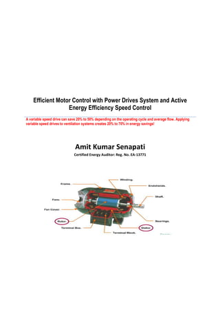
1. Efficient Motor Control with Power Drives System and Active
Energy Efficiency Speed Control
A variable speed drive can save 20% to 50% depending on the operating cycle and average flow. Applying
variable speed drives to ventilation systems creates 20% to 70% in energy savings!
Amit Kumar Senapati
Certified Energy Auditor: Reg. No. EA-13771
2. Efficient Motor Control with Power Drives System and Active Energy Efficiency Speed Control
Purpose of the document: - Understand Efficient Motor Control with Power Drives Systems and improving
know how on opportunities in energy saving by effective speed control.
Power Drive Systen(PDS)
Some of the major components of Power Drive System are as follows:-
a) First, it includes the motor and its sensors. The purpose of the motor is to transform energy into mechanical
power.
b) The gear, or transmission, conveys that power from the motor, to the machine that is performing the work.
c) The variable speed drive module controls the speed of the motor and supports smooth startup.
There is a huge potential for energy savings by looking at the following facts in motors:-
a) Motors Oversizing.
b) Low maintenance and no speed control.
c) Inefficient or poorly maintained power drive system.
An efficient system uses less than half the energy to do the same work
3. On average 97% of the life cycle cost of purchasing and operating a motor is energy related. Still the only factor
considered when selecting a motor is the initial purchase prise.
Reducing the consumption of a motor by 10% can save enough to buy three more motors.
So, the resons to have a power drve system is as follows:-
i) Motors consume a high proportion of total energy(60% - 70% of industrial use)
ii) A lot of motors are oversized and inefficiently controlled.
iii) 97% of the cost of ownership is energy, hence the focus should be more on operating cost rather can
initial purchase.
Less than 5% of the motors are DC motors.
Disadvantages of DC Motors:-
i) The manufacturing and maintenance cost is high.
ii) They require DC supply.
Advantages of DC motors: -
i) The motors are easy to control in speed and have very good performance in torque and speed precision.
Permanent Magnet Motors
A small subset of motors is permanent magnet synchronous motor. Here the rotor is fitted with rare earth magnet in
order to achieve increased field strength in a small volume. Due to their cost they are reserved for high performance
applications(like fast cycle machines). But as the energy consumption is less than indusction motors, they come up
more in applications like lifts.
4. Asynchronous Motors
Asynchronous motors are the most commonly used motor today.
Advantages of Asynchronous motors:-
i) They are very simple, robust and low cost.
Disadvantages of Asynchronous motors:-
i) They have high starting current(5 to 7 times the rated load)
ii) Uncontrolled acceleration.
iii) Their speed decreases slightly with load-This is called, “Slip”.
Basic Principle of Asynchronous Motor
The stator is equipped with three-phase windings, positioned at 120 degree intervals.
5. As the elctrical current rises and falls in each of the phases, a rotating magnetic field is created. This field causes
electric currents in the rotor. Electromagnetic interactions, between the rotor currents and the rotaing magnetic field
creates torque, causing the rotor to run. This then rotates the motor shaft.
The rotor follows the rotating field but rotates a little bit slower.This is referred to as “slip” between the stator rotating
field and the rotor. This slip generates the torque which moves the rotor. The slip also increases the torque. This
means that the speed of an asynchronous motor decreases slightly with load.
Asynchronous Motor : Squirrel Cage Type
The most common and most cost effective motor technology is the so called “Squirrel- cage motor”.
Depending on the supply voltage, the winding can be connected in different ways:-
i) Star coupling : One end of the stator coils are linked to a common node and the other ends to one of
the phases of the power supply.
ii) The windings are connected to form a triangle and each corner is connected to a phase of the
supply, there is no common node.
The squirrel cage rotor is comprised of metal bars short-circuited at their extremities by conducting rings.
Energy Efficiency in Motors
A motors maximum efficiency is obtained at 60%to 100% of full load.Most ofter electric motors are oversized.Motor
applications oversize the mtor because the motor because they are not very concerned about energy efficiency.They
want to ensure that there is no chance of the motor being overloaded. When energy is cheap, this approach is a low
cost trade off against overload risk.But as energy costs rise, the oversizing rapidly becomes wasteful and expensive
answer to this design issue.
6. Motors of a higher efficiency class are more complex to design and produce, and contain more metal, different
metals, or high grade metals to provide conductors with lower losses.The motor price will increase accordingly. In
relation to the motor lifetime the purchase proce is only a few percentage points and, due to the saved energy cost,
the pay back period is short.
Motor Efficiency
Electrical motor efficiency (η) is the ratio between the mechanical shaft output power and the electrical input power.
Internal losses include electrical, mechanical, and magnetic losses.
Electric input power can be determoined by input voltage, current and power factor of the motor.
Electric output power is equal to square root of three multiplied by the three phase volatge, current and power factor.
Rewinding motors generally cost about 60% of the cost to replace them. Efficiency drops when motors are rewound.
The best policy is to rewind highly efficient motors and to sell or salvage those that are not.
Gear Purpose
The output speed can be controlled very simply in the following manner. If the input gear with 20 teeth rotates at 10
revolutions per minute (rpm) and it’s connected to an output gear containing 100 teeth, that output gear will rotate at
2 revolutions per minute. The gear ratio in this example is 100:20 or 5:1.
Active Energy Efficiency Using Speed Control
An estimated 60% of motors are not speed controlled.
Many types of equipment can benefit from proper speed control – from pumps and fans to compressors and
machines.
Some of the Affinity rules are as follows: -
Flow is the output from a device such as a fan, pump or compressor, expressed in cubic meters per second or cubic
feet per minute. It is proportional to the shaft speed of the motor. This means that
i) With half the Shaft speed, we get half the flow.
ii) Pressure is proportional to the shaft speed, squared. So with half the shaft speed, you get a quarter of
the pressure.
iii) Power is proportional to the shaft speed, cubed.
7. Variable Speed Drives
i) Variable speed drive is more efficient. With variable speed drives, starting and stopping operations are
made smooth and perfectly controlled.
ii) Slow starting also minimizes inrush currents that often accompany a motor sudden starting. Inrush
currents cause voltage sags that can have damaging effects on the motor and other affected equipment.
iii) Variable speed drives is sometimes called variable frequency drive. This is because the drive receives AC
power at a constant frequency, such as 50 or 60 Hz, and converts it into a variable frequency for supply to
the motor.
Three options associated with starting a motor are as follows:-
i) Direct On Line
Direct On Line starting connects the motor stator windings directly to the main supply. The motor will start
and accelerate according to its natural characteristics.
The starting method is suitable for stable supplies, mechanical still and well designed shaft system.
The starting equipment consists of a main contactor – effectively an on/off switch which is suitable for the
required current – and a thermal or electronic overload relay.
The disadvantage of a direct-on-line starter is the high inrush current that occurs when the motor starts
turning.It may draw a current that is 5 to 7 times the nominal current until it is up to full speed. The inrush
currents can generate mechanical shocks that warrant oversized wiring and additional surge protection.
8. ii) Star Delta
This method requires 3 contactors and a control part to manage the contractor sequence. Both ends of the
motor windings must be accessible. The motor windings are connected in star formation upon starting.
Once the motor torque matches the load torque, the winding connection is changed to delta connection.
9. Star/delta provides a softer start than DOL but acceleration is still not controlled. Star/delta is always used
for motors above 10kW to preserve and optimize the electric installation and mechanical parts.The motor
is started with the Y(Star) connection and accelerated as far as possible, then switched to D(Delta)
connection.Star/Delta connection causes the starting current of about one third the current associated with
DOL starting.The rupture in the star/delta starting current is the result of the starting current making the
switch between star and delta.
iii) Soft Starting
Soft starters increase voltage gradually to generate a smooth, steady acceleration and are perfectly
compatible with DOL and star/delta motors. Although a soft starter does smoothly and gently start a motor,
and bring it up to full speed in a controlled manner, it does not provide substantial energy savings or
variable speed control. During the starting process, the soft starter progressively increases the motor
voltage so that the motor becomes strong enough to accelerate the load to rated speed without causing
torque or current peaks. Soft Starters can also be used to control the stopping of a process and provide
thermal and short circuit protection for the motor.
Direct starting methods are inexpensive, but their performance is also not upto mark.
DOL and star/delta starting methodologies can be stressful on mechanical parts and gear trains. They also
draw high inrush currents.
The soft starter preserves the efficiency of gear trains and mechanical parts, but does nothing to master
speed or torque, which are the main factors to control in a process to make significant energy savings.
The variable speed drive is also known as a frequency converter and is known for having every accurate
speed and torque regulation. It has a rectifier bridge followed by the inverter. Both allow voltage amplitude
and frequency to be varied.
10. Variable speed drives allow electrical and mechanical equipment to be down sized by limiting the starting
current.
11. The same is true for ventilation systems. In fact, using speed drives in fan installations brings 20% to 70% in
energy savings. Notice the power consumption versus air flow curve in this fan installation. The blue line is
the power versus air flow curve when the air flow is controlled with an outlet damper. The red line is the
power versus air flow curve when the air flow is controlled with an inlet vane.
The green line shows the power drawn by removing or fully opening the damper and controlling the speed.
Using an output damper to reduce the flow to 80% uses 95% of the motor’s power. Using an inlet vane to
reduce the flow to 80% still uses 70% of the motor’s power. And using a speed drive uses only 50% of the
12. motor’s power.
One of the major disadvantage of Frequency Converter is that they generate harmonic distortion in the power
network.
Harmonic currents and voltages are generated by non-linear loads connected to the power distribution system.
C-less drive technology uses a frequency converter with very low capacitance value on the DC supply. This
isbecause capacitance is the main source of dictortion. However reducing the capacitance also reduces the
performance of the motor control, which makes it suitable for applications such as HVAC where high performance
speed drives are not required. THDI can be reduced to 30%.
A 12 pulses system is a type of drive design that uses 2 rectifier bridges to supply the DC bus. Each rectifier
is supplied by a secondary winding of a specific transformer; each secondary has a de-phasing of 30°. The
result on the other side is an attenuation of the 5th and 7th orders of harmonics.
An 18 pulses drives involves the same principal but with 3 rectifier bridges.
There are two main types of active filters. First is the Active Front End (AFE). Here the classical rectifier
bridge is replaced by an inverter controlled in order to draw a sinusoidal current onto the network.
A line active filter is a device installed on the power distribution network that senses harmonics and injects,
in opposite phase, a balancing harmonic to maintain a sinusoidal line current. They are very effective but
can be expensive. They are normally used above 100kW and can reduce THDi to under 5%.
A variable speed drive can save 20% to 50% depending on the operating cycle and average flow. Applying variable
speed drives to ventilation systems creates 20% to 70% in energy savings!
References:
1. How to make money by Energy Auditing. Author. Balasubhraminiam.
2. Schneider Energy University.