The document discusses an energy-efficient RF remote control system for dimming household appliances, utilizing a Zigbee module for wireless communication over a range of 100 meters. This system offers enhanced usability and reduction in power consumption compared to traditional IR remotes by allowing multiple appliances to be controlled simultaneously. It emphasizes the importance of energy savings through adjustable dimming capabilities for various applications, including public lighting and home use.
![TELKOMNIKA Indonesian Journal of Electrical Engineering
Vol. 13, No. 2, February 2015, pp. 232 ~ 237
DOI: 10.11591/telkomnika.v13i2.7046 232
Received November 20, 2014; Revised January 2, 2015; Accepted January 15, 2015
Energy Efficient RF Remote Control for Dimming the
Household Applainces
Rajesh Singh*, Piyush Kuchhal, Anita, Sushaban Choudhary
University of Petroleum and Energy Studies, Dehradun, India
*Corresponding author, e-mail: rsingh@ddn.upes.ac.in
Abstract
During recent years there is a strong trend towards radio frequency (RF) remote controls as it is
delivering even more comfort to the users and increased usability with high robustness of the RF links.
Lower power consumption with new features and security make RF remote control systems more
competitive with widely used IR remote control systems. In this paper we propose, a RF module based
real time system, which is an integrated system designed to control the dimming or speed of the
appliances. Zigbee module is used as RF module to establish wireless link between Remote and appliance
section having 9600kbs baud rate and range of 100m. Dimming control circuits is part of appliances
section which is used to control the appliances corresponding to signals generated by the remote section.
This system provides energy efficient solution for household uses.
Keywords: applaince section, dimming control circuit, energy efficient, RF remote
Copyright © 2015 Institute of Advanced Engineering and Science. All rights reserved.
1. Introduction
In present market there are number of IR remote controlled appliances are available.
The data transmission using IR modules are having limitation of line of sight, which is required
by transmitter and receiver. In this paper, an energy efficient systems under dimming condition
is considered, paper focus on system cost, real energy saving, reliability and environmental
friendliness. The system proposed for large-scale lighting applications where the dimming
function can be used to provide energy savings such as car parking, residential public parks etc
[1]. The system provides solution to existing wired lightning system having complex construction
[2]. The energy consumption is rapidly increasing due to development of the urbanization
process and population. It also affects the cost and supply of electricity [3]. Due to drawback of
its short range and speed RS-232-based digitally dimming lighting system and also each lighting
area needs its own driver and dimmer circuit, which results in large numbers of circuit
components and non-cost-effectiveness. It needs to improve [4]. USB-based protocol instead of
the RS-232-based, provide better interface and increase dimming controlled nodes (devices)
with the use of Zigbee transmission [5]. Zigbee transreceiver module is based on IEEE 802.15.4
protocol to make the wireless sensor network [6]. The system provides the characteristics of low
power, low cost, flexible structure [7]. ADPCM (adaptive differential pulse code modulation)
dimming control system can be used to control the LED current with high resolution. It also
helps to reduce RFI (radio frequency intensity) because of spreading out the harmonic current
of pulses [8]. By simulation results it can be concluded that pulse width modulation (PWM)-
based pulse position modulation (PPM) signal format is better for visible light communication
systems. It is also useful for operation of data transmission and dimming control simultaneously
[9]. A new scheme is proposed to avoid problems of the pulse width modulation (PWM) control
of the lamp current. A PWM-controlled half-bridge inverter is used for this purpose [10]. A
dynamic dimming control system is discussed for highway tunnel LED lighting, based on
controllability of LED [11].
2. Hardware Development
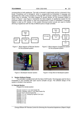
In the proposed system the communication range between remote and appaliance node
is of 100 meters. At the remote section control switches (two for UP/DOWN dimming bulb, two
for UP/DOWN dimming Fan and One for OK the set level ) are to generate control signals](https://image.slidesharecdn.com/0518nov147046-14819-1-smedit-171214012543/85/Energy-Efficient-RF-Remote-Control-for-Dimming-the-Household-Applainces-1-320.jpg)
![TELKOMNIKA Indonesian Journal of Electrical Engineering
Vol. 13, No. 2, February 2015, pp. 232 ~ 237
DOI: 10.11591/telkomnika.v13i2.7046 232
Received November 20, 2014; Revised January 2, 2015; Accepted January 15, 2015
Energy Efficient RF Remote Control for Dimming the
Household Applainces
Rajesh Singh*, Piyush Kuchhal, Anita, Sushaban Choudhary
University of Petroleum and Energy Studies, Dehradun, India
*Corresponding author, e-mail: rsingh@ddn.upes.ac.in
Abstract
During recent years there is a strong trend towards radio frequency (RF) remote controls as it is
delivering even more comfort to the users and increased usability with high robustness of the RF links.
Lower power consumption with new features and security make RF remote control systems more
competitive with widely used IR remote control systems. In this paper we propose, a RF module based
real time system, which is an integrated system designed to control the dimming or speed of the
appliances. Zigbee module is used as RF module to establish wireless link between Remote and appliance
section having 9600kbs baud rate and range of 100m. Dimming control circuits is part of appliances
section which is used to control the appliances corresponding to signals generated by the remote section.
This system provides energy efficient solution for household uses.
Keywords: applaince section, dimming control circuit, energy efficient, RF remote
Copyright © 2015 Institute of Advanced Engineering and Science. All rights reserved.
1. Introduction
In present market there are number of IR remote controlled appliances are available.
The data transmission using IR modules are having limitation of line of sight, which is required
by transmitter and receiver. In this paper, an energy efficient systems under dimming condition
is considered, paper focus on system cost, real energy saving, reliability and environmental
friendliness. The system proposed for large-scale lighting applications where the dimming
function can be used to provide energy savings such as car parking, residential public parks etc
[1]. The system provides solution to existing wired lightning system having complex construction
[2]. The energy consumption is rapidly increasing due to development of the urbanization
process and population. It also affects the cost and supply of electricity [3]. Due to drawback of
its short range and speed RS-232-based digitally dimming lighting system and also each lighting
area needs its own driver and dimmer circuit, which results in large numbers of circuit
components and non-cost-effectiveness. It needs to improve [4]. USB-based protocol instead of
the RS-232-based, provide better interface and increase dimming controlled nodes (devices)
with the use of Zigbee transmission [5]. Zigbee transreceiver module is based on IEEE 802.15.4
protocol to make the wireless sensor network [6]. The system provides the characteristics of low
power, low cost, flexible structure [7]. ADPCM (adaptive differential pulse code modulation)
dimming control system can be used to control the LED current with high resolution. It also
helps to reduce RFI (radio frequency intensity) because of spreading out the harmonic current
of pulses [8]. By simulation results it can be concluded that pulse width modulation (PWM)-
based pulse position modulation (PPM) signal format is better for visible light communication
systems. It is also useful for operation of data transmission and dimming control simultaneously
[9]. A new scheme is proposed to avoid problems of the pulse width modulation (PWM) control
of the lamp current. A PWM-controlled half-bridge inverter is used for this purpose [10]. A
dynamic dimming control system is discussed for highway tunnel LED lighting, based on
controllability of LED [11].
2. Hardware Development
In the proposed system the communication range between remote and appaliance node
is of 100 meters. At the remote section control switches (two for UP/DOWN dimming bulb, two
for UP/DOWN dimming Fan and One for OK the set level ) are to generate control signals](https://image.slidesharecdn.com/0518nov147046-14819-1-smedit-171214012543/75/Energy-Efficient-RF-Remote-Control-for-Dimming-the-Household-Applainces-1-2048.jpg)
![ ISSN: 2302-4046
TELKOMNIKA Vol. 13, No. 2, February 2015 : 232 – 237
236
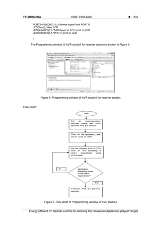
The Table 1 shows the load power consumption w.r.t dimming level of the device with
the help of dimmer circuit, if divided into eight levels.
Table 1. The load power of dimmable port (up to 1kW)
Input to
dimmer
from
controller
% input
provided
by remote
Load
current
(A)
Voltage
across port
(V)
Load
Power
(W)
At 50
ohm
111 15 1.1 55 60.5
110 25 1.88 94 176.74
101 40 2.4 120 288
100 50 2.8 140 392
011 60 3.2 160 512
010 75 4.04 202 816.08
001 85 4.36 218 950.48
000 100 4.6 230 1058
Figure 8 shows the graphical relation of power consumption w.r.t dimmer level. It clearly
shows at low dimmer level power consumption is low.
Figure 8. Graph shows relation between power consumption w.r.t dimmer levels
Black color graph line shows current consumption by system w.r.t dimmer level. Blue
graph line shows voltage required by the system w.r.t dimmer level. Sky blue graph line shows
power consumption by the system w.r.t dimmer level.
4. Conclusion
Zigbee module based developed system has no limitation of line of sight like IR remotes
and establish wireless link at 9600kbps. The number of appliances can be controlled by using
single module of the proposed system. Dimmer control system is able to reduce the amount of
energy. The system offers energy saving through their dimming capabilities and to reduce
electrical demand.
References
[1] Chung HSH, Ngai-Man Ho, Wei Yan, Tam PW, Hui SY. Comparison of Dimmable Electromagnetic
and Electronic Ballast Systems-An Assessment on Energy Efficiency and Lifetime. Industrial
Electronics, IEEE Transactions on. 2007; 54(6): 3145, 3154.
[2] LiLian LiLi. Wireless dimming system for LED Street lamp basedon ZigBee and GPRS System
Science 3rd
International conference on Engineering Design and Manufacturing. Informatization
(ICSEM). 2012; 2: 100-102](https://image.slidesharecdn.com/0518nov147046-14819-1-smedit-171214012543/85/Energy-Efficient-RF-Remote-Control-for-Dimming-the-Household-Applainces-5-320.jpg)
![TELKOMNIKA ISSN: 2302-4046
Energy Efficient RF Remote Control for Dimming the Household Applainces (Rajesh Singh)
237
[3] Fan Chunling, Guo Yuan. The application of a ZigBee based wireless sensor network in the LED
street lamp control system Image. International Conference on Analysis and Signal Processing
(IASP). 2011: 501 – 504.
[4] Cheng Liang L. Implementation of a digitally dimming controlled lighting system for two
area fluorescent lamps. 5th IEEE Conference on Industrial Electronics and Applications (ICIEA).
2010: 2281 – 2286.
[5] Chun An Cheng; Hung-Liang Cheng, Kun-Jheng Lin, Kuan-Lin Chu, Chun-Hsien Yen. A digitally
wireless dimmable lighting system for two-area fluorescent lamps. TENCON 2010 - 2010 IEEE Region
10 Conference. 2010; 2173,2178.
[6] Singh R Mishra, S Joshi P. Pressure Monitoring in wireless sensor network using Zigbee™
transceiver module. ICCCT. 2011 ISBN: 978-1-4577-1385-9.
[7] Singh R, Mishra S. Temperature monitoring in wireless sensor network using Zigbee transceiver
module. Power, Control and Embedded Systems (ICPCES). International Conference on. 2010; 1-4.
[8] Yoo, Sooyeub Yoo, Sooyeub. Highly efficient LED light driver with dimming control using delta sigma
modulation. 31st International Telecommunications Energy Conference. 2009: 1 - 4.
[9] Hyung-Joon Jang, Joon-Ho Choi, Ghassemlooy Z, Chung Ghiu Lee, PWM-based PPM format for
dimming control in visible light communication system. Communication Systems, Networks & Digital
Signal Processing (CSNDSP). 8th International Symposium on. 2012: 1,5.
[10] Raiser F. Dim the lights. Problems with lamp current control using a PWM signal. Industry Applications
Magazine, IEEE. 2002; 8(6): 54,59.
[11] Dingyuan Wang, Haifeng Jiang, Junfeng Ma, Xiaolong Zheng. Dynamic Dimming Control Method
Research on Tunnel LED Lighting Based on LED Controllability. Remote Sensing, Environment and
Transportation Engineering (RSETE). 2nd International Conference on. 2012: 1,4.](https://image.slidesharecdn.com/0518nov147046-14819-1-smedit-171214012543/85/Energy-Efficient-RF-Remote-Control-for-Dimming-the-Household-Applainces-6-320.jpg)