Download as PDF, PPTX
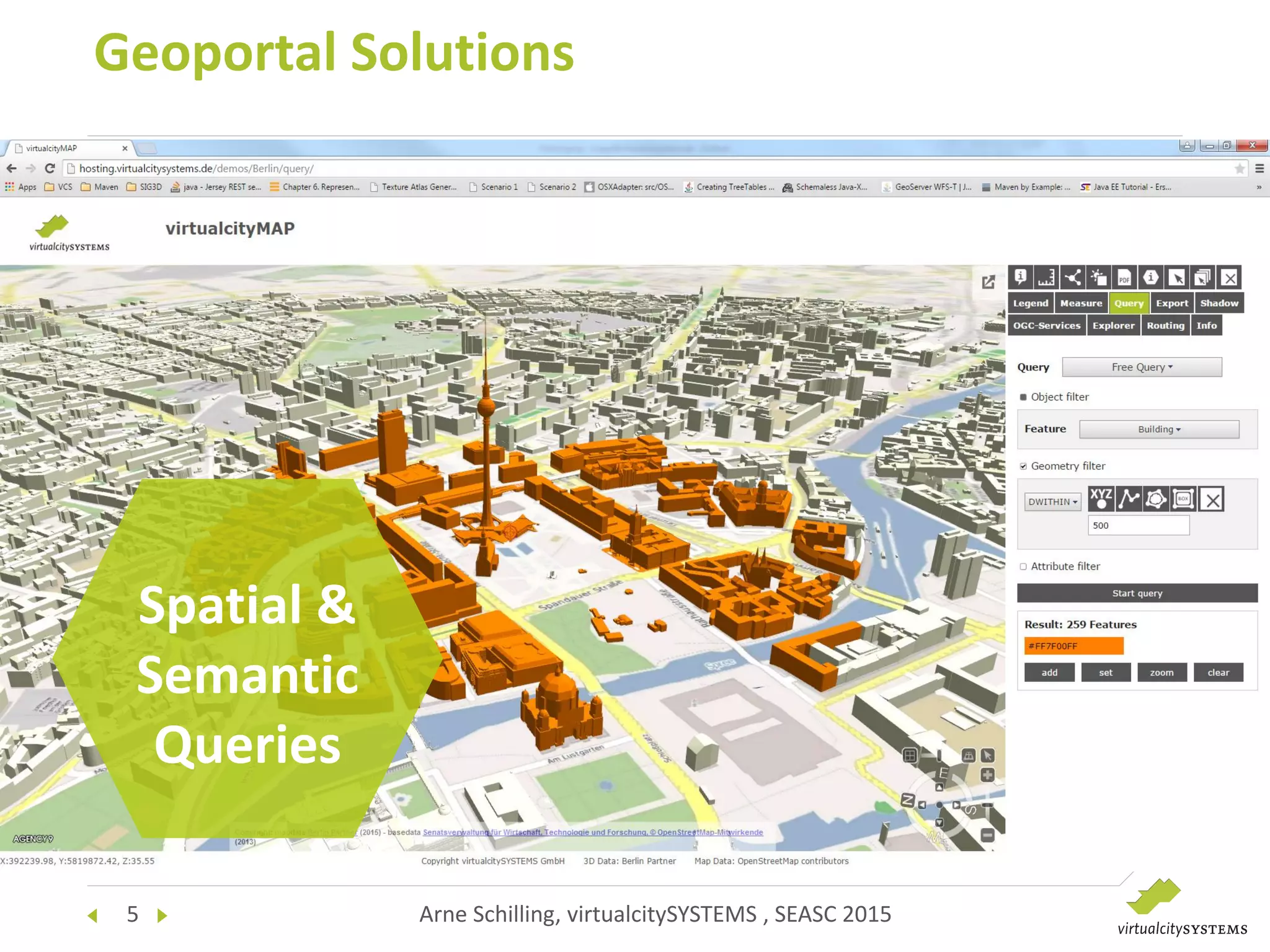
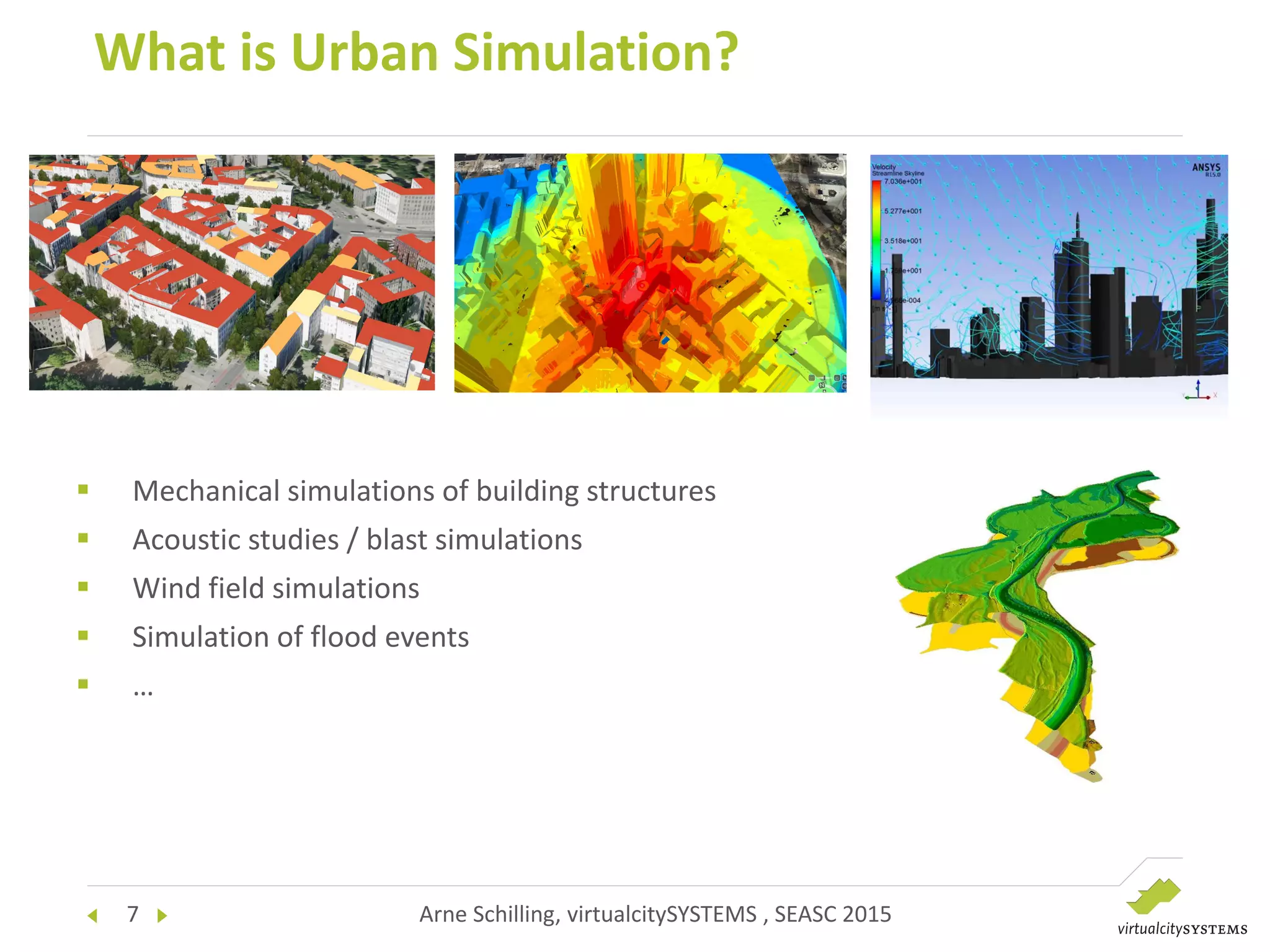
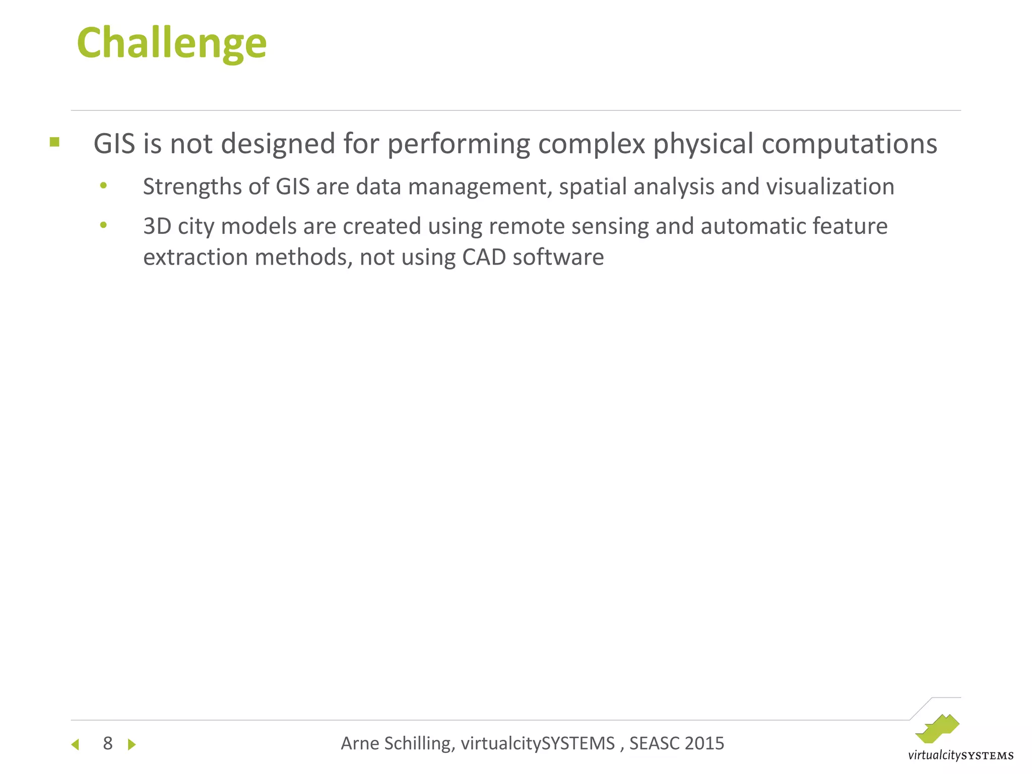
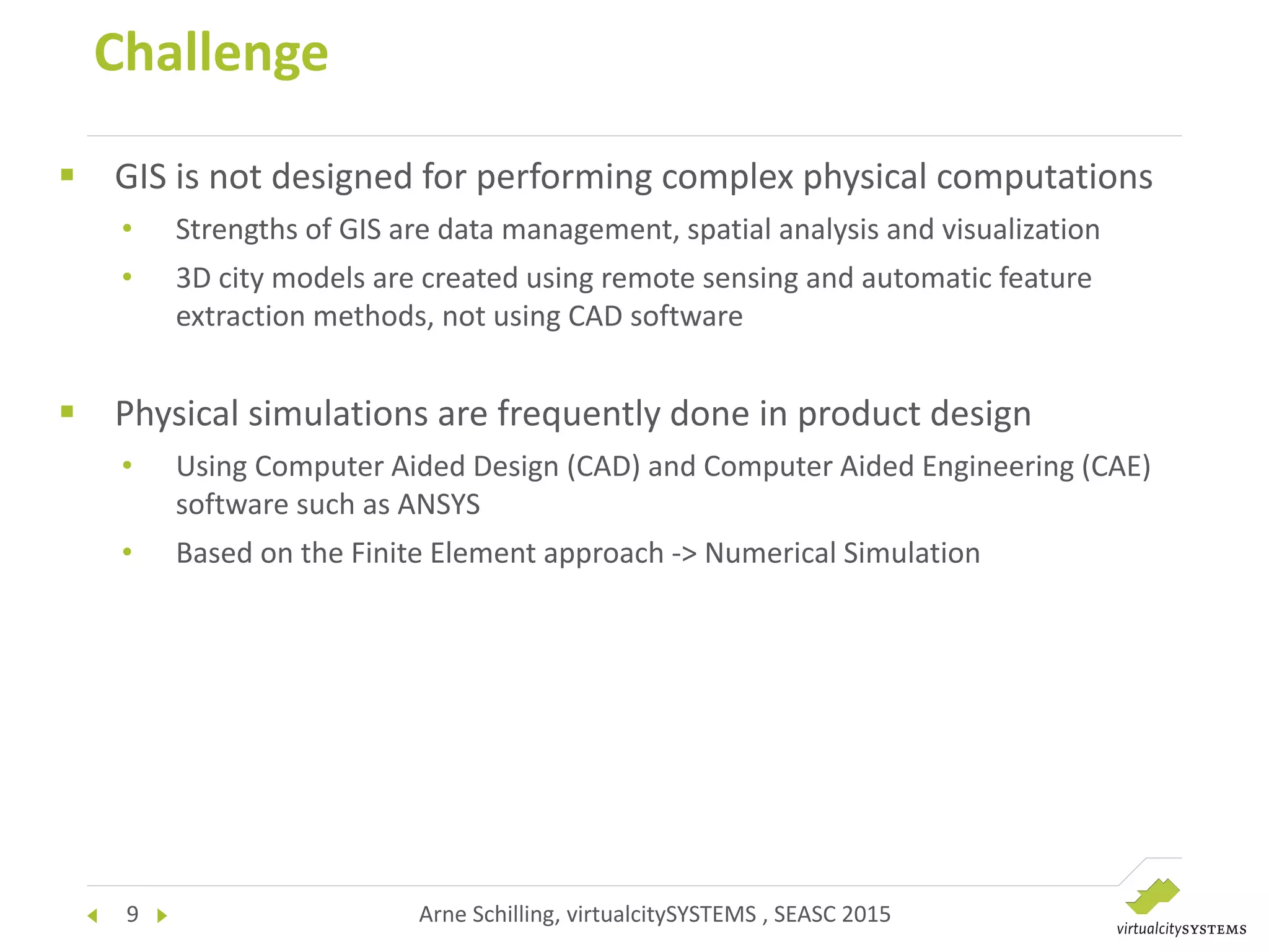
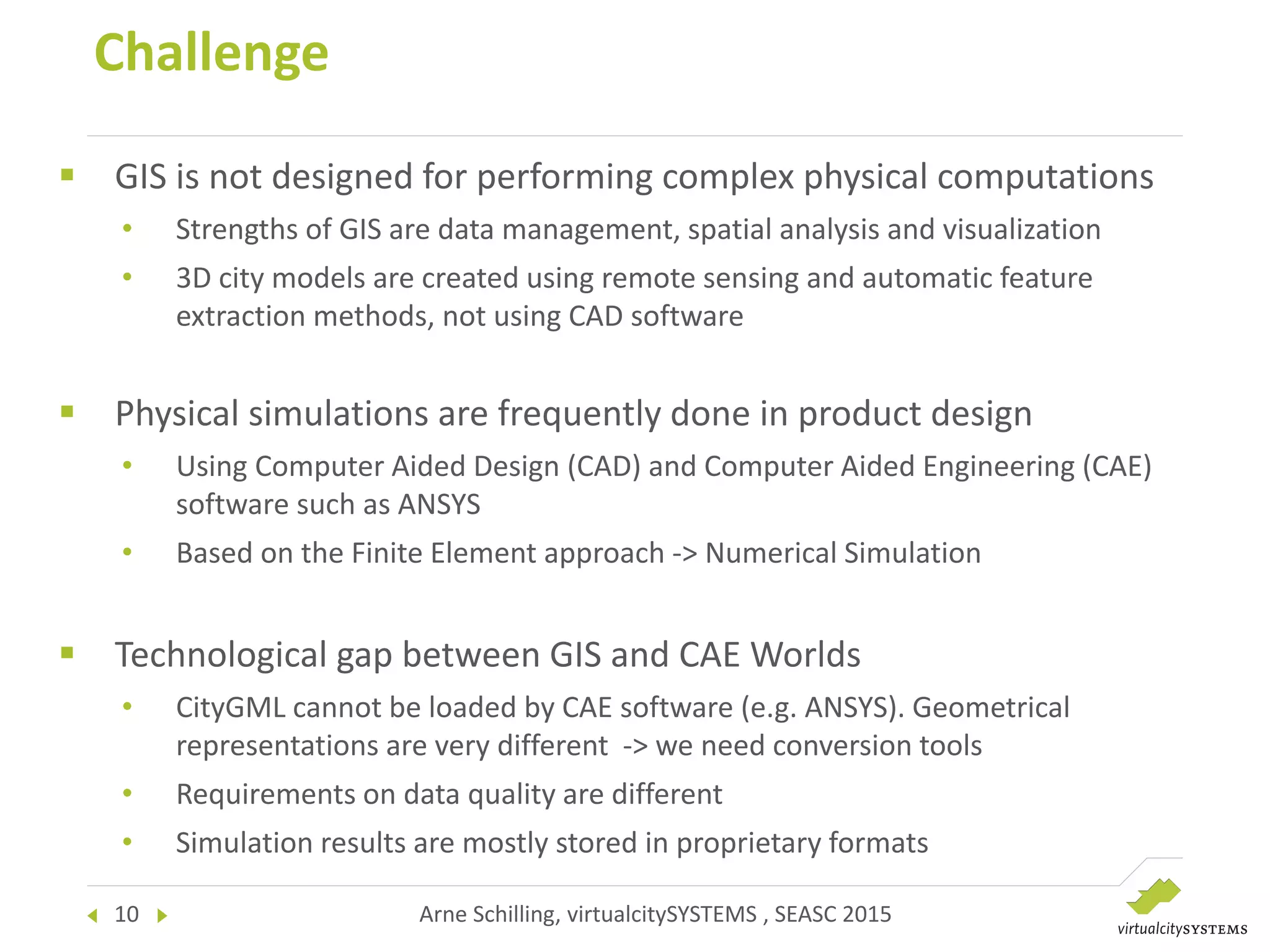
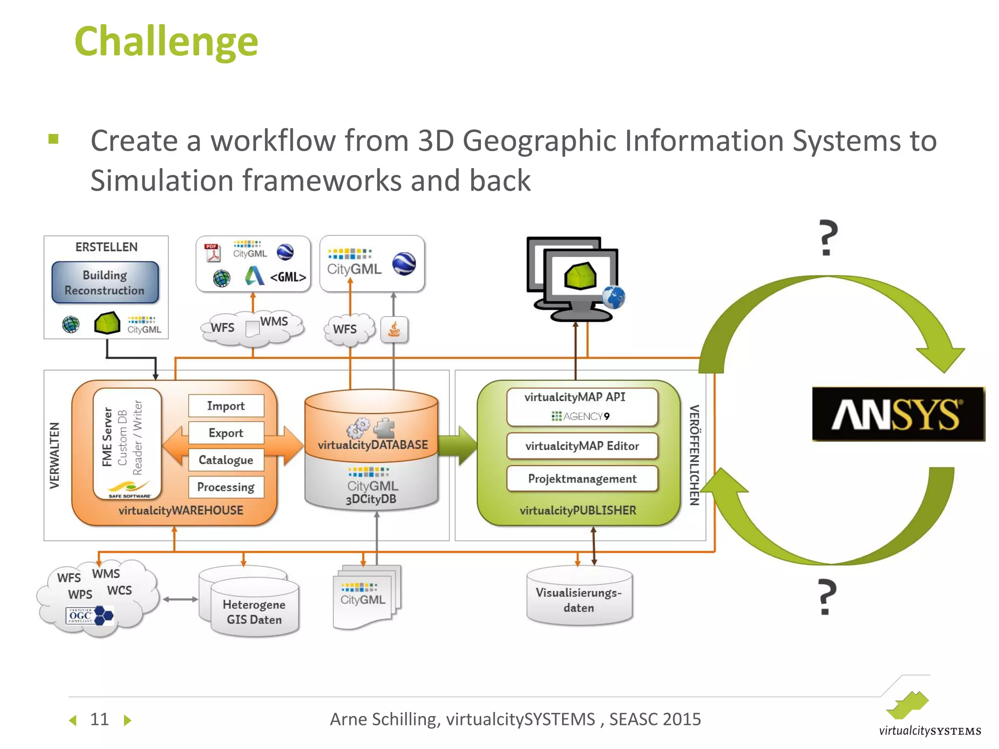
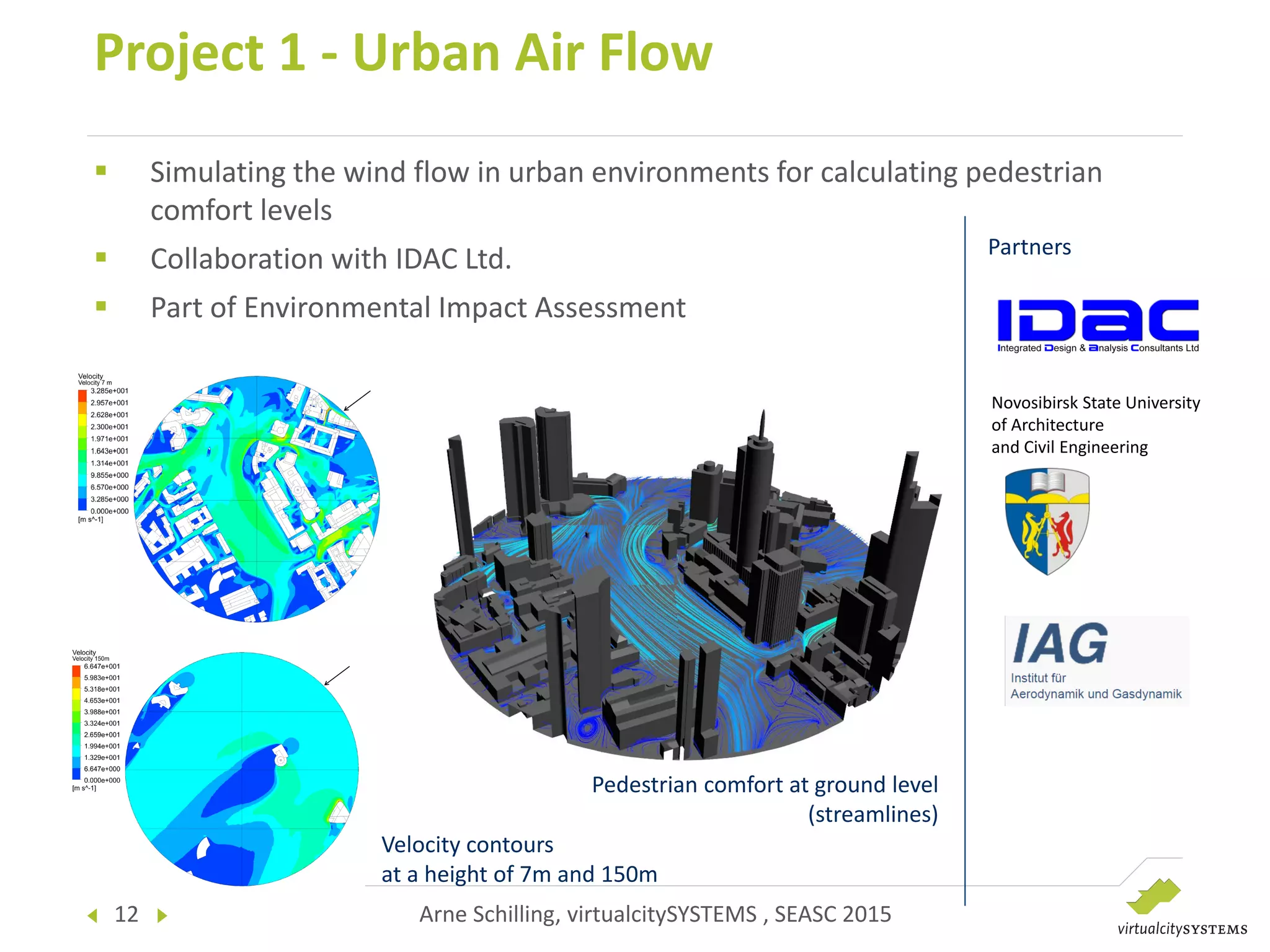
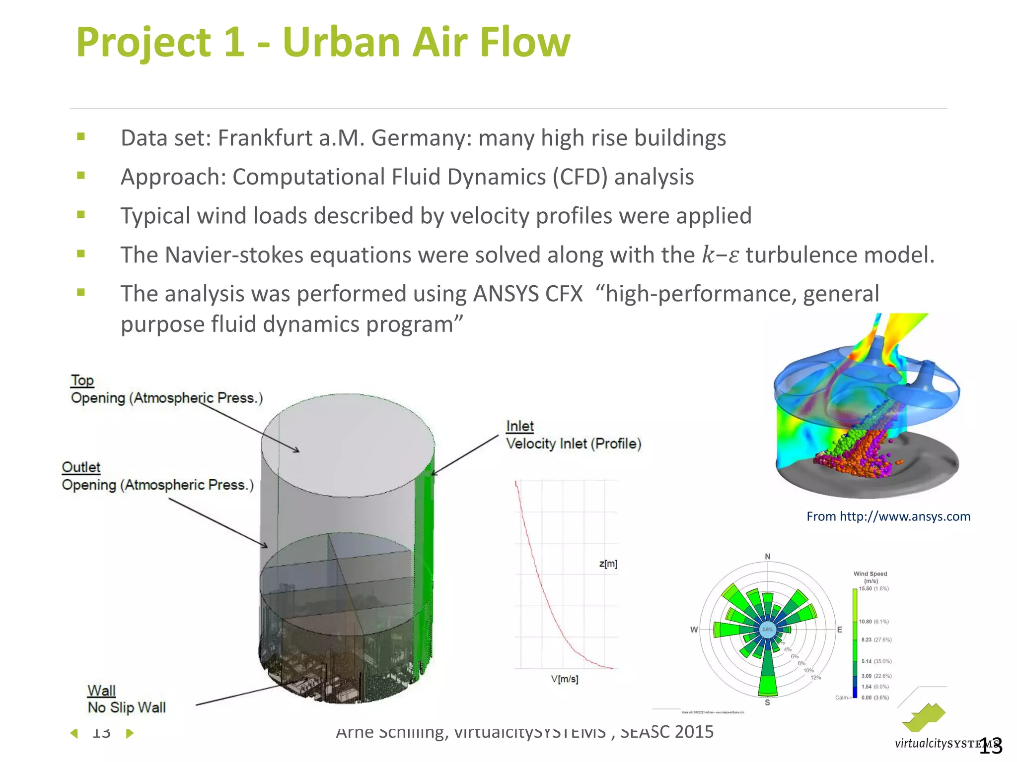
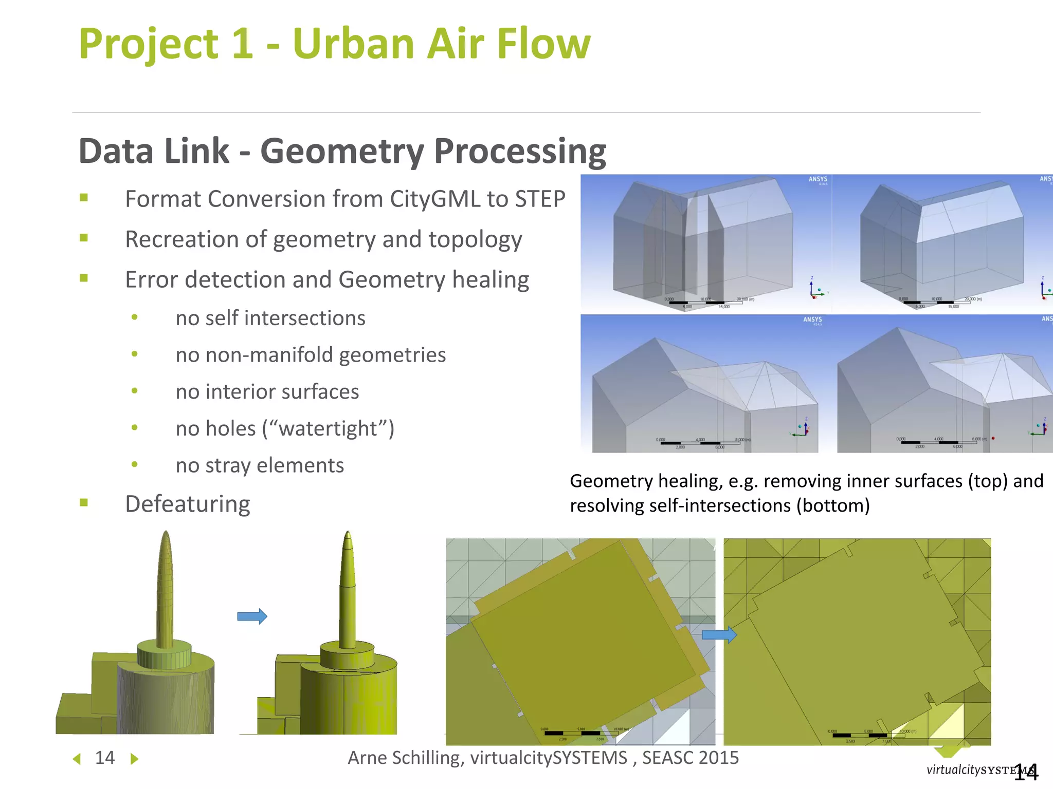
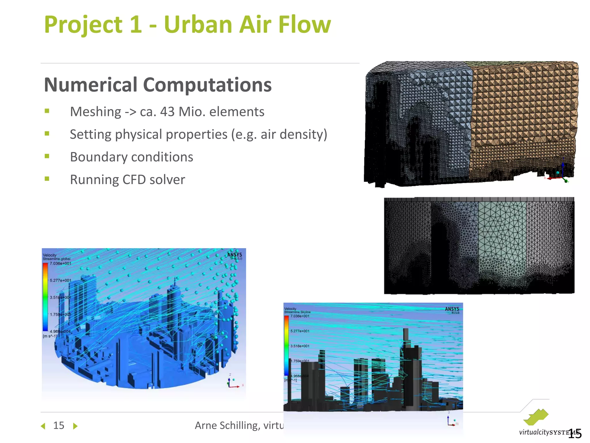
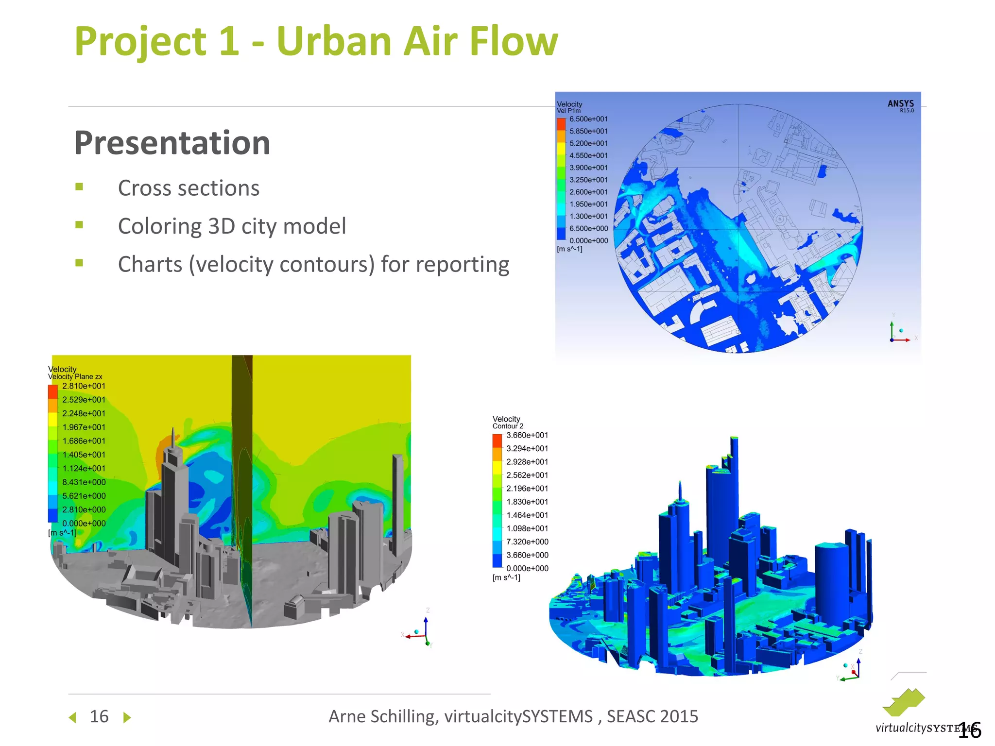
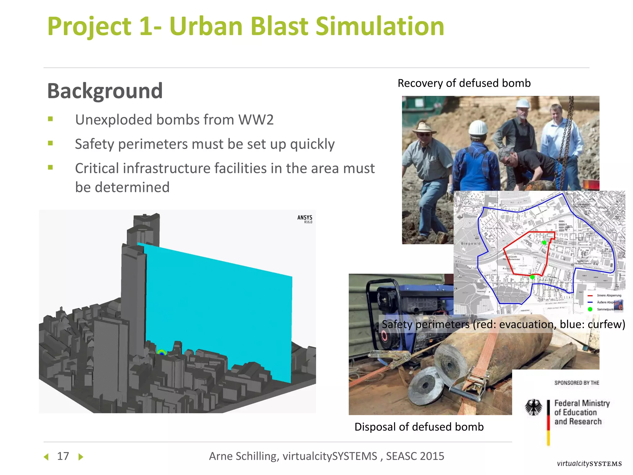
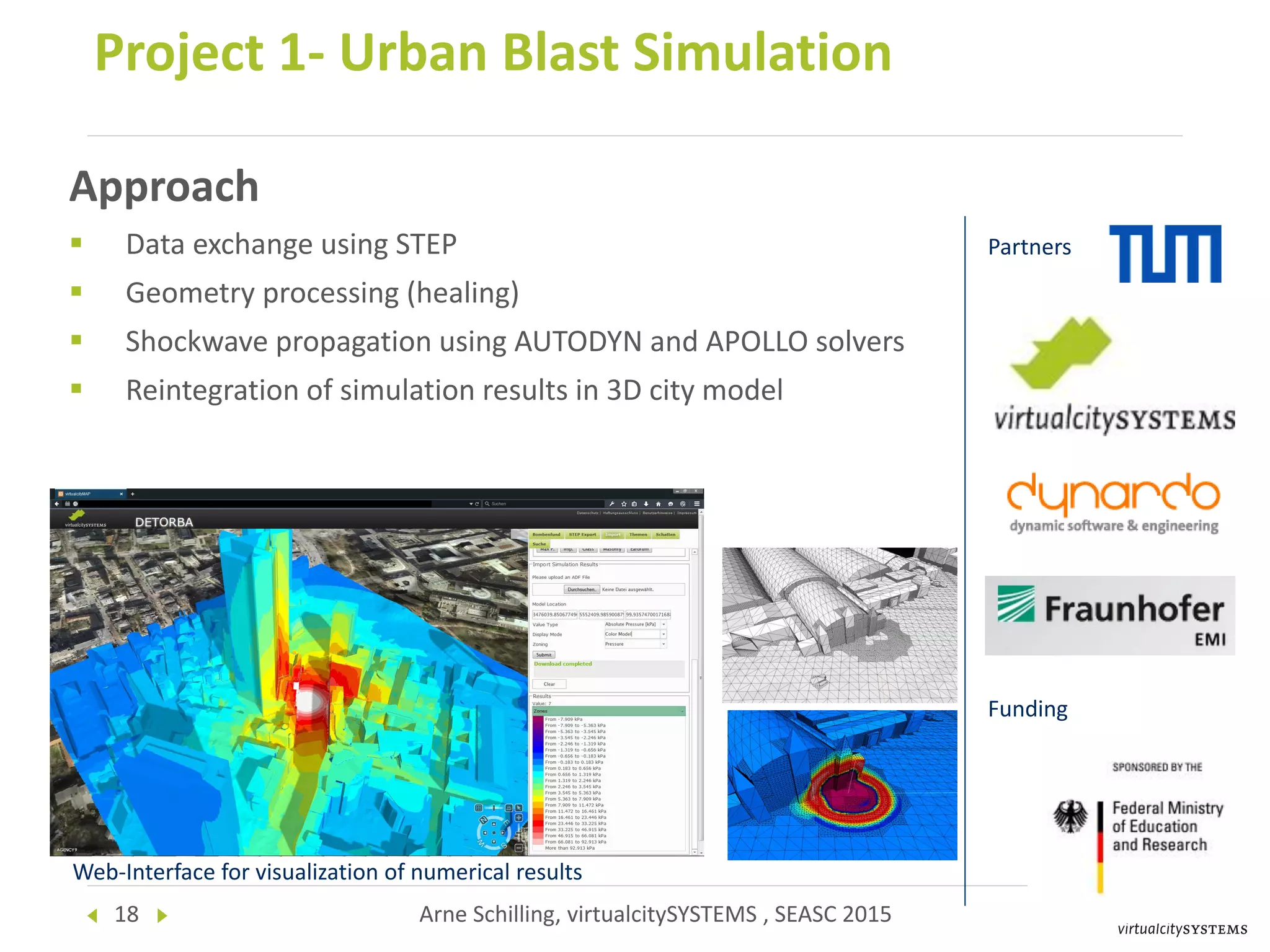
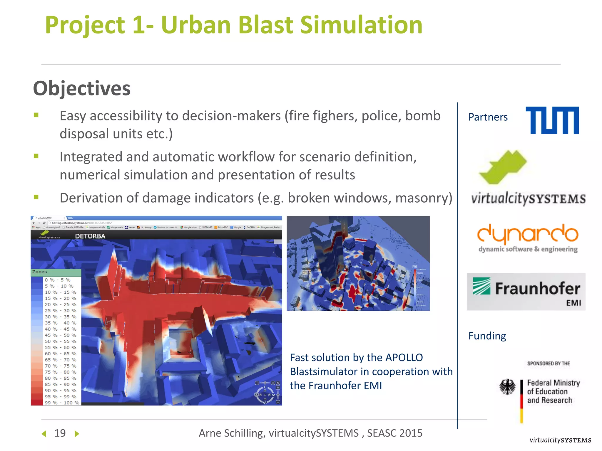
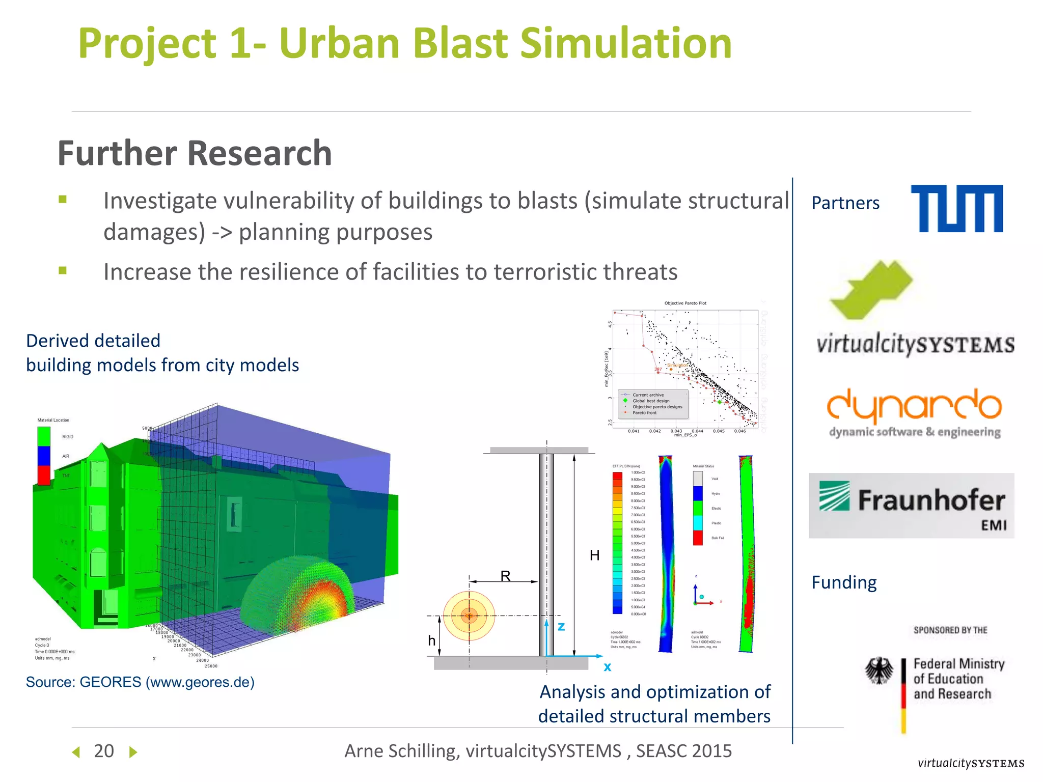
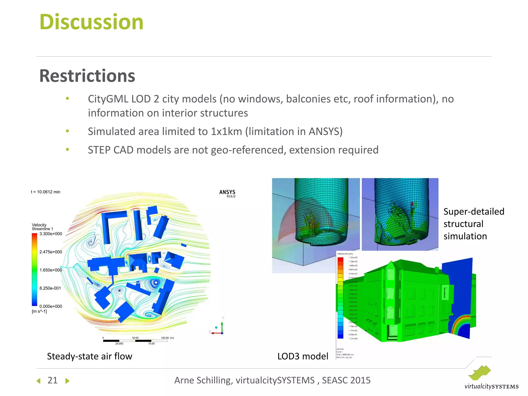
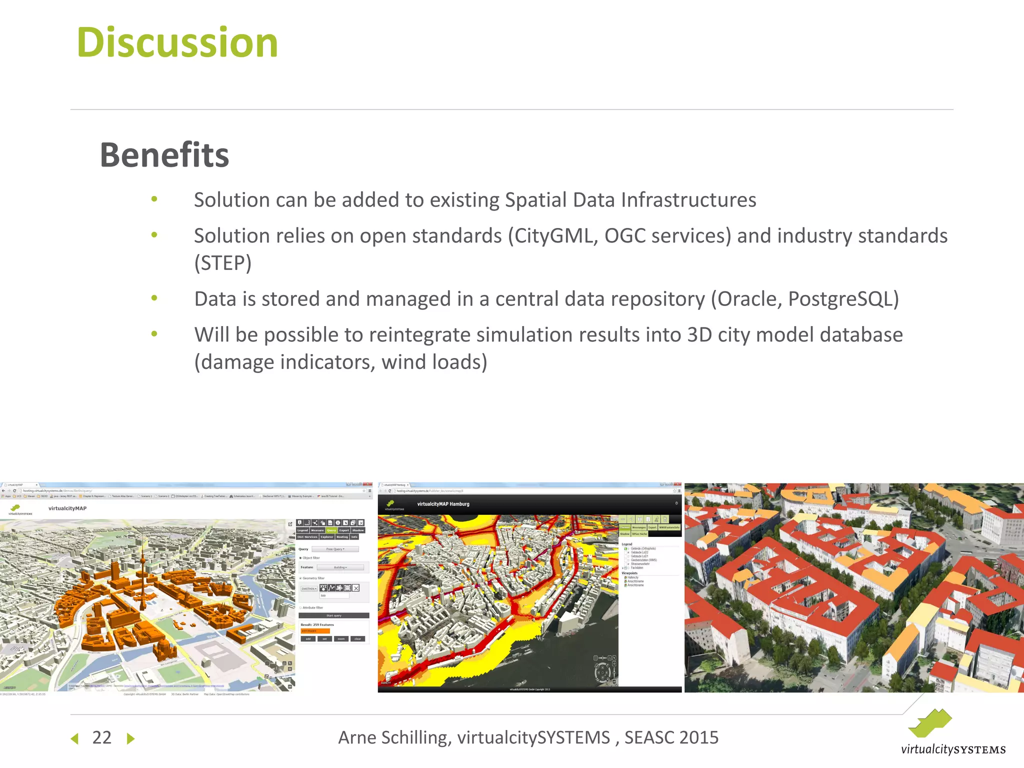
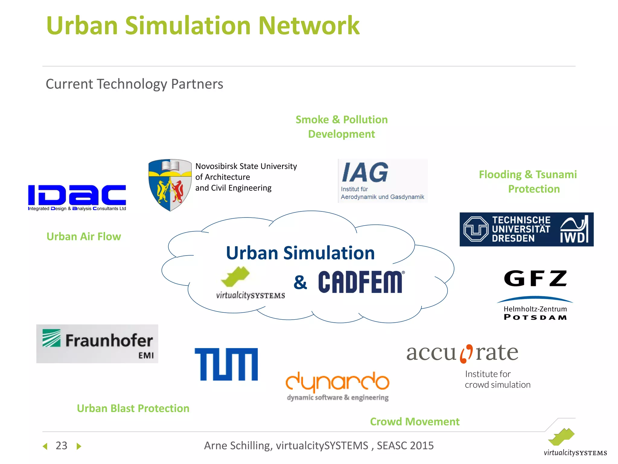
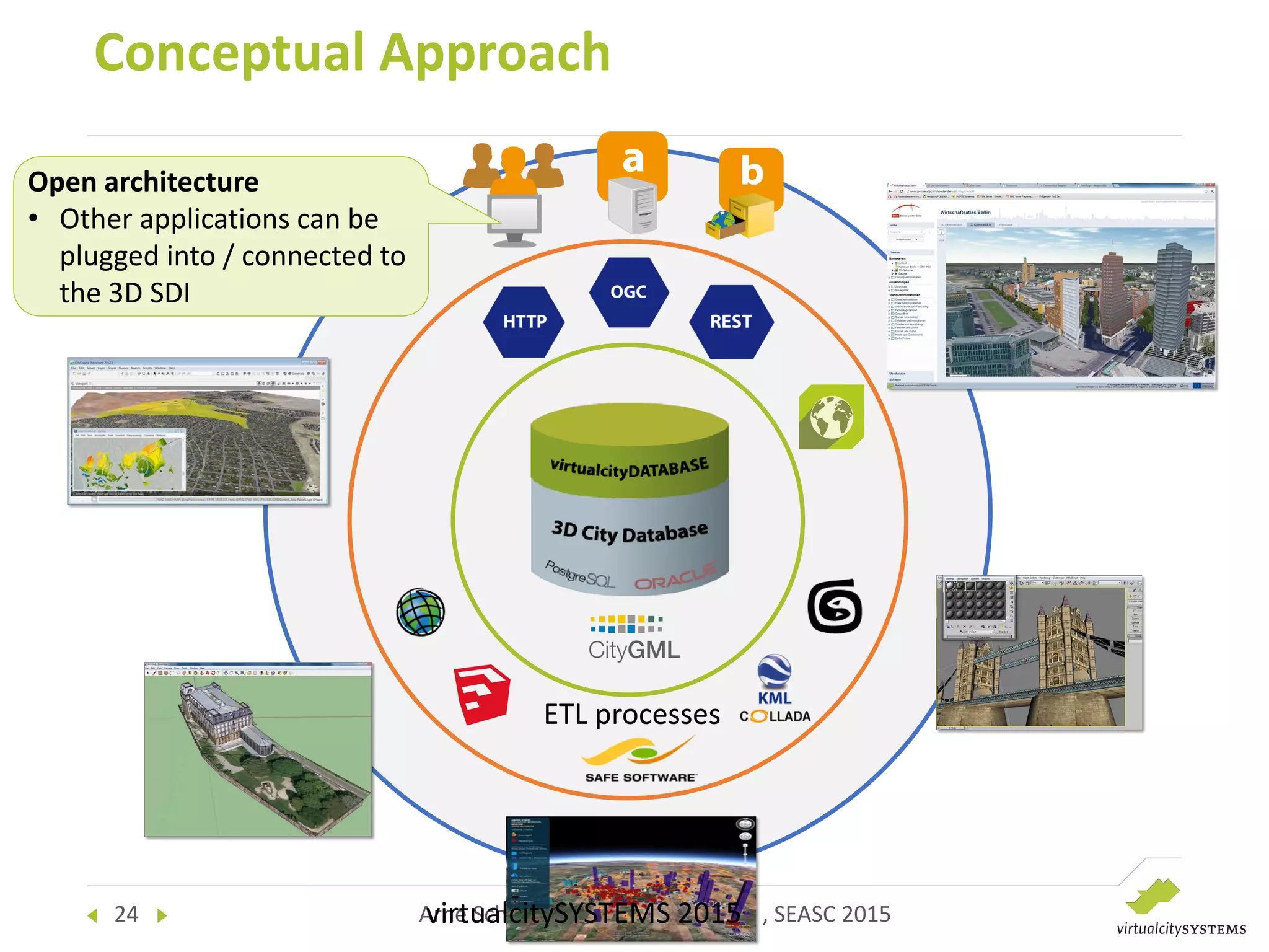
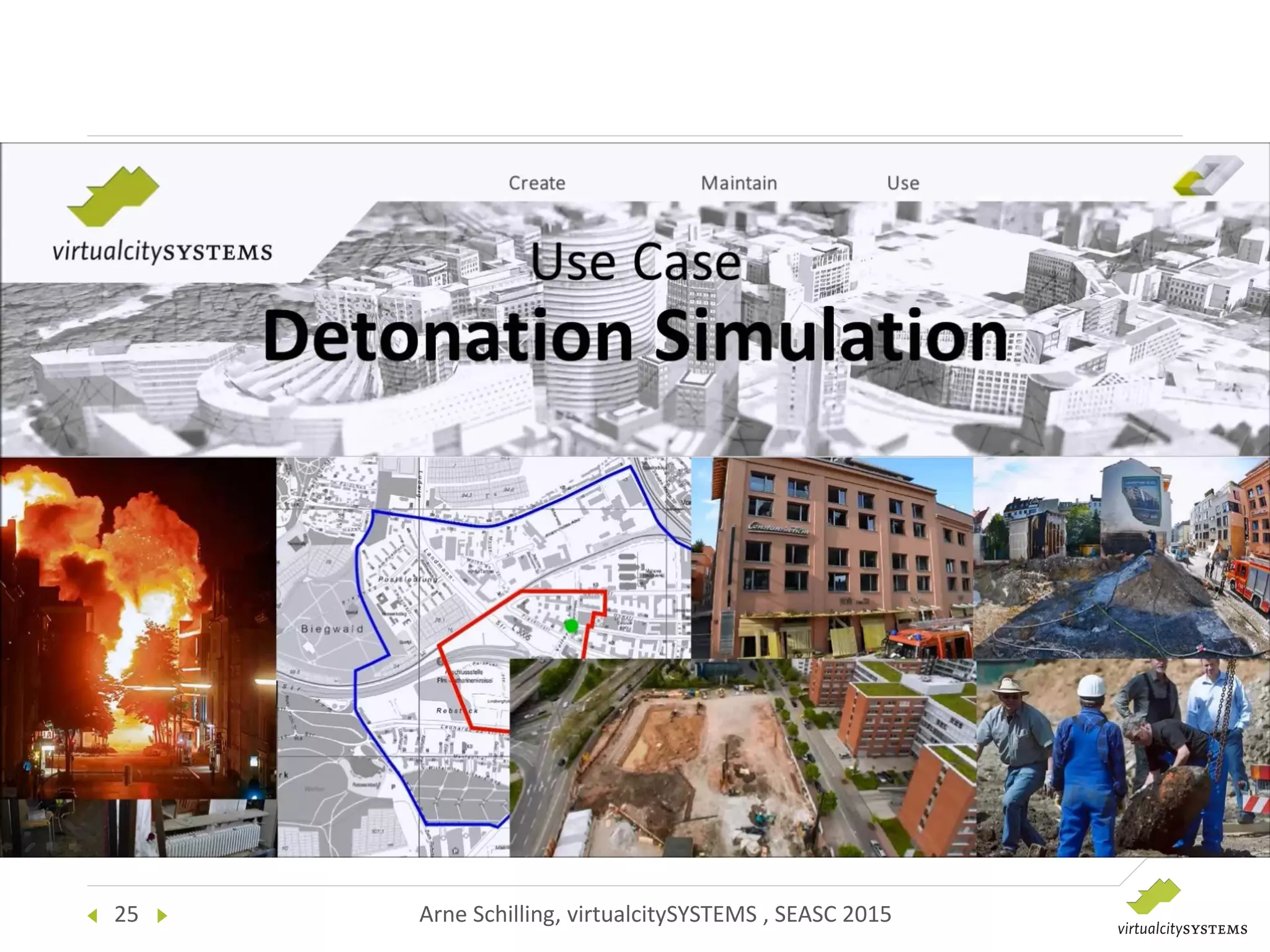


This document discusses enabling numerical simulations in 3D city models using CityGML. It describes two projects: 1) Simulating urban air flow to calculate pedestrian comfort, and 2) Simulating urban blast scenarios to determine safety perimeters. The challenges of transferring data between GIS and engineering simulation tools are addressed. A workflow is presented for converting CityGML models to CAD formats, running simulations in tools like ANSYS, and reintegrating results into 3D city models. Benefits include leveraging existing spatial data infrastructures while using open standards.


