Pr5 dd
•
0 likes•992 views

This document describes the PR5 line following robot project from Cytron Technologies. The robot uses an PIC16F877A microcontroller and infrared sensors to follow a black line on a white surface. It also includes instructions on assembling the robot hardware using motors, wheels, batteries and other components. The software works by using signals from the three IR sensors to determine if the robot needs to move straight or turn to stay on the line.

Recommended
More Related Content
What's hot
What's hot (14)
Viewers also liked
Viewers also liked (14)
Similar to Pr5 dd
Similar to Pr5 dd (20)
Pr5 dd
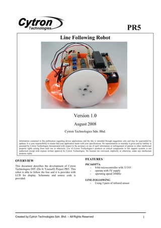
- 1. PR5 Line Following Robot Version 1.0 August 2008 Cytron Technologies Sdn. Bhd. Information contained in this publication regarding device applications and the like is intended through suggestion only and may be superseded by updates. It is your responsibility to ensure that your application meets with your specifications. No representation or warranty is given and no liability is assumed by Cytron Technologies Incorporated with respect to the accuracy or use of such information or infringement of patents or other intellectual property rights arising from such use or otherwise. Use of Cytron Technologies’s products as critical components in life support systems is not authorized except with express written approval by Cytron Technologies. No licenses are conveyed, implicitly or otherwise, under any intellectual property rights. OVERVIEW FEATURES PIC16F877A This document describes the development of Cytron - 8-bit microcontroller with 33 I/O Technologies DIY (Do It Yourself) Project PR5. This - operate with 5V supply robot is able to follow the line and it is provides with - operating speed 20MHz LCD for display. Schematic and source code is provided. LINE-FOLLOWING - Using 3 pairs of infrared sensor Created by Cytron Technologies Sdn. Bhd. – All Rights Reserved 1
- 2. ROBOT . HEAD to TOE PR5 – Line Following Robot SYSTEM OVERVIEW Comparator PIC16F877A MOTOR IR Sensor (line follow) GENERAL DESCRIPTION PR5 is an open source microcontroller Do It Yourself kit. This PIC microcontroller based project designed for user to start develop smart robot which capable of line following. It also provides buzzer for user to indicate the condition or status of the robot that useful for debugging and testing. PIC16F877A This powerful (200 nanosecond instruction execution) yet easy-to-program (only 35 single word instructions) CMOS FLASH-based 8-bit microcontroller packs Microchip's powerful PIC® architecture into an 40- or 44-pin package and is upwards compatible with the Figure 1 PIC16C5X, PIC12CXXX and PIC16C7X devices. Figure 1 shows the pin diagram for PIC16F877A. For Features of the device: more information about the PIC microcontroller, please refer to the datasheet. The datasheet can be found in • 256 bytes of EEPROM data memory microchip web site at: http://www.microchip.com • self programming • 2 Comparators • 8 channels of 10-bit Analog-to-Digital (A/D) converter PIC START-UP KIT SK40A • 2 capture/compare/PWM functions • synchronous serial port can be configured as either 3-wire Serial Peripheral Interface (SPI™) or the 2-wire Inter-Integrated Circuit (I²C™) bus • Universal Asynchronous Receiver Transmitter (UART). All of these features make it ideal for more advanced PIC Start-Up Kit SK40A series is a user friendly kit level A/D applications in automotive, industrial, which enable plug n use feature. appliances and consumer applications. This kit is designed to offer: • Compact, powerful, flexible and robust start up platform! • Suitable for hobbyists and expects. • Save development and soldering time. • No extra components required for the PIC to function. Is ready to rock! Created by Cytron Technologies Sdn. Bhd. – All Rights Reserved 2
- 3. ROBOT . HEAD to TOE PR5 – Line Following Robot • All 33 I/O pins are nicely labeled to avoid PIC Start-up Kit SK40A miss-connection by users. • Ready with bootloader hardware allowing user to load program easily via PC serial port to PIC. • No programmer is needed to re-program the PIC. • No more frustrated work plugging PIC out and back for re-programming. • Perfectly fit to 40 pins PIC16F and PIC18F. SK40A come with: • 5V voltage regulator (1A max) • 20MHz oscillator • Reset button Figure 3 • Bootloader button • Bootloader hardware and bootloader serial cable For the instruction of using this PIC SK40A • And all the necessities to eliminate users programmer, please refer to the particular PIC difficulty in controlling the PIC. programmer user’s manual at: http://www.cytron.com.my/listProductCategory.asp Users are able to utilize the function of PIC by directly ?cid=82#51 plugging in the I/O components in whatever way that is convenient to user. With bootloader firmware on PIC, Donut board you can start developing projects and have fun with this kit. This kit comes WITHOUT PIC microcontroller to provide the freedom for user to choose PIC type. HARDWARE This project will require following hardware: a. 1 x PIC16F877A b. 1 x PIC Start-up kit SK40A c. Related electronic components Please refer to Appendix A for the board layout of PR5. The source code and schematic are provided free Figure 4 therefore Cytron Technologies will not be responsible Components: for any further modification or improvement. 1. PIC Start-up Kit SK40A x 1 Comparator (LM324) 2. PIC16F877A x 1 3. IR Receiver x 3 4. IR Emitter x 3 5. LED x 3 6. Trimmer 10K x 3 7. Resistor 330 ohm x 6 8. Resistor 4.7 kohm x 3 9. Comparator LM324 x 1 10. Motor Driver L293D x 1 11. 14 Pins IC Socket x 1 Figure 2 12. 16 Pins IC Socket x 1 The value from the IR sensor is compared with the 13. PCB Connector 2 Ways x 3 value from the preset which can be adjusted by user. 14. PCB Connector 5 Ways x 2 The output is logic 1 if IR sensor value is larger than 15. Rainbow Cable 5 Ways x 1 preset and vise versa. The LED is used to indicate logic 16. Wrapping Wire x 3 1 or logic 0. The LED will turn ON when logic 1 and 17. RC Servo Motor C36S (modified) x 2 turn OFF when logic 0. 18. Robot Base x 1 Created by Cytron Technologies Sdn. Bhd. – All Rights Reserved 3
- 4. ROBOT . HEAD to TOE PR5 – Line Following Robot 19. Servo Wheel x 2 Just three simple steps 20. Screw for Wheel x 8 21. Castor BTU-720 x 2 22. 9V Battery Snap x 1 Step1 23. 4AA Battery Holder x 1 24. Donut Board x 1 SOFTWARE Flow Chart: Start Initialize PIC Step2 Follow Start Button Yes the line pressed? No Step3 For more information about the software for this system, please refer to the source code provided. The explanation of each instruction is provided in the Line Following Algorithm Concept source code as the comment of each line. Now that we have learn about IR sensor, we will move on to line following. In line following, you will have to The source code is provided free and Cytron know about IR sensor and also controlling motors. For Technologies will not be responsible for any further modification or improvement. this project, we will be applying what we have learnt in PR4. But first of all you will have to learn about controlling motor. Created by Cytron Technologies Sdn. Bhd. – All Rights Reserved 4
- 5. ROBOT . HEAD to TOE PR5 – Line Following Robot 1. Controlling The Motor middle sensor and right sensor. A view of the 1.1 Basic placement of the sensors is as below: When we say motor, we actually mean D.C. motor. This is because we are using D.C power supply for all of our projects. As an example, the PIC16F877A needs 5V DC to power it where else the Bluetooth modules needs 3.3V DC. There are different types of DC motors available in the market such as DC geared motor, servo motor and stepper motor, but for this project, we will be focusing on servo motor. Typical servo motors only allow 180° rotate which is not suitable for a wheeled robot to move from a place to another The distance between 2 sensor depends on the width. place. Thus, we had made some modification to the The sensor should be placed in such a way that servo motor so that it can rotate 360° continuously. maximum distance of two sensors is equal to the width At the remaining of the text, we only concentrate of the line as shown in figure below. on the continuous rotating servo motor. To move the motor, just connect the power supply to the terminal on the motor while to move it in opposite direction, change the polarity of the connection between the power supply and the terminal. For this line following robot, we will be Tuning the comparator to trigger at certain intensity of using two motors. infrared light is called “Teaching”. We will need a small Philips screw driver to tune the VR or preset to 1.2 Motor driver L293D desire voltage. Place the robot on a white floor with black tape (line) as shown in picture: In a line following robot, usually the motor is powered by a different source from the main circuit the motor will move faster and more powerful. For our application, 4.8V is more suitable. From the schematics below, you can see that there is 6 pins connected to the microcontroller and 2 pins to each motor. Out of which is the microcontroller. Therefore, an additional component is required to enable the microcontroller to control the motors. For this project, we will be using L293D for this purpose. A servo motor usually needs 4.8V or 6.0V to operate. Higher voltage will generate more power to the motor, thus the 6 pins, 3 is for the left motor and the other 3 is for the right motor. Now lets concentrate on only 1 side of L293D, 3 pins for the To teach the robot for line detection, you may follow microcontroller and 2 pins for the motor. Form the these steps: 3 pins, 2 pins is for the direction of the motor and 1 pin (connected to Pin C1 or C2) is for PWM 1. Adjust the robot so that the center infrared which is to control the speed of the motor. If sensor is on top of white floor, make sure the controlling of speed is not required, just provide wheels and castor of the robot touches the this pin with 5 volt to enable it to move. The floor properly. direction of the motors depends on the connection 2. Use the screw driver to adjust the preset of of the terminal but can also be determined through center sensor until indicator LED (center) the program. Therefore, the sample program has to light ON. be modified according to your robot. 3. Now adjust the robot to move the center sensor towards the black line where the 2. IR sensors reflection of infrared is poor. For this project, we will be using three pairs of IR 4. At this point, make sure the indicator LED is sensors which will be attached to the bottom of the OFF. If the LED is still on, it means you have robot. These 3 sensors will be classified as left sensor, Created by Cytron Technologies Sdn. Bhd. – All Rights Reserved 5
- 6. ROBOT . HEAD to TOE PR5 – Line Following Robot over tune the preset. Tune it back so that the 1. Get the electronic components on hand indicator is OFF. and solder them up! 5. Repeat step a. - d. for a few time and make sure the indicator LED ON and OFF correctly Prepare your donut board! Solder the SK40A onto at the right spot. your donut board. Follow the schematic that is 6. Repeat step a. - e. to "teach" left sensor and shown in Appendix A. If you are not sure, you can right sensor. test it out first on your protoboard. It is advisable 7. Now your robot has been "taught". to start with the sensor part and test it first before soldering the motor part. This is because the Let’s see how this robot can follow line based of the sensors can be tested without the need to program response from each sensor. In our discussion, we will the microcontroller. Test the sensors by placing it bypass the comparator by assuming that this robot have on a white surface and after that on a black surface, been taught. Once a particular sensor sensed black line, If the LEDs lights when it is placed on the white it will trigger the PIC. surface and turn off when placed on the black surface, then your sensors are connected correctly. Example of how the sensors function when the robot You can then proceed with your motor part. Make follows a black line on a white floor: sure that all the polarity of the components are according to the schematic. Sensor Response Left Middle Right W B W Go Straight B W W Turn Left W W B Turn Right Where, W = White B = Black 2. Building your robot This is the concept of a line following robot. We can see that when the middle sensor detects the line, the The figure below shows the components for the robot will move forward. This is because the line is in movement of the line following robot. These the center of the robot. But when the left sensor or the components are only recommendations. Other right sensor detects the black line, this means that the motors, wheels, bases and castors that you like can robot have strayed from the line. If the robot strayed to also be used. In this chapter, we will be learning the right, the left sensor will detect the line and the how to assemble all the components shown to build brain will react by turning left to go back to the line. the robot. As for the right sensor, it reacts in the opposite way. 3. Coordinating the motor and sensor Now that you know how the sensors detect a line, we will continue to learn how the robot moves. The robot uses the concept of two separate moving wheels. The table below shows the combination of the wheels to move the robot in the desired direction. Left Wheel Right Wheel Movement 1 Forward Forward Forward 2 Backward Backward Backward 3 Forward Stop Right Turn 4 Stop Forward Left Turn Sharp 5 Forward Backward 2.1 Assembling the motors and base Right Turn Sharp Left 6 Backward Forward i. First, screw the two motors on both side of the Turn acrylic base included. Make sure that the shaft of the motors is positioned in the center of the When you reach this part, you have learnt the basic base. concept of line following algorithm. What you have to do now is Prepare your PCB board! Created by Cytron Technologies Sdn. Bhd. – All Rights Reserved 6
- 7. ROBOT . HEAD to TOE PR5 – Line Following Robot ii. After the motor have been mounted on the base, assemble the wheels onto the motor and screw it using the silver small screw that is 3. Programming the microcontroller included with the motor. After all robot have been completed, its time to program the microcontroller. For this project, we will be using C programming. The bootloader will still be used to program it (refer to PR3). There will be some changes when using MPLAB and Bootloader. Download the sample source code (PR5.hex) and try it on your robot. If the wheel does not turn in the required direction, just download the program (PR5.c) and change it to suit your robot. iii. For the castor, insert the bolts through the 3.1 MPLAB and PICC Lite hole on the front and on the back and tighten the nuts. • Install MPLAB • Install PICC Lite 1. Start the MPLAB IDE program. 2. Set up a new project. Select Project-> Project Wizard then Click Next to continue. 2.2 Completing the Assembly 3. Choose the correct device which is PIC16F877A and click Next to continue. Stick the completed circuit (main circuit and sensors) and battery holders onto the base. The arrangement of the circuit and holders are completely dependant on your creativity. 4. Select HI-TECH PICC Toolsuite as your language toolsuite from the Active Toolsuite drop-down menu. Click Next to continue. . Created by Cytron Technologies Sdn. Bhd. – All Rights Reserved 7
- 8. ROBOT . HEAD to TOE PR5 – Line Following Robot 5. Enter a name and select the location for the project. Click Next to continue. 7. Download the sample program to the folder that you have created the project. 8. Right click on the Source files and select Add Files. 6. Click Next then select Finish to complete. 9. Add the PR5.c file. 10. Now you are ready to build your project. Select Project-> Build All or press CRTL+F10. 11. MPLAB will generate a HEX file that will be transferred to the PIC Microcontroller using the bootloader. Created by Cytron Technologies Sdn. Bhd. – All Rights Reserved 8
- 9. ROBOT . HEAD to TOE PR5 – Line Following Robot 3.2 Bootloader 3.3 Changing the program • Please click here to review how to setup bootloader. • There is some changes when using C programming: For source code written in C language with PICC Lite Compiler, there must be offset 200 in the “PICC Linker” option (Please refer to the pictures below). The figure above is part of the program. If the robot is not moving in the direction that is supposed to, change the value for Port B that is circled in the program above. The four values represent RB7, RB6, RB5 and RB4 respectively. So to change the direction of the right wheel, change the value for RB7 and RB6 (first 2 digit) from 01 to 10. For the left wheel, change the value for RB5 and RB4 (next 2 digit) from 01 to 10. If the value is 00, that means that the motor stops. The value for ‘j’ has to be the same as Port B. WARRANTY No warranty will be provided as this is DIY project. Thus, user is advice to check the polarity of each electronic component before soldering it to board. Created by Cytron Technologies Sdn. Bhd. – All Rights Reserved 9
- 10. ROBOT . HEAD to TOE PR5 – Line Following Robot Appendix A: Donut Board Layout CytRon SK40A Comparator LM324 LED Motor drive L293D LED LED Resistor 330Ohm Created by Cytron Technologies Sdn. Bhd. – All Rights Reserved 10
- 11. ROBOT . HEAD to TOE PR5 – Line Following Robot Appendix B: Schematic Prepared by Cytron Technologies Sdn. Bhd. 19, Jalan Kebudayaan 1A, Taman Universiti, 81300 Skudai, Johor, Malaysia. Tel: +607-521 3178 Fax: +607-521 1861 URL: www.cytron.com.my Email: support@cytron.com.my sales@cytron.com.my Created by Cytron Technologies Sdn. Bhd. – All Rights Reserved 11