Download to read offline
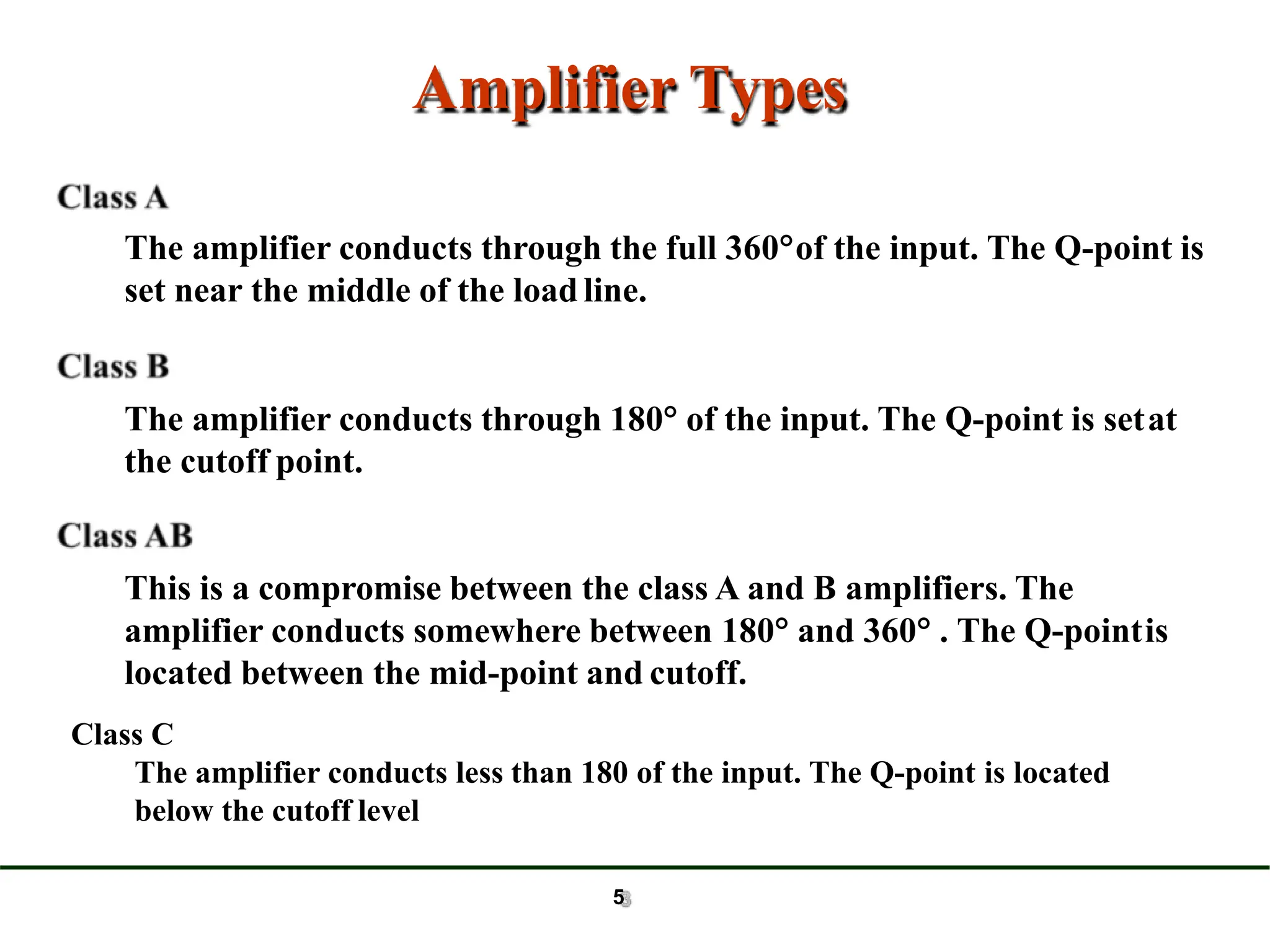
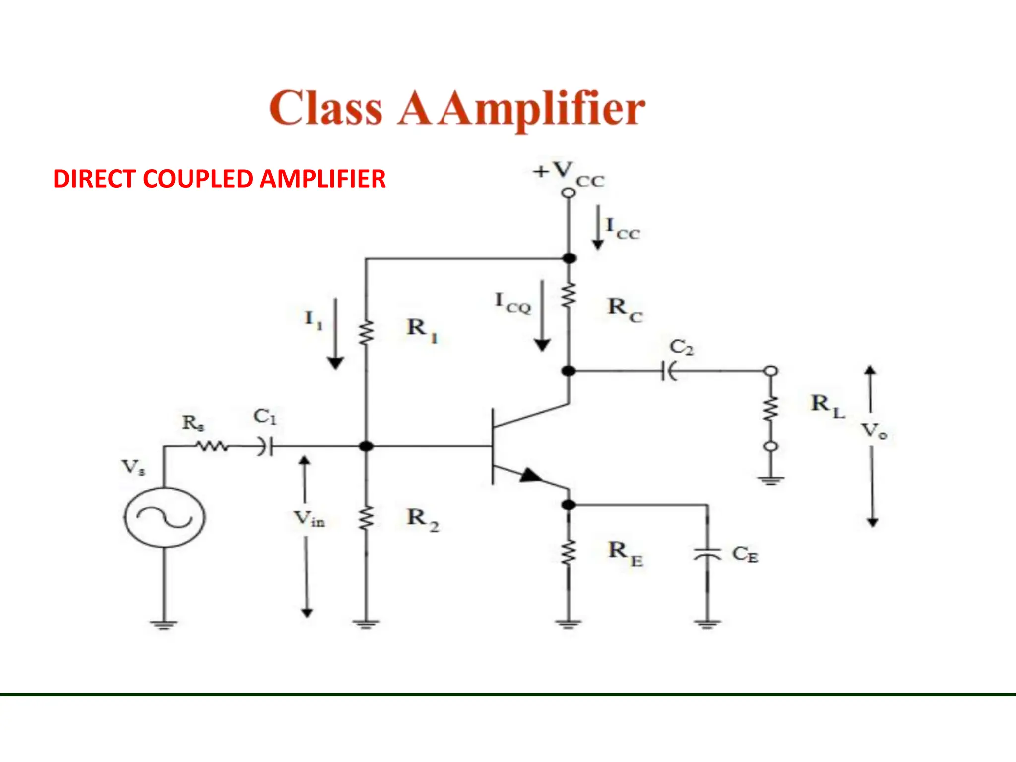
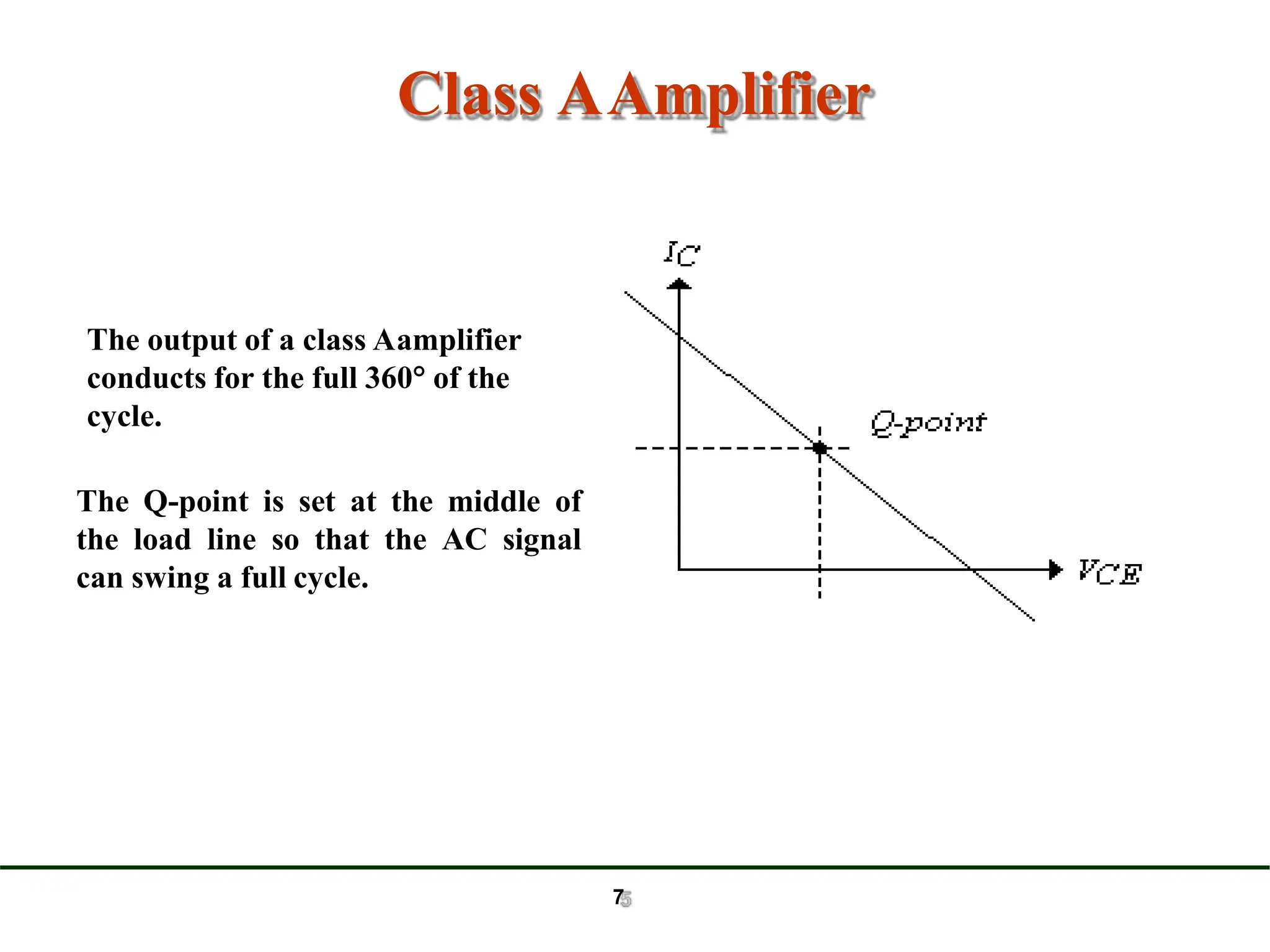
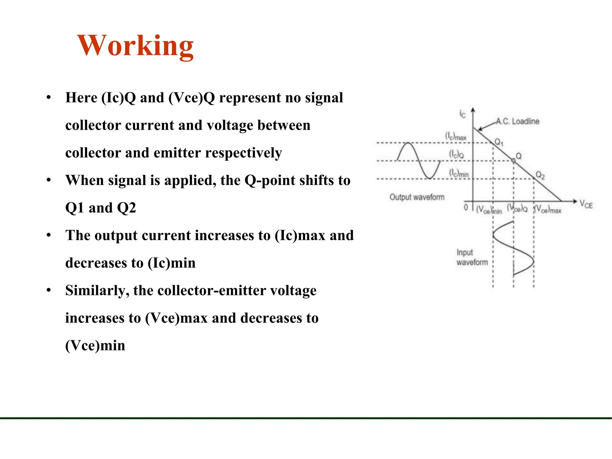
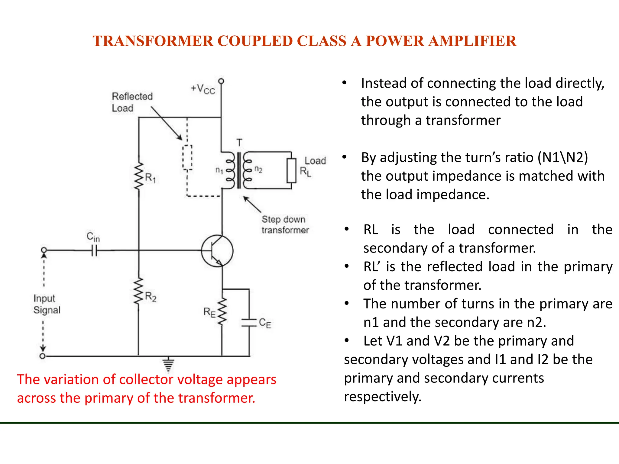
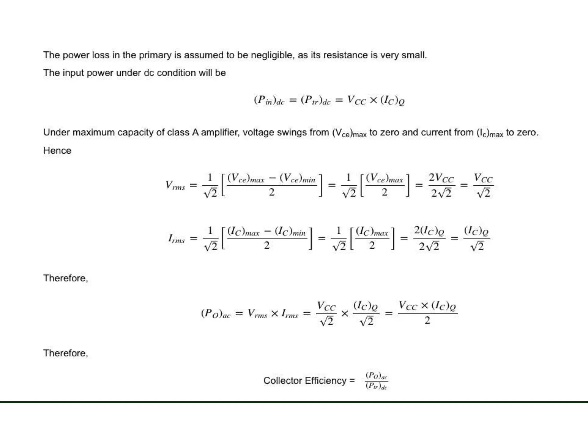
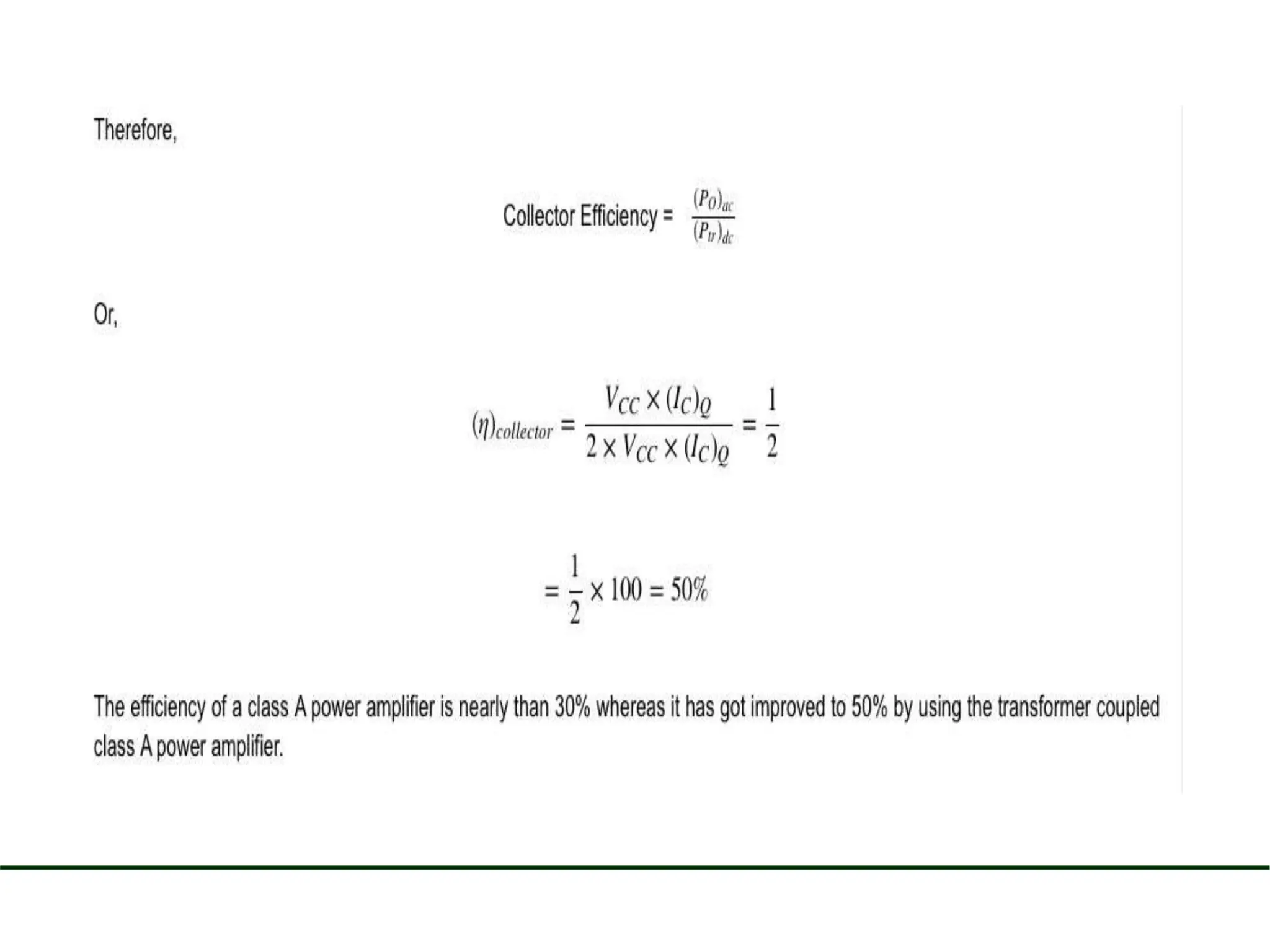
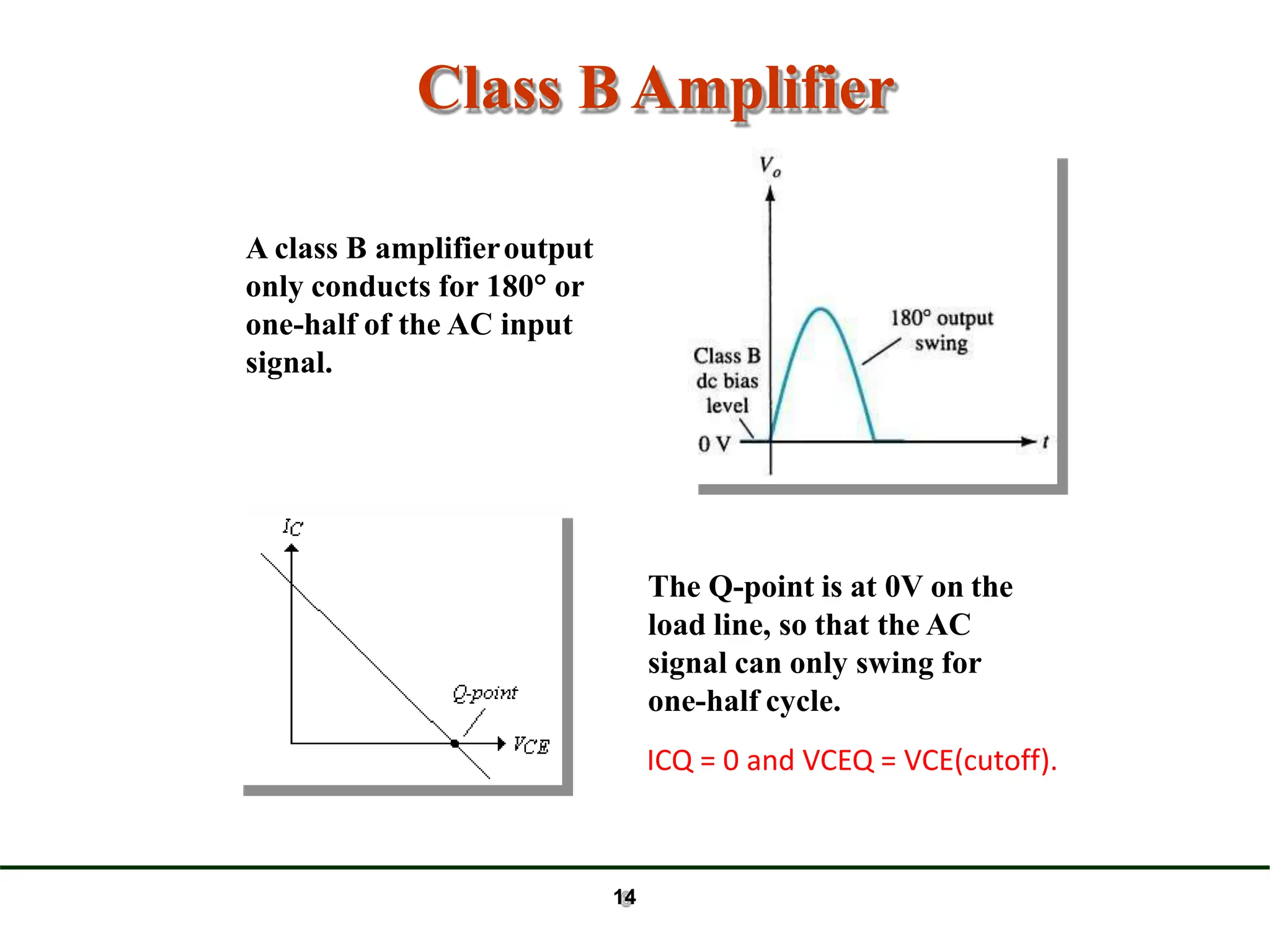
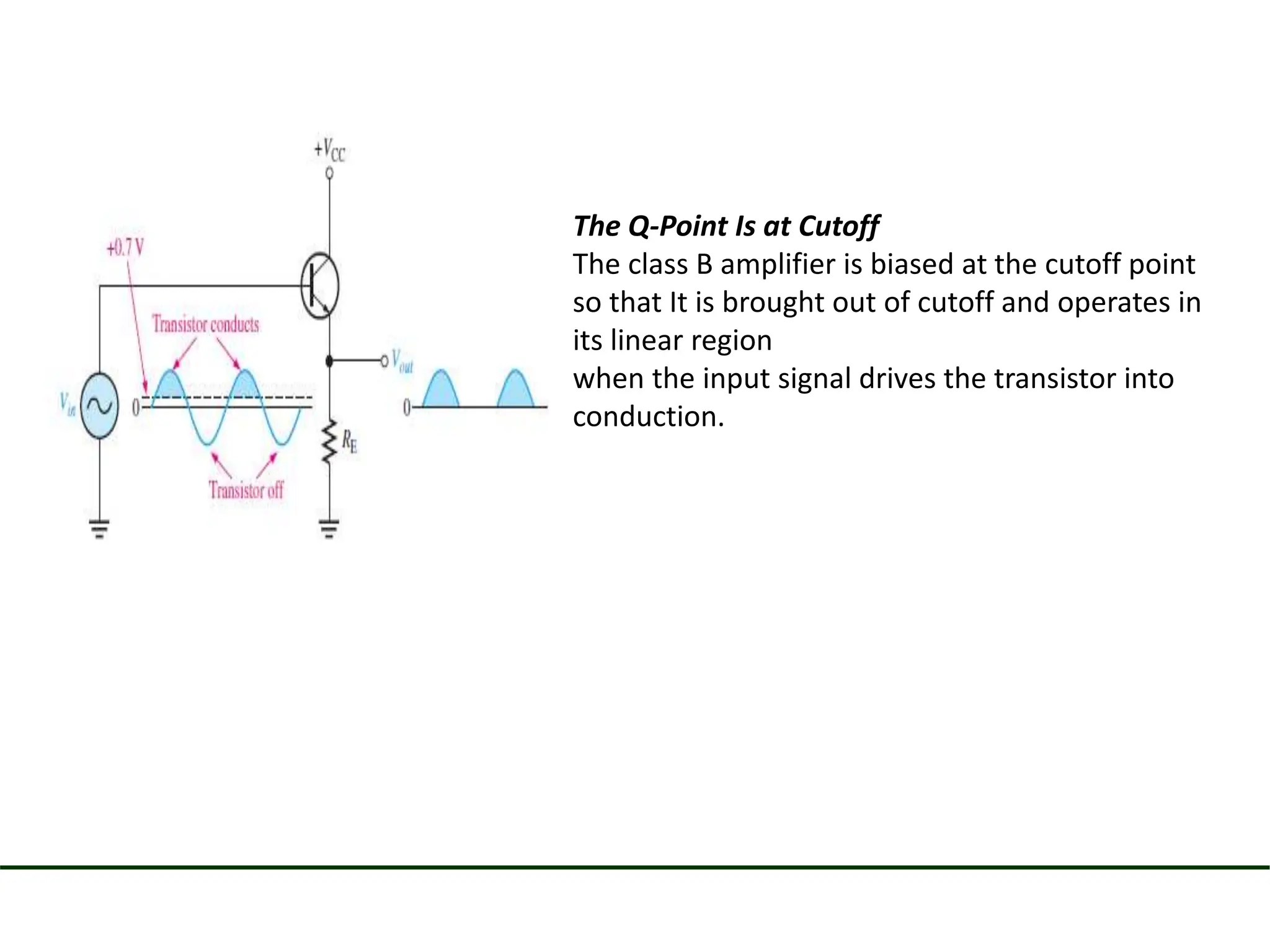
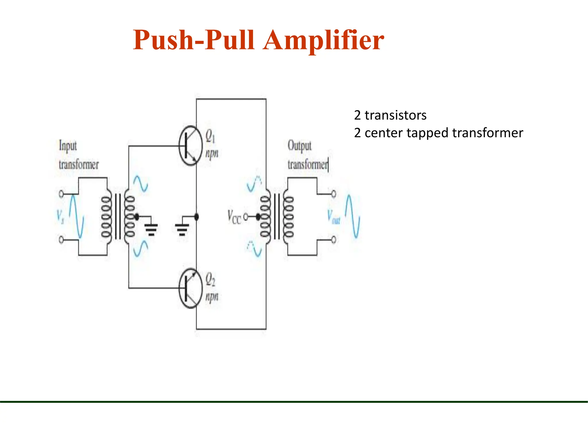
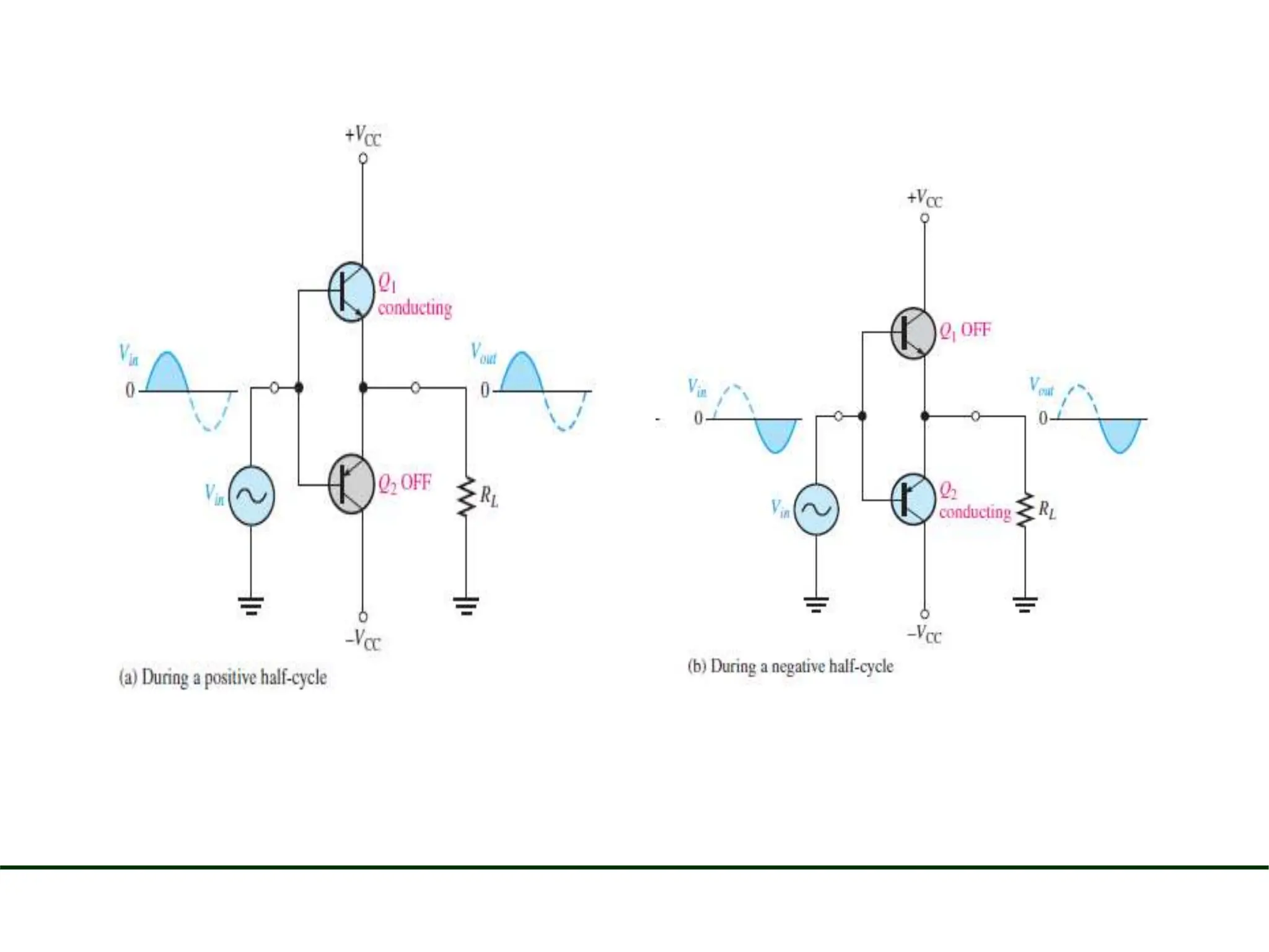
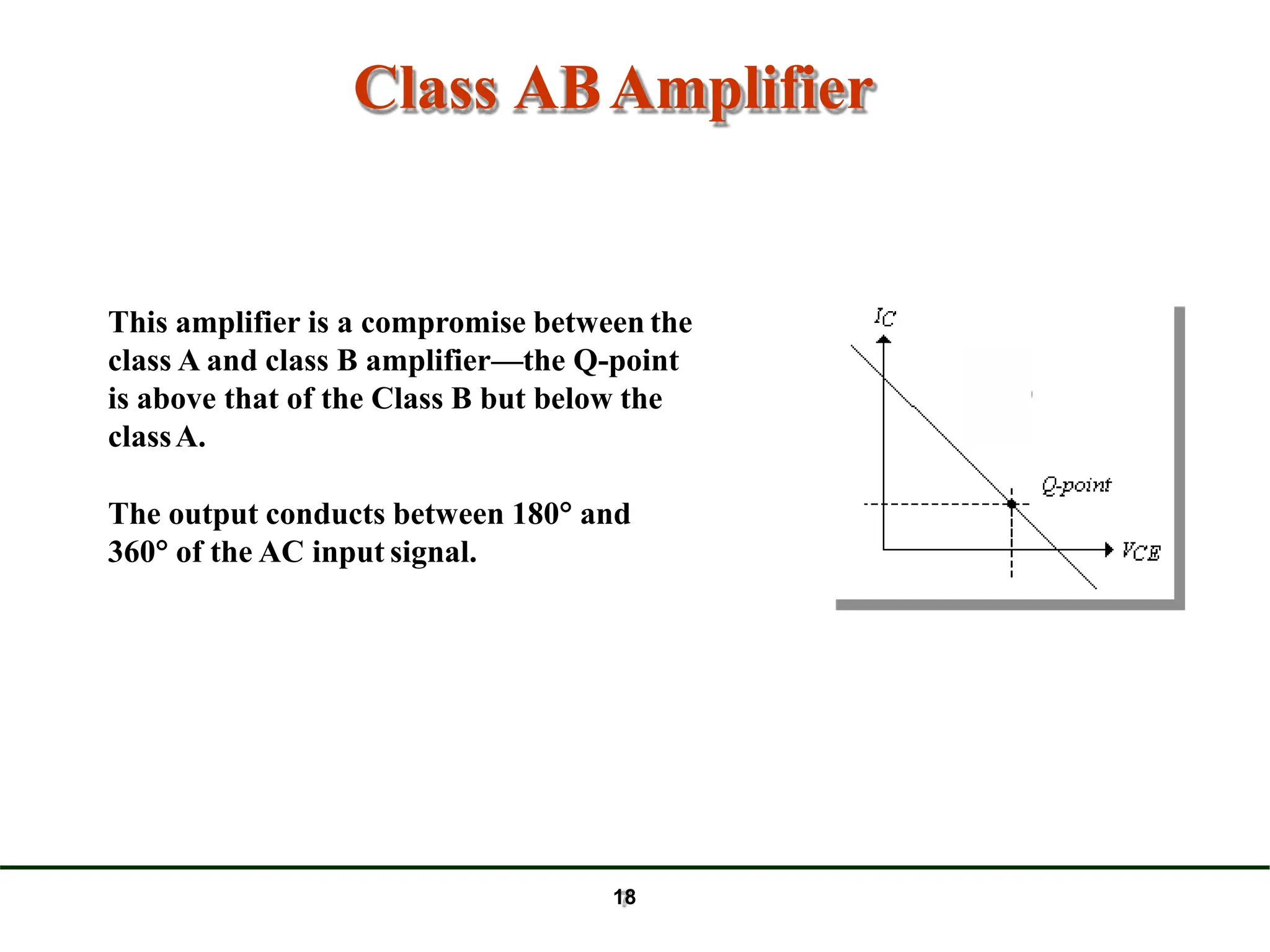
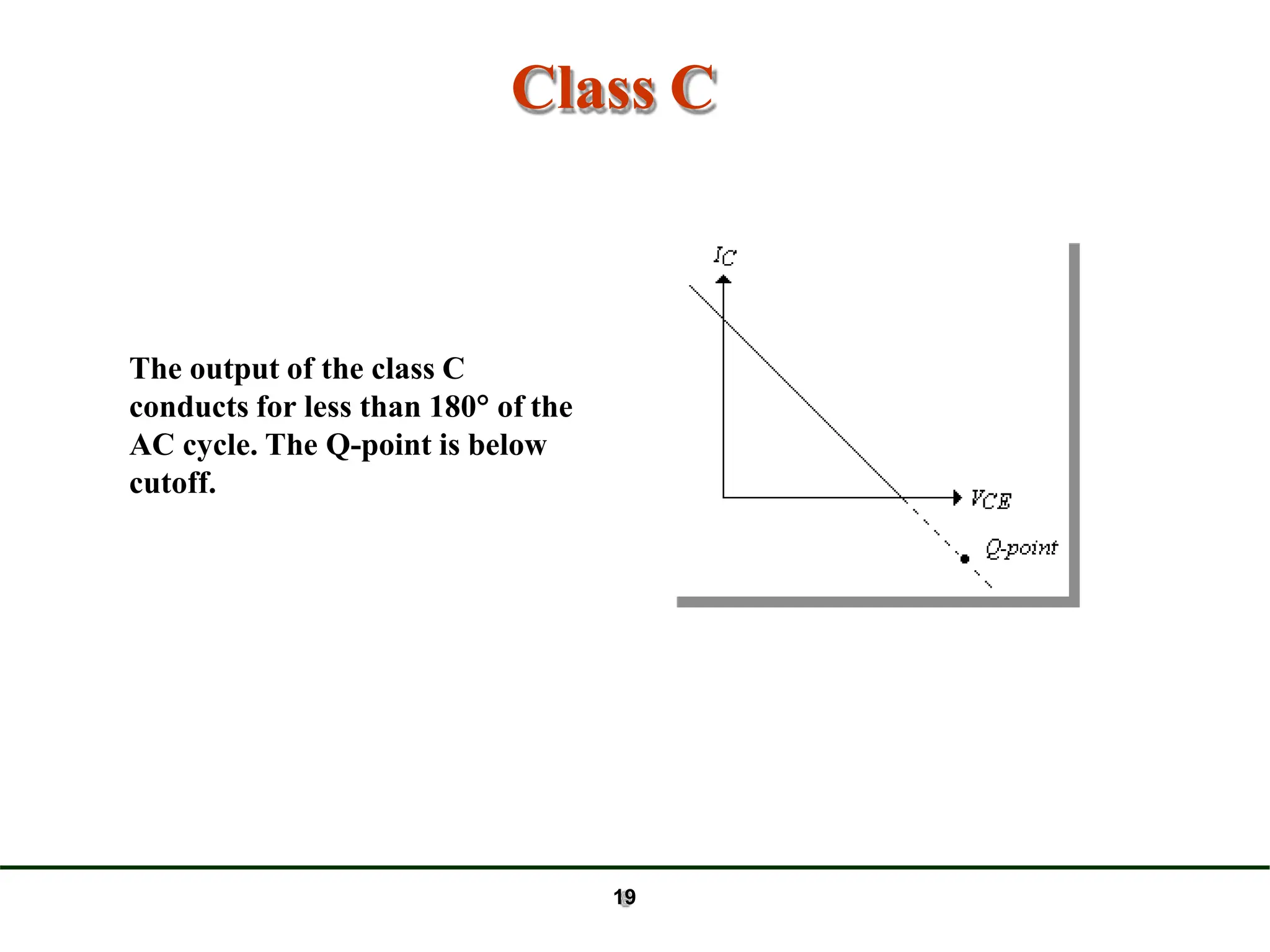
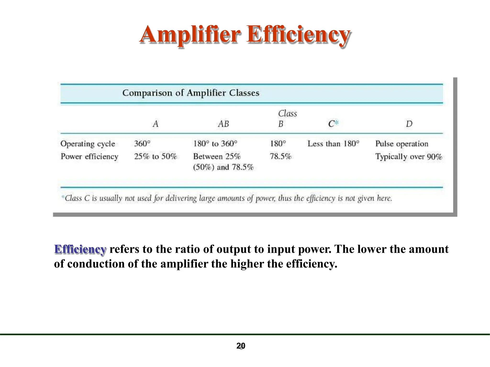
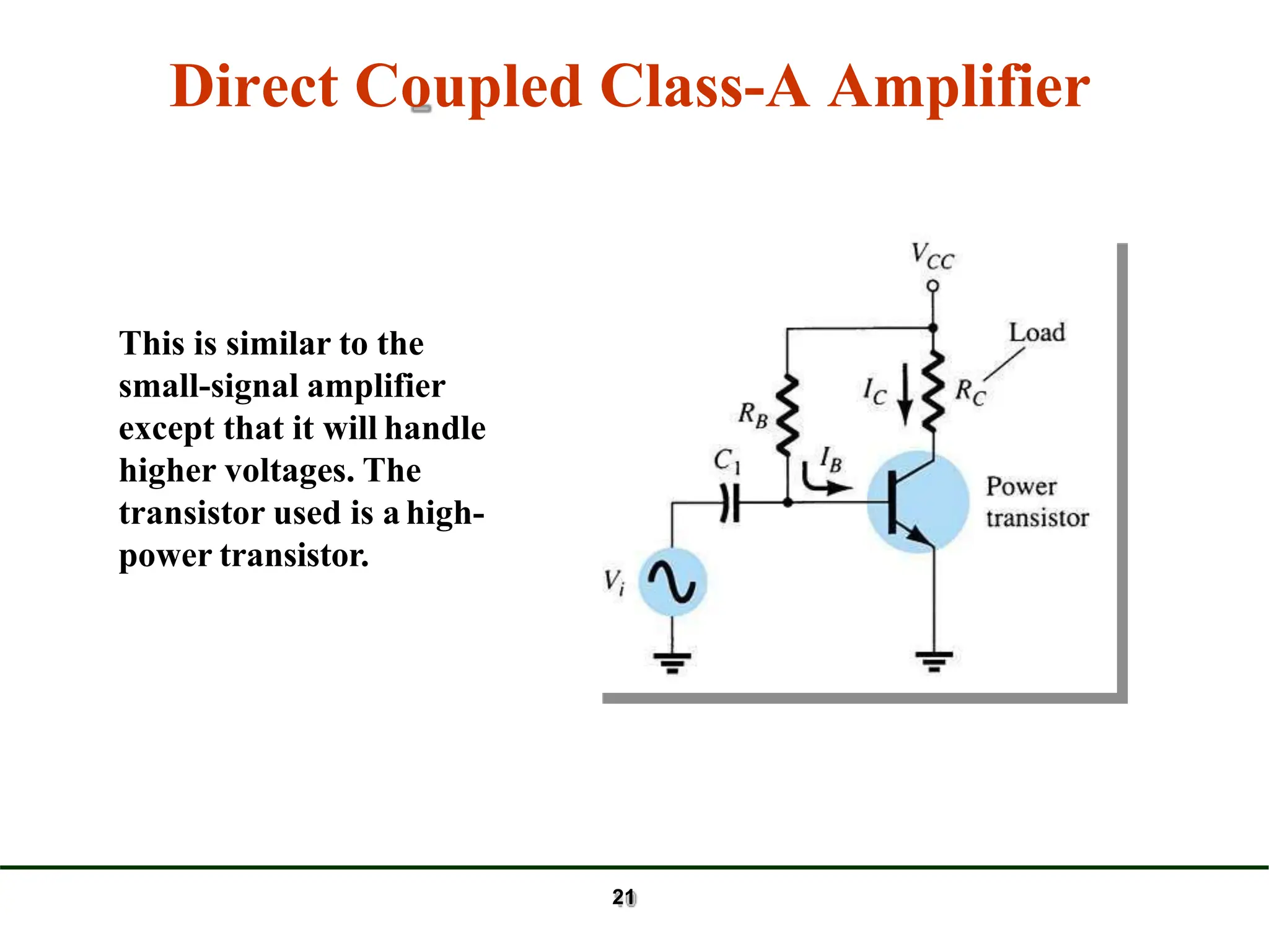
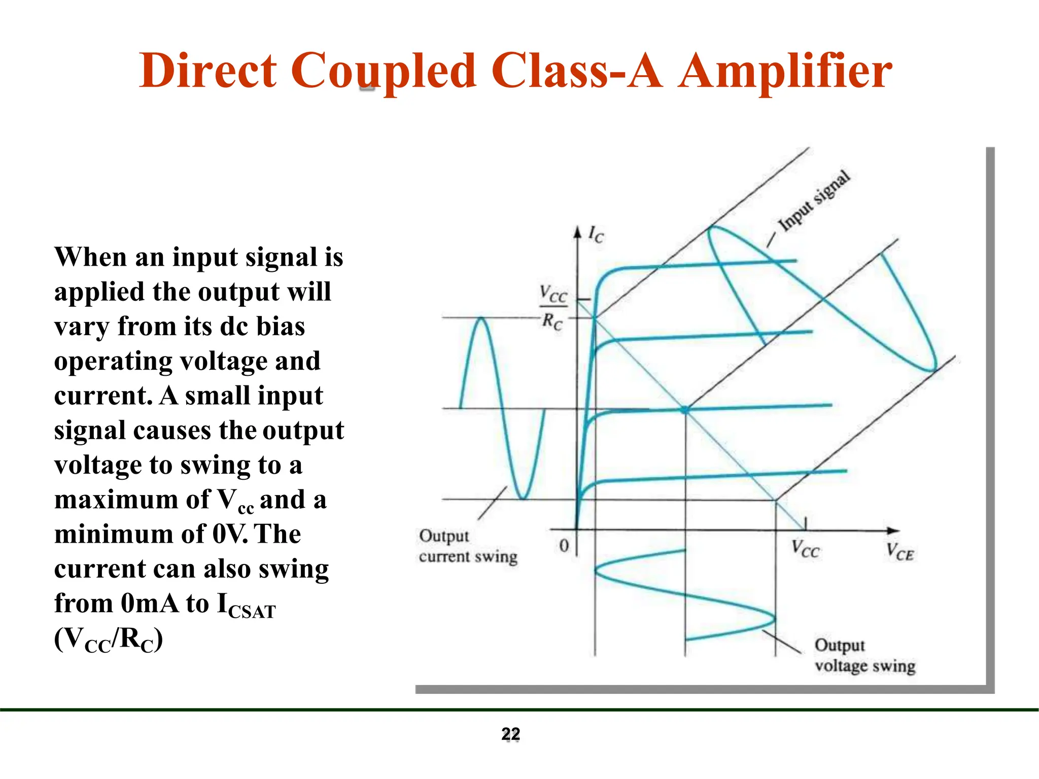
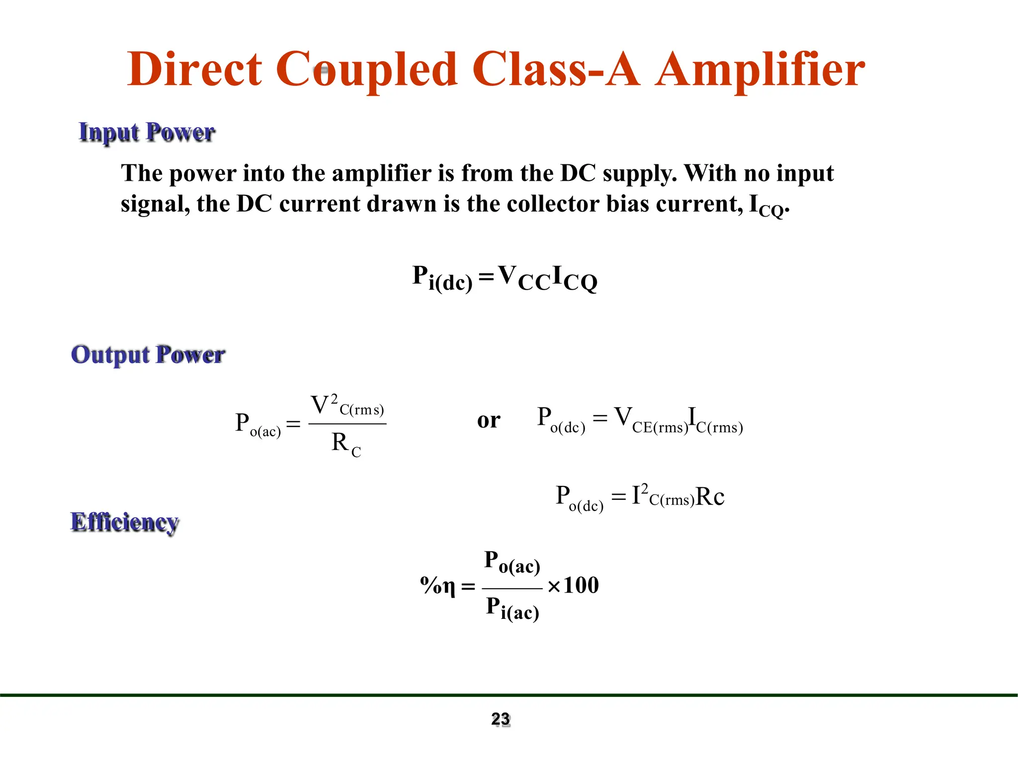
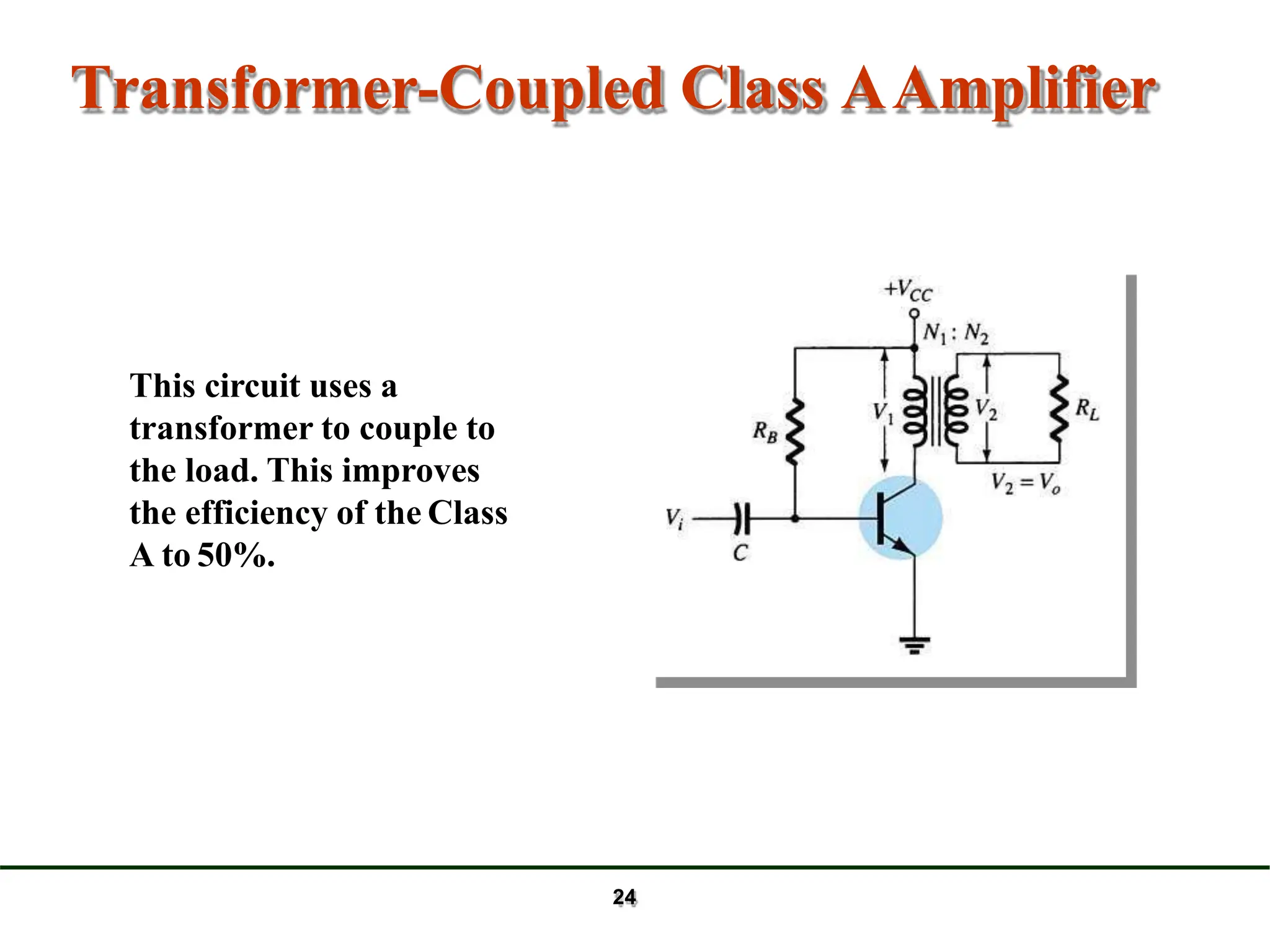
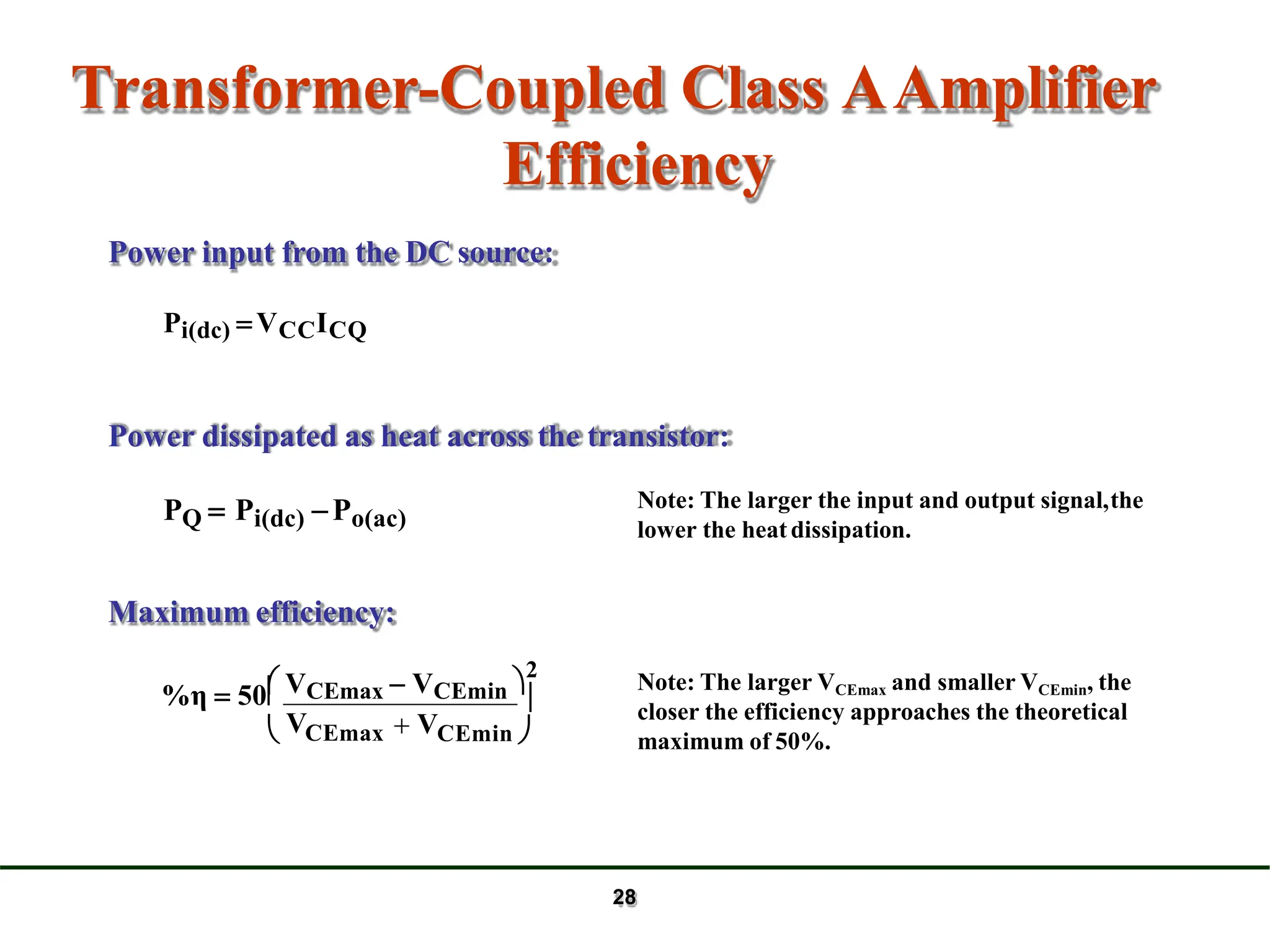
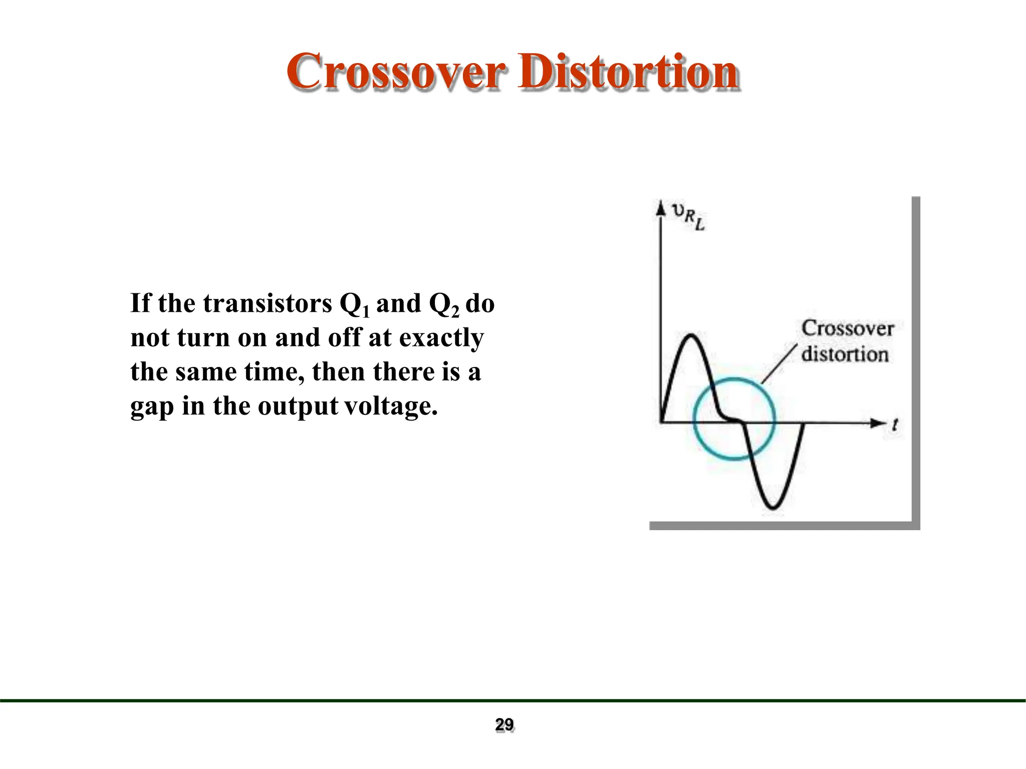
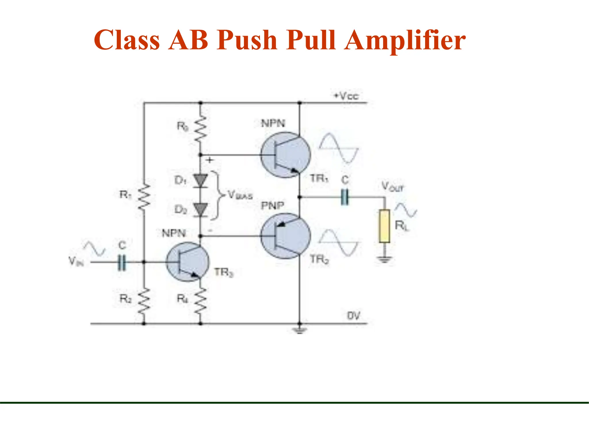
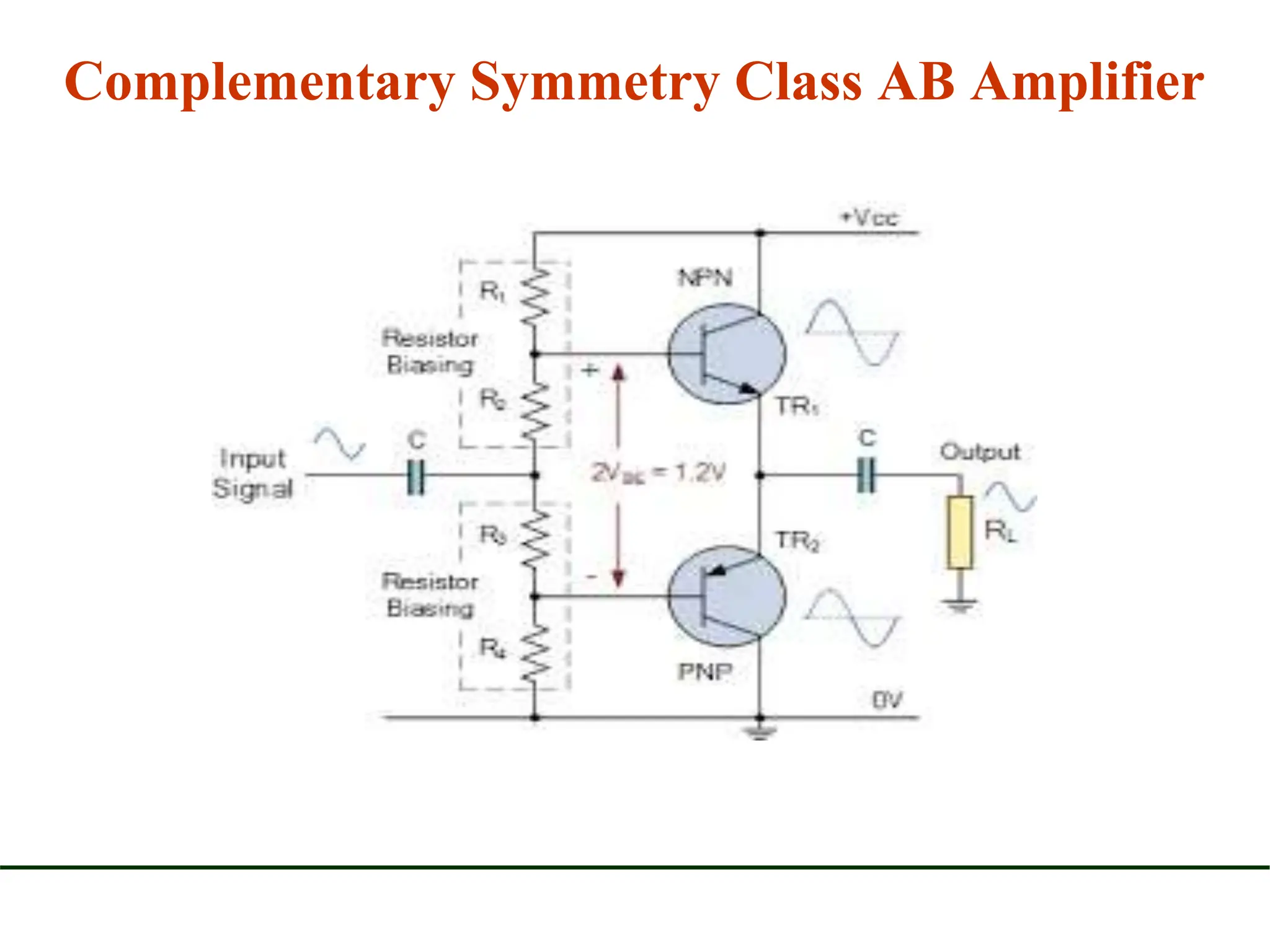

This document discusses different types of power amplifiers: - Class A amplifiers conduct over the full 360 degrees of the input signal cycle and have the Q-point set in the middle of the load line, providing low distortion but low efficiency of around 25%. Transformer coupling can improve efficiency to 50%. - Class B amplifiers conduct over 180 degrees with the Q-point at cutoff, improving efficiency but introducing crossover distortion if not implemented as a push-pull circuit. - Class AB is a compromise between A and B, conducting between 180-360 degrees. Class C amplifiers conduct less than 180 degrees and require an LC tank circuit to generate a full sine wave output.


![July07 4[1].1 power_amplifiers01](https://cdn.slidesharecdn.com/ss_thumbnails/july0741-200727121307-thumbnail.jpg?width=640&height=640&fit=bounds)


![RF Module Design - [Chapter 6] Power Amplifier](https://cdn.slidesharecdn.com/ss_thumbnails/rfch6-150613070347-lva1-app6891-thumbnail.jpg?width=640&height=640&fit=bounds)