Downloaded 1,892 times

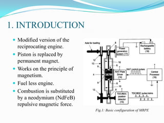
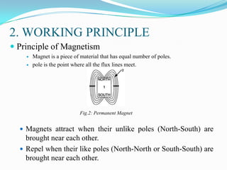
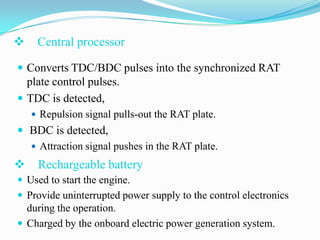
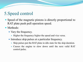
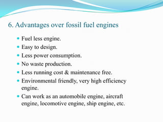
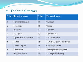


This document presents information on a magnetic repulsion permanent engine (MRPE). It consists of 3 sentences: The MRPE works by using repulsion and attraction forces between permanent magnets and a ferromagnetic plate to push and pull magnetic pistons inside cylinders, replacing the combustion process of a traditional engine. It describes the basic components, including the magnetic pistons, cylinder, flywheel rod, repulsion-attraction plate, and control electronics to synchronize piston movement. The document outlines the working principle, operation cycle, speed control, and advantages over fossil fuel engines, such as being fuel-less, low maintenance, and environmentally friendly.


