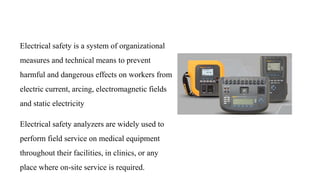
Presentation by Andreas Schleicher Tackling the School Absenteeism Crisis 30 ...
Electrical safty analyzer machine ppt pptx
1. Electrical safety is a system of organizational
measures and technical means to prevent
harmful and dangerous effects on workers from
electric current, arcing, electromagnetic fields
and static electricity
Electrical safety analyzers are widely used to
perform field service on medical equipment
throughout their facilities, in clinics, or any
place where on-site service is required.
2. An electrical safety analyzer is an instrument used to perform various electrical safety tests to check that the device
under test is in compliance with electrical safety requirements. Evaluating a product for electrical safety usually includes
the following tests:
Ground continuity test: ensures that a clear path is available between all exposed metal surfaces and the power system
ground.
Leakage current test: evaluates whether current that flows between an AC source and the ground does not exceed a
specified limit.
Insulation resistance test : calibrates the quality of the electrical insulation used.
High voltage test (dielectric withstand test): measures the ability of an electrical product to withstand a high voltage
applied between a product’s electrical circuit and the ground.
3. The purpose is to verify that all conductive parts of a product that are
exposed to user contact are connected to the power line ground (the
“green” wire).
The theory is that if an insulation failure occurs that connects power
line voltage to an exposed part and a user then comes into contact with
that part, current will flow through the low resistance ground path to
the green wire, tripping a circuit breaker or blowing a fuse, rather than
flowing through the higher resistance of the user’s body. Connecting
all exposed conductive parts solidly to ground safely diverts the
current away from the person.
Ground Continuity Test:
4. Since many older homes may be wired as 2-wire systems without solid
ground connections, regulatory agencies require all products
manufactured with 3-wire cords to pass the same tests as ungrounded
products. In such cases, the user is protected by the electrical
insulation rather than by the safety ground.
Ground continuity tests are normally performed with a low current DC
signal that checks to ensure that the ground connection has a resistance
of less than 1 ohm. Ground continuity testing is not only helpful in
determining how well a product will fare during a laboratory
investigation, but also is useful in a production line environment to
ensure quality and user safety.
Ground Continuity Test:
5. A polarization test is usually performed as part of one of the other tests, such as a line voltage leakage or a hipot test. It
is a simple test that verifies that a product supplied with a polarized line cord (either a 3-prong plug or a 2-prong plug
with the neutral prong larger than the other) is properly connected.
The test may be just a visual inspection or it may be a wiring continuity check. A main purpose of such a test is
to ensure that the line and neutral conductors are not interchanged
Polarization Test
6. Leakage currents:
Most safety testing regimes for medical electrical equipment involve the measurement of certain "leakage currents", because
the level of them can help to verify whether or not a piece of equipment is electrically safe. the various leakage currents that
are commonly measurable with medical equipment safety
1- Causes of leakage currents.
2-
3-
4- Patient leakage current
5- Patient auxiliary current
Earth leakage current.
Enclosure leakage current or touch current
7. Causes of leakage currents
The currents that flow from or between conductors that are insulated from earth and from each other are called leakage
currents, and are normally small. However, since the amount of current required to produce adverse physiological
effects is also small, such currents must be limited by the design of equipment to safe values.
For medical electrical equipment, several different leakage currents are defined according to the paths that the currents
take.
There is no such thing as perfect insulation or infinite impedance. The amount of current that flows depends on:
a. the voltage on the conductor.
b. the capacitive reactance between the conductor and earth.
c. the resistance between the conductor and earth.
8. Earth leakage current
Earth leakage current is the current that normally flows in the
earth conductor of a protectively earthed piece of equipment.
Most of the earth leakage current finds its way to earth via the
impedance of the insulation between the transformer primary
and the inter-winding screen, since this is the point at which the
insulation impedance is at its lowest.
Figure. Earth leakage current path
9. Enclosure leakage current or touch current
Enclosure leakage current is defined as the current that flows
from an exposed conductive part of the enclosure to earth
through a conductor other than the protective earth conductor.
Figure. Enclosure leakage current path
10. Patient leakage current
Patient leakage current is the leakage current that flows through
a patient connected to an applied part or parts. It can either flow
from the applied parts via the patient to earth or from an
external source of high potential via the patient and the applied
parts to earth.
Figure. Patient leakage current path from equipment
Figure. Patient leakage current path to equipment
11. Patient auxiliary current
The patient auxiliary current is defined as the current that
normally flows between parts of the applied part through the
patient, which is not intended to produce a physiological effect
Figure. Patient auxiliary current path
12. Insulation Resistance Test
The effectiveness of electrical insulation is tested through electrical leakage measurements (results in mA or µA) while the
level of isolation is often tested using a dielectric or insulation test. During a dielectric, or hipot test, a high voltage (up to
4000V AC) is applied across different parts of the electronic design in order to stress the dielectrics. Results are displayed in
mA or µA - similar to that of leakage current measurements.
An insulation resistance test applies a lower DC voltage, typically between 250-500V DC, across different parts of the
electronic design. The results are displayed in Mega ohms (MΩ).
Insulation resistance is normally checked by applying 500V DC between:
Input (live conductors, both phase and neutral, connected together) and enclosure (protective ground in class 1).
Insulation Resistance EUT to Ground.
Output (applied parts) and enclosure (Protective ground in class 1).
Insulation Resistance Applied Parts.
Input (phase and neutral) and output (applied parts) for floating type applied parts (BF and CF).
Insulation Resistance Applied Parts to Mains
13. Insulation Resistance EUT to Ground
This test is used to verify that the mains parts are adequately insulated from ground (class I)
or the enclosure (class II).
Figure 12: Insulation test mains parts to protective ground, class I
Figure 13: Insulation test mains parts to non-grounded accessible
conductive parts, class I and II
During this test, 500V D.C. is applied between the ground pin and both the live and
neutral pins of the appliance mains supply plug
14. Insulation Resistance Applied Parts
This test is used to verify that the applied parts are adequately insulated from ground (class I) or the enclosure (class II).
This test is applicable to class I and class II, BF and CF equipment only.
During this test, 500V D.C. is applied between the ground pin (class I) or the enclosure (class II) and all the applied parts
combined.
Figure: Insulation test applied parts to protective ground, class I
Figure 15: Insulation test applied parts to non-grounded accessible conductive
parts, class I and II
15. Insulation Resistance Applied Parts to Mains
This test is used to verify that the applied parts are adequately
insulated from the mains parts and is applicable to class I and class
II, BF and CF equipment only.
Figure: Insulation test mains parts to applied parts, class I and II
During this test, 500V D.C. is applied between all the applied parts
combined and both the live and neutral pins of the appliance mains
supply plug.
16. High Voltage Testing | Low Frequency Constant DC High Frequency Surge or Impulse Test:
Types of High Voltage Test
There are mainly four types of high voltage testing methods applied on high voltage equipment and these are:
• Sustained low frequency tests.
• Constant DC test.
• High frequency test
• Surge or impulse test.
17. This test is generally done at power frequency (50 Hz or 60 Hz). This is most commonly
used high voltage test. This test are carried out on a specimen of insulating material to
determine and ensure, dielectric strength, dielectric losses of the insulating material.
Sustained Low Frequency Test
18. High Voltage DC Test
High voltage DC test is normally applicable to those equipment which are used in
high voltage DC transmission system. But this test is also applicable for high voltage
AC equipment, when high voltage AC testing is not possible due to unavoidable
condition.
19. High Frequency Test
The insulators used at high voltage transmission system, may be subjected
to breakdown or flash-over during high frequency disturbances. The high
frequency disturbances occur in the HV system due to switching operations
or any other external causes. High frequency in power may cause failure of
insulators even at comparatively low voltage due to high dielectric loss and
heating.
20. Surge Test or Impulse Test
There may be great influence of surge or lighting on the transmission lines.
These phenomena can breakdown transmission line insulator and it may also
attack, the electrical power transformer connected at the end of the
transmission lines. Surge test or impulse tests are very high or extra high
voltage tests, carried out for investing the influences of surges or lightning on
the transmission equipment.