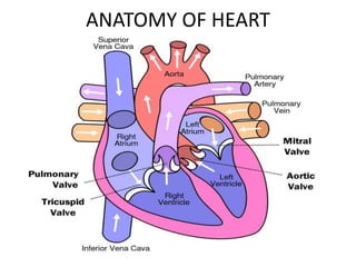
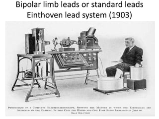
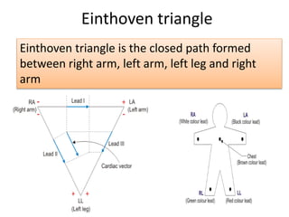
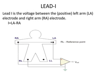
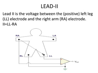
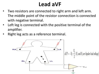
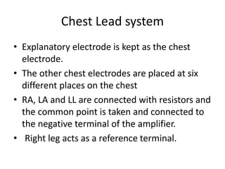
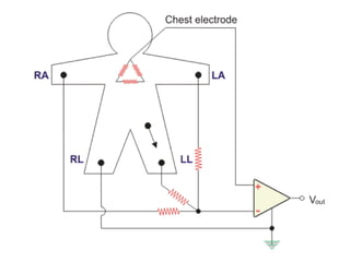
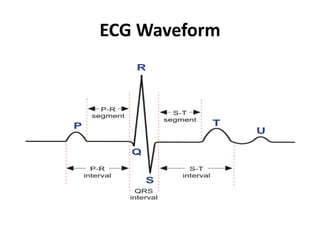
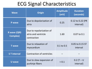
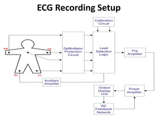
VELTECH
DEPARTMENT OF ECE
Electrocardiography- ECG
Prepared By,
V.Mahalakshmi,
Assistant Professor,
Department of ECE,
Veltech
UNIT – I
ELECTRO-PHYSIOLOGY
AND
BIO-POTENTIAL RECORDING
ECG
 Electrocardiography - Study of the electrical
activity of heart muscles.
 Electrocardiograph - Instrument used to
measure the electrical activity of heart
muscles.
 Electrocardiogram – Recorded wave pattern
of electrical activity of heart muscles.
ANATOMY OF HEART
The heart comprises four chambers:
• Right atria and Right ventricles.
• Left atria and Left ventricles.
The heart comprises four valves:
• tricuspid valve
• mitral valve (bicuspid valve)
• pulmonary valve
• aortic valve
The heart comprises three layers:
• Pericardium
• Endocardium
• Myocardium
The heart comprises three blood vessels:
• Veins, capillaries and arteries
The heart comprises two circulation system:
• Circulatory system
• Systemic Circulation
ECG LEAD SYSTEMS
• Bipolar limb leads or standard leads
Lead- I, Lead- II, Lead- III
• Augmented unipolar limb leads
AvR (Augmented voltage right)
AvL (Augmented voltage left)
AvF (Augmented voltage foot)
• Chest leads (10-12 lead system)
• Frank lead system
Bipolar limb leads or standard leads
Einthoven lead system (1903)
Einthoven triangle
Einthoven triangle is the closed path formed
between right arm, left arm, left leg and right
arm
LEAD-I
Lead I is the voltage between the (positive) left arm (LA)
electrode and right arm (RA) electrode.
I=LA-RA
LEAD-II
Lead II is the voltage between the (positive) left leg
(LL) electrode and the right arm (RA) electrode.
II=LL-RA
LEAD-III
Lead III is the voltage between the (positive) left leg
(LL) electrode and the left arm (LA) electrode.
III=LL-LA
Augmented Unipolar Leads
• In this system, ECG is recorded between single
exploratory electrode and central terminal.
• Central terminal relates to the center of the
body. Two equal and large resistors are used.
• The remaining portion of the limb electrode
forms the exploratory electrode.
• In this lead system, a very small increase in
ECG voltage can be found.
LEAD-III
Lead III is the voltage between the (positive) left leg
(LL) electrode and the left arm (LA) electrode.
III=LL-LA
Lead aVR
• Two resistors are connected to left arm and left leg. The
middle point of the resistor connection is connected
with negative terminal.
• Right arm is connected with the positive terminal of the
amplifier.
• Right leg acts as a reference terminal.
Lead aVL
• Two resistors are connected to right arm and left leg.
The middle point of the resistor connection is connected
with negative terminal.
• Left arm is connected with the positive terminal of the
amplifier.
• Right leg acts as a reference terminal.
Lead aVF
• Two resistors are connected to right arm and left arm.
The middle point of the resistor connection is connected
with negative terminal.
• Left leg is connected with the positive terminal of the
amplifier.
• Right leg acts as a reference terminal.
Chest Lead system
• Explanatory electrode is kept as the chest
electrode.
• The other chest electrodes are placed at six
different places on the chest
• RA, LA and LL are connected with resistors and
the common point is taken and connected to
the negative terminal of the amplifier.
• Right leg acts as a reference terminal.
Chest Lead system
V1 – Fourth intercostal space of right
sternal margin
V2 – Fourth intercostal space at left
sternal margin
V3 – Midpoint between V2 and V4
V4 – Fifth intercostal space at mid –
clavicular line
V5 – Same as V4 position but on
anterior auxiliary line
V6 – Same as V4 position but on mid
auxiliary line
ECG Waveform
ECG Signal Characteristics
Wave Origin
Amplitude
(mV)
Duration
(seconds)
P wave
Due to depolarization of
atria
0.25
0.12 to 0.22 (PR
interval)
R wave (QRS
Complex)
Due to repolarization of
atria and ventricle
contraction
1.60 0.07 to 0.1
T wave
Due to relaxation of
myocardium
0.1 to 0.5
0.05 to 0.15 ST
interval
S T interval Contraction of ventricles – –
U wave
Due to slow expansion of
purkinje fibers
< 0.1
0.2 (T – U
interval)
ECG Recording Setup
Defibrillator Protection Circuit
• The one end of the electrode leads are
connected along RA, LA, chest and LL of the
patient. The other end of electrode passes
through defibrillator protection circuit. The
protection circuit has buffer amplifier and
over-load voltage protection circuit.
Lead Selection Logic
• This block helps to select the type of electrode
lead system. We can choose either bipolar or
augmented electrode system.
Calibration Circuit
• Calibration is a process that helps to eliminate errors in the
system. Here, any changes in the lead selection circuit results in
artifacts in the ECG output. Therefore, the calibration unit helps
the technician to correct the error in ECG output.
Pre Amplifier
• An instrumentation amplifier and a differential amplifier with
high gain and high CMRR is used as pre amplifier.
Power Amplifier
• The output unit is driven with power amplifier. After the signal is
amplified using pre-amplifier it goes to the power amplifier. The
output unit is attached with a pen motor. A high electrical power
is required to initiate recording with pen recorder. Hence, a high
power gain amplifiers are used as power amplifier.
Feedback Network
• Feedback network is used to provide damping to the pen motor.
Output Display Unit
• Either a CRO or a pen chart recorder acts as the output device.
ECG

ECG

  • 1.
    VELTECH DEPARTMENT OF ECE Electrocardiography-ECG Prepared By, V.Mahalakshmi, Assistant Professor, Department of ECE, Veltech
  • 2.
  • 3.
    ECG  Electrocardiography -Study of the electrical activity of heart muscles.  Electrocardiograph - Instrument used to measure the electrical activity of heart muscles.  Electrocardiogram – Recorded wave pattern of electrical activity of heart muscles.
  • 4.
  • 5.
    The heart comprisesfour chambers: • Right atria and Right ventricles. • Left atria and Left ventricles. The heart comprises four valves: • tricuspid valve • mitral valve (bicuspid valve) • pulmonary valve • aortic valve The heart comprises three layers: • Pericardium • Endocardium • Myocardium The heart comprises three blood vessels: • Veins, capillaries and arteries The heart comprises two circulation system: • Circulatory system • Systemic Circulation
  • 6.
    ECG LEAD SYSTEMS •Bipolar limb leads or standard leads Lead- I, Lead- II, Lead- III • Augmented unipolar limb leads AvR (Augmented voltage right) AvL (Augmented voltage left) AvF (Augmented voltage foot) • Chest leads (10-12 lead system) • Frank lead system
  • 7.
    Bipolar limb leadsor standard leads Einthoven lead system (1903)
  • 8.
    Einthoven triangle Einthoven triangleis the closed path formed between right arm, left arm, left leg and right arm
  • 9.
    LEAD-I Lead I isthe voltage between the (positive) left arm (LA) electrode and right arm (RA) electrode. I=LA-RA
  • 10.
    LEAD-II Lead II isthe voltage between the (positive) left leg (LL) electrode and the right arm (RA) electrode. II=LL-RA
  • 11.
    LEAD-III Lead III isthe voltage between the (positive) left leg (LL) electrode and the left arm (LA) electrode. III=LL-LA
  • 13.
    Augmented Unipolar Leads •In this system, ECG is recorded between single exploratory electrode and central terminal. • Central terminal relates to the center of the body. Two equal and large resistors are used. • The remaining portion of the limb electrode forms the exploratory electrode. • In this lead system, a very small increase in ECG voltage can be found.
  • 14.
    LEAD-III Lead III isthe voltage between the (positive) left leg (LL) electrode and the left arm (LA) electrode. III=LL-LA
  • 15.
    Lead aVR • Tworesistors are connected to left arm and left leg. The middle point of the resistor connection is connected with negative terminal. • Right arm is connected with the positive terminal of the amplifier. • Right leg acts as a reference terminal.
  • 16.
    Lead aVL • Tworesistors are connected to right arm and left leg. The middle point of the resistor connection is connected with negative terminal. • Left arm is connected with the positive terminal of the amplifier. • Right leg acts as a reference terminal.
  • 17.
    Lead aVF • Tworesistors are connected to right arm and left arm. The middle point of the resistor connection is connected with negative terminal. • Left leg is connected with the positive terminal of the amplifier. • Right leg acts as a reference terminal.
  • 18.
    Chest Lead system •Explanatory electrode is kept as the chest electrode. • The other chest electrodes are placed at six different places on the chest • RA, LA and LL are connected with resistors and the common point is taken and connected to the negative terminal of the amplifier. • Right leg acts as a reference terminal.
  • 20.
    Chest Lead system V1– Fourth intercostal space of right sternal margin V2 – Fourth intercostal space at left sternal margin V3 – Midpoint between V2 and V4 V4 – Fifth intercostal space at mid – clavicular line V5 – Same as V4 position but on anterior auxiliary line V6 – Same as V4 position but on mid auxiliary line
  • 21.
  • 22.
    ECG Signal Characteristics WaveOrigin Amplitude (mV) Duration (seconds) P wave Due to depolarization of atria 0.25 0.12 to 0.22 (PR interval) R wave (QRS Complex) Due to repolarization of atria and ventricle contraction 1.60 0.07 to 0.1 T wave Due to relaxation of myocardium 0.1 to 0.5 0.05 to 0.15 ST interval S T interval Contraction of ventricles – – U wave Due to slow expansion of purkinje fibers < 0.1 0.2 (T – U interval)
  • 23.
  • 24.
    Defibrillator Protection Circuit •The one end of the electrode leads are connected along RA, LA, chest and LL of the patient. The other end of electrode passes through defibrillator protection circuit. The protection circuit has buffer amplifier and over-load voltage protection circuit. Lead Selection Logic • This block helps to select the type of electrode lead system. We can choose either bipolar or augmented electrode system.
  • 25.
    Calibration Circuit • Calibrationis a process that helps to eliminate errors in the system. Here, any changes in the lead selection circuit results in artifacts in the ECG output. Therefore, the calibration unit helps the technician to correct the error in ECG output. Pre Amplifier • An instrumentation amplifier and a differential amplifier with high gain and high CMRR is used as pre amplifier. Power Amplifier • The output unit is driven with power amplifier. After the signal is amplified using pre-amplifier it goes to the power amplifier. The output unit is attached with a pen motor. A high electrical power is required to initiate recording with pen recorder. Hence, a high power gain amplifiers are used as power amplifier. Feedback Network • Feedback network is used to provide damping to the pen motor. Output Display Unit • Either a CRO or a pen chart recorder acts as the output device.