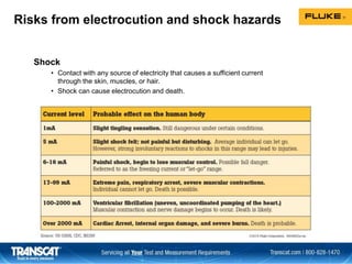
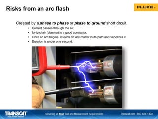
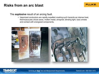
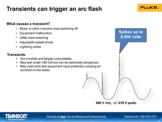
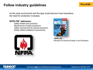
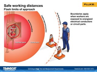
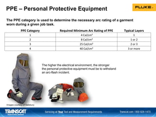
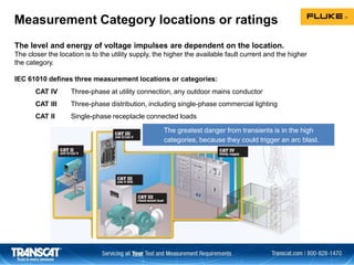
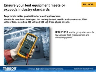
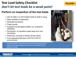
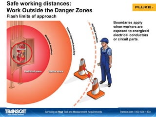
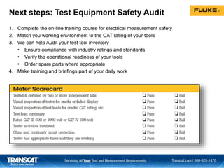
Electrical safety risks include shock, arc flash, and arc blast. Shock can cause electrocution and death from contact with any live electricity source. An arc flash is created by a short circuit and passes current through ionized air, while an arc blast is the explosive result and causes hazards like heat, shock waves, and metal shrapnel. Transients from switching equipment can trigger an arc flash. Proper personal protective equipment and following guidelines like NFPA 70E can reduce risks when working with electricity. Test equipment must be rated for the voltage category of the circuit and independently certified to safety standards to avoid hazards.
Nowadays, it is very important to maintain voltage level. Controlling of that voltage is also important. This Presentation contains methods of voltage control.
High Voltage Safety Operating Procedures for Engineers and TechniciansLiving Online
Safety should be the first consideration for anyone working with electricity, especially high voltage. This workshop introduces participants to all aspects of the procedures required for ensuring safe work in any job involving high voltage.
At the end of this workshop participants will be able to:
Demonstrate approved ways of operating and earthing high voltage equipment to ensure safety of personnel at all times
Identify safe and unsafe working conditions
Identify requirements for a responsible person or appointed operator
Demonstrate a fundamental knowledge of the documentation required for Occupational Safety Acts
Perform live chamber and limited access procedures
WHO SHOULD ATTEND?
Design engineers
Electrical engineers
Electrical technicians
Electrical tradespersons
Electricians
Field technicians
Instrumentation engineers
Plant operators
Project engineers
Staff visiting or working in hazardous areas
MORE INFORMATION: http://www.idc-online.com/content/high-voltage-safety-operating-procedures-engineers-and-technicians-4
It is based on current transformer description
It's working and applications are present in it ,it also includes videos of it's windings and it's inrush ability of transformer, and also about instrument transformer and it's working with applications.Current transformers are used-in measuring high currents and connected with it in parallel to it
Digital Voltmeter, Digital Multi-meter, Digital frequency meterDr Naim R Kidwai
The presentation describes digital voltmeter systems, Ramp type DVM, Dual slope Integrator DVM, Digital Multi-meter: block diagram and charactersitics, Digital Frequency Meter system
This PPT explains about the circuit breaker, and its types. Then about the need and purpose of the circuit breaker. And finally the testing and types of testing of circuit breakers.
Description of Auto-Transformer working principle,Constructional features of Auto transformer,Advantages of Auto transformer,Inductional law in Auto transformer,copper saving advantage in Auto transformer,Types of Auto transformer,Conversion of two-winding transformet to Auto transformer,Disadvantages of Auto transformer,Applications of Auto transformer,Limitations of Auto transformer.
A circuit breaker is an automatically operated electrical switch designed to protect an electrical circuit from damage caused by overload or short circuit. Its basic function is to detect a fault condition and interrupt current flow. Unlike a fuse, which operates once and then must be replaced, a circuit breaker can be reset (either manually or automatically) to resume normal operation. Circuit breakers are made in varying sizes, from small devices that protect an individual household appliance up to large switchgear designed to protect high voltage circuits feeding an entire city.
Thank you very much for checking out my presentation.
If you are a student or a faculty of an engineering college and need to create a presentation, you can contact me. Check out my profile to know how.
This presentation explains about the parallel operation of transformers, along with sym. and unsym. voltage ratios, in brief.
Winding
What is Armature winding?
Terms related to armature winding.
Single layer and double layer windings.
Comparison between closed and open windings.
Types of DC armature winding.
Types of AC armature winding.
Transcat's "Calibration's Role in the Manufacturing Jigsaw Puzzle" PresentationTranscat
Howard Zion, Transcat's Director of Service Application Engineering, discusses how calibration fits into manufacturing or the jigsaw puzzle we call manufacturing. Whether relying on an external commercial calibration supplier or an internal calibration laboratory, there are a number of disconnects that can inadvertently cause problems for the end product and that can be costly!
Learn about practical solutions for automating temperature calibration in the field and at the bench. Transcat and Fluke Calibration cover how to set-up each solution and the pros and cons of each.
Calibration Laboratory Audit Preparation Webinar presented on December 10, 2013 by Keith Bennett, Transcat's Directory of Metrology and Quality Systems
Here are some facts associated with correct battery handling and the related hazards and safety concerns that users of battery encounter while using batteries. This also tells us about some best practices in handling battery.
Medium Voltage Switchgear from RPS Switchgear provides protection of medium voltage power equipment, centralized control and circuits in industrial, commercial, and utility installations http://www.rpsswitchgear.eu
Battery Testing 101 by Megger and TranscatTranscat
In this informative webinar, Andrew Sagl of Megger presents an overview of the various battery testing technologies available as well as how to properly maintain VRLA and VLA batteries.
Turnkey Solutions – the key to successful projects
----------------------------------------------------------------
EPC Solutions has all it takes to design, construct, and operate turnkey electrical substation solutions that efficiently support the reliable supply of electrical power on all voltage levels: decades of practical experience as a contractor and equipment manufacturer and a vast number of successfully completed projects all over the world, unparalleled expertise in all transmission processes, and proven excellence in project management. A distinguished tradition of innovation in power engineering, customized financing solutions, and outstanding quality standards in all production facilities worldwide round out the picture.
EPCS turnkey solutions for high-voltage substations incorporate the strong performance of one of the world’s leading engineering companies and one-stop supplier of power transmission products, solutions, and services. The scope of services comprises consulting, project management, system planning, engineering, commissioning, and comprehensive after-sales support. Centers of competence and branches all over the world create local value and ensure that EPCS experts are within close reach of every project.Customers worldwide benefit from numerous advantages of high-voltage substations from EPCS:
>One-stop approach comprising all technical, financial, and ecological aspects of the station’s entire life cycle
>Customized solutions based on proven EPCS technologies, even for the most challenging demands
>Freedom from coordination efforts and minimized financial and technical risk
Electrical Measurement Safety and Best Practices Webinar Presented by FlukeTranscat
Live one-hour, solutions-based webinar that will benefit anyone who works with live electrical equipment, whether you’re installing, testing, maintaining, monitoring, or troubleshooting. We will cover dangers, safe work practices (including PPE, test tool standards, and ratings), best practices, and good tips for keeping safety top of mind.
High current is a hazard to the turbine and technicians alike. For the turbine, lightning strikes can damage blades and short out electric equipment when not sufficiently grounded. There are ways to handle the high current in lightning. Inside the nacelle, technicians have to diagnose issues to get troubled turbines back into production as soon as possible. Several new smart electrical meters can assist that work.
Tools and Techniques for Commissioning and Maintaining PV SystemsTranscat
This course will review the tests to perform, the science behind why they are necessary, and the appropriate tools to conduct them, including digital multimeters, clamp meters, thermal imaging, insulation resistance, I-V curve tracers, irradiance meters, power quality, and solar asset management software.
Overhead & Underground Electric Safety Webinar Presented by AmprobeTranscat
Join presenter Marco Rossi from Amprobe to learn more about overhead and underground electric safety. This webinar will offer a comprehensive look at the current safety guidelines, discuss best practices, and teach you the basics of underground tracing techniques and equipment functionality.
Data Teknis Gossen Metrawatt Insulation Tester METRISO PROPT. Siwali Swantika
Pemesanan produk, hubungi PT Siwali Swantika melalui WhatsApp, Jakarta : 0811-1519-949 (chat only) | Surabaya : 0811-1519-948 (chat only). Kunjungi website kami di www.siwali.com, untuk detail informasi spesifikasi dan model alat.
Electrical test equipment for high and low voltage systems. Phasing rods, ammeter for overhead powerlines on
systems up to 36kV. Hubungi PT. Siwali Swantika, Jakarta Office : 021-45850618 atau Surabaya Office : 031-8421264
Predictive Maintenance Best Practices Presented by Fluke.pptxTranscat
Join us for this webinar about predictive maintenance best practices. Implementing proactive testing will help reduce downtime and minimize lost revenue. We will be discussing the best maintenance practices, the most important trends, the leading technologies to start a predictive maintenance program with and how much predictive maintenance can save you.
Managing Instrument Calibration and Maintenance Presented by Fluke.pptxTranscat
Join us for this solutions-based webinar on managing instrument calibration and maintenance. In this session, we will demonstrate this process workflow of using DPCs and CMS as a paperless instrument calibration solution. Critical process instruments in process plants often require calibration in place where they are installed in the plants. This requires special purpose portable calibration tools to take to the field to perform the task. These special purpose tools are often referred to as Documenting Process Calibrators or DPCs. DPCs also interface with Calibration Management Software (CMS) to help manage both calibration procedures and calibration results. Included in the session will be a PPT introduction and overview and a live demonstration.
Fluke Product Manager of Process Calibration Tools, Jim Shields and Fluke Process Tools Technical Support Engineer, Bob Crepps are co-presenting on this engaging topic:
Jim Shields is the Product Manager for the Process Calibration group for the Fluke Corporation. Jim has been active in the ISA and education and has actively supported and developed instrumentation curriculum. Jim has delivered instrumentation instructor training for the last 15 years to the USA Electrical trades for the USA International Brotherhood of Electrical Worked at the National Training Institute annual training event. Jim has worked in the field of calibration and metrology, field and bench for over 45 years.
Bob Crepps provides engineering level technical support and product training, worldwide. Bob has over 30 years’ experience providing technical support and training for Barcoding systems, Fiber Channel applications, and for the last 10 years - Process Calibration tools.
For more product information, please visit www.transcat.com
Use of a Druck Pressure Calibrator as a Trouble Shooting Tool Presented by DruckTranscat
This one-hour live, solutions-based webinar is to learn about best practices for using a pressure calibrator as a troubleshooting tool. This webinar is being presented by Stephen Sajben, Pressure Product Specialist from Druck. This is a must-see webinar for instrument technicians to find an ideal solution for your test and calibration applications.
Solar Market Opportunities & Solutions - Presented by FlukeTranscat
Solutions-based webinar geared towards electric vehicle charging station and PV system installers and O&M providers. Learn about common pain points and how to solve them using Fluke’s clean energy tools.
Pinpoint the leading causes of downtime with LinkIQ Cable and Network TesterTranscat
The network is down and you’ll likely have to take it apart, only to find out that the source of the problem is a cabling issue. Since 40% of downtime is caused by issues such as bad connectors, broken cables, and excessive cable length, this new tester is a simple way to quickly identify the source of network downtime and quickly get your systems up and running.
How to Maintain Your Temperature Calibration Equipment WebinarTranscat
In this informative webinar with Fluke Calibration you will learn tips for keeping your calibration baths and temperature calibrators operating at their peak.
You’ve invested a lot of money in your temperature calibration lab. Preventative maintenance is critical to keeping your calibration baths and temperature calibrators running at their best. A few minutes spent now in maintaining your equipment can also save you costly repairs and downtime later.
Identifying Energy Waste in your Plant/Facility Webinar with FlukeTranscat
This informative webinar with Fluke that will highlight the right test tools to use and how they will help you identify areas of energy waste in your plant or facility.
Principals of Low Resistance Testing Webinar with MeggerTranscat
During this webinar you will learn the following:
• What is considered a Low Resistance Test?
• When to measure Low Resistance
• Why measure Low Resistance?
• Benefits of Low Resistance Testing
• DLRO2 - Features and Key Characteristics
Leak Detection & Predictive/Preventative Maintenance Solutions Presented by FLIRTranscat
During this webinar you will learn the following:
• An introduction to leak detection
• Best practices for predictive and preventative maintenance
• Gas leak detection solutions
• Air leak detection solutions
• Partial discharge detection solutions
Elevated Body Temperature Measurement with IR Thermometers and TI Cameras Web...Transcat
During this webinar you will learn the following:
• An introduction to Non-Contact EBT screening and technologies that exist for it
• Summary of guidance from the FDA on Non-Contact EBT screening
• Best practices for Non-Contact EBT screening
• What to look out for when purchasing Non-Contact EBT screening solutions
• What Fluke is doing to support Non-Contact EBT Measurements
Field Pressure Calibration Tips Webinar with Fluke CalibrationTranscat
Please join Transcat and John Lopez from Fluke Calibration. We will discuss the best practices for field pressure calibration as well as the following:
---Pneumatic standards vs Hydraulic standards
---Device cleanliness and contamination
---Stability concerns
Temperature Screening Solutions and Returning to Work Safely Webinar with Ame...Transcat
Please join Chris Leonard - Global Lead - VIRALERT, from AMETEK Land.
In this webinar, Chris will answer key questions about temperature screening and what can be done to safely reopen businesses during the pandemic.
From fundamental principles of non-contact, infrared temperature measurements through to specific, individual cases, we will share over 70 years of expertise in designing instrumentation to measure temperature accurately with you.
Using a Portable Bath to Improve Calibration of Sanitary RTD's and Transmitte...Transcat
Travis Porter from Fluke Calibration will describe how Portable Calibration Baths can improve the calibration throughput and accuracy of sanitary temperature sensors and transmitters.
Elevated Skin Temperature Screening Solutions – How to Get Back to Work Safel...Transcat
Join presenter Russell Hall from FLIR to learn about elevated skin temperature screening. This webinar will discuss the following:
-A History of EST (Elevated Skin Temperature) Solutions
-How to get the best measurements
-Best correlation to core body temperature
-Variance with core body temperatures
-FLIR's EST screening mode
-FLIR's EST screening solutions
Elevated Skin Temperature Screening - How to Get Back to Work Safely with FLIRTranscat
-A History of EST (Elevated Skin Temperature) Solutions
-How to get the best measurements
-Best correlation to core body temperature
-Variance with core body temperatures
-FLIR's EST screening mode
-FLIR's EST screening solutions
Tips for Calibrating Analog Pressure Gauges Webinar Presented by Fluke Calibr...Transcat
This webinar will focus on the theory and application of calibrating analog pressure gauges. Topics include gauge grades, exercising, and considerations for test.
Blind Spots of Low Voltage Testing Webinar Presented by Megger BakerTranscat
Find faults where they begin, not where they end.
When the highest reliability is demanded of your motors, high voltage testing is not just an option - it's a necessity. This webinar will focus on the theory and application of electric motor insulation testing techniques.
Introduction to Temperature Measurement and Calibration Presented by Fluke Ca...Transcat
Temperature is one of the most commonly measured physical parameters. This webinar will cover the best devices to use in temperature measurement and when to calibrate.
How to Calibrate an IR Thermometer Webinar Presented by Fluke CalibrationTranscat
How do you know that your infrared calibrations are accurate?
Topics discussed will include:
-Sources of uncertainty
-Calibration equipment required
-Overview of the calibration procedure
-Review of a sample uncertainty budget
-Recommendations for reporting results
Solutions for your Thermography Program Presented by FLIRTranscat
This webinar will address issues with your thermography camera and program:
-New or inexperienced users that need help knowing what to look at
-Need to improve the time it takes to scan your facility and create that thermography report
-Hard to use or outdated thermal camera
-Need better resolution to quickly and easily identify a problem
-Work outdoors where its hard to view traditional LCD only thermal cameras
-Software that’s easy to use
Hierarchical Digital Twin of a Naval Power SystemKerry Sado
A hierarchical digital twin of a Naval DC power system has been developed and experimentally verified. Similar to other state-of-the-art digital twins, this technology creates a digital replica of the physical system executed in real-time or faster, which can modify hardware controls. However, its advantage stems from distributing computational efforts by utilizing a hierarchical structure composed of lower-level digital twin blocks and a higher-level system digital twin. Each digital twin block is associated with a physical subsystem of the hardware and communicates with a singular system digital twin, which creates a system-level response. By extracting information from each level of the hierarchy, power system controls of the hardware were reconfigured autonomously. This hierarchical digital twin development offers several advantages over other digital twins, particularly in the field of naval power systems. The hierarchical structure allows for greater computational efficiency and scalability while the ability to autonomously reconfigure hardware controls offers increased flexibility and responsiveness. The hierarchical decomposition and models utilized were well aligned with the physical twin, as indicated by the maximum deviations between the developed digital twin hierarchy and the hardware.
Final project report on grocery store management system..pdfKamal Acharya
In today’s fast-changing business environment, it’s extremely important to be able to respond to client needs in the most effective and timely manner. If your customers wish to see your business online and have instant access to your products or services.
Online Grocery Store is an e-commerce website, which retails various grocery products. This project allows viewing various products available enables registered users to purchase desired products instantly using Paytm, UPI payment processor (Instant Pay) and also can place order by using Cash on Delivery (Pay Later) option. This project provides an easy access to Administrators and Managers to view orders placed using Pay Later and Instant Pay options.
In order to develop an e-commerce website, a number of Technologies must be studied and understood. These include multi-tiered architecture, server and client-side scripting techniques, implementation technologies, programming language (such as PHP, HTML, CSS, JavaScript) and MySQL relational databases. This is a project with the objective to develop a basic website where a consumer is provided with a shopping cart website and also to know about the technologies used to develop such a website.
This document will discuss each of the underlying technologies to create and implement an e- commerce website.
About
Indigenized remote control interface card suitable for MAFI system CCR equipment. Compatible for IDM8000 CCR. Backplane mounted serial and TCP/Ethernet communication module for CCR remote access. IDM 8000 CCR remote control on serial and TCP protocol.
• Remote control: Parallel or serial interface.
• Compatible with MAFI CCR system.
• Compatible with IDM8000 CCR.
• Compatible with Backplane mount serial communication.
• Compatible with commercial and Defence aviation CCR system.
• Remote control system for accessing CCR and allied system over serial or TCP.
• Indigenized local Support/presence in India.
• Easy in configuration using DIP switches.
Technical Specifications
Indigenized remote control interface card suitable for MAFI system CCR equipment. Compatible for IDM8000 CCR. Backplane mounted serial and TCP/Ethernet communication module for CCR remote access. IDM 8000 CCR remote control on serial and TCP protocol.
Key Features
Indigenized remote control interface card suitable for MAFI system CCR equipment. Compatible for IDM8000 CCR. Backplane mounted serial and TCP/Ethernet communication module for CCR remote access. IDM 8000 CCR remote control on serial and TCP protocol.
• Remote control: Parallel or serial interface
• Compatible with MAFI CCR system
• Copatiable with IDM8000 CCR
• Compatible with Backplane mount serial communication.
• Compatible with commercial and Defence aviation CCR system.
• Remote control system for accessing CCR and allied system over serial or TCP.
• Indigenized local Support/presence in India.
Application
• Remote control: Parallel or serial interface.
• Compatible with MAFI CCR system.
• Compatible with IDM8000 CCR.
• Compatible with Backplane mount serial communication.
• Compatible with commercial and Defence aviation CCR system.
• Remote control system for accessing CCR and allied system over serial or TCP.
• Indigenized local Support/presence in India.
• Easy in configuration using DIP switches.
Saudi Arabia stands as a titan in the global energy landscape, renowned for its abundant oil and gas resources. It's the largest exporter of petroleum and holds some of the world's most significant reserves. Let's delve into the top 10 oil and gas projects shaping Saudi Arabia's energy future in 2024.
Welcome to WIPAC Monthly the magazine brought to you by the LinkedIn Group Water Industry Process Automation & Control.
In this month's edition, along with this month's industry news to celebrate the 13 years since the group was created we have articles including
A case study of the used of Advanced Process Control at the Wastewater Treatment works at Lleida in Spain
A look back on an article on smart wastewater networks in order to see how the industry has measured up in the interim around the adoption of Digital Transformation in the Water Industry.
Explore the innovative world of trenchless pipe repair with our comprehensive guide, "The Benefits and Techniques of Trenchless Pipe Repair." This document delves into the modern methods of repairing underground pipes without the need for extensive excavation, highlighting the numerous advantages and the latest techniques used in the industry.
Learn about the cost savings, reduced environmental impact, and minimal disruption associated with trenchless technology. Discover detailed explanations of popular techniques such as pipe bursting, cured-in-place pipe (CIPP) lining, and directional drilling. Understand how these methods can be applied to various types of infrastructure, from residential plumbing to large-scale municipal systems.
Ideal for homeowners, contractors, engineers, and anyone interested in modern plumbing solutions, this guide provides valuable insights into why trenchless pipe repair is becoming the preferred choice for pipe rehabilitation. Stay informed about the latest advancements and best practices in the field.
2. Risks from electrocution and shock hazards
Shock
• Contact with any source of electricity that causes a sufficient current
through the skin, muscles, or hair.
• Shock can cause electrocution and death.
3. Risks from an arc flash
Created by a phase to phase or phase to ground short circuit.
• Current passes through the air.
• Ionized air (plasma) is a good conductor.
• Once an arc begins, it feeds off any matter in its path and vaporizes it.
• Duration is under one second.
4. Risks from an arc blast
The explosive result of an arcing fault.
• Vaporized conductors are rapidly expelled creating such hazards as intense heat,
thermoacoustic shock wave, molten metal, shrapnel, blinding light, toxic smoke
and contact with energized components.
5. Transients can trigger an arc flash
What causes a transient?
• Motor or other inductive load switching off
• Equipment malfunction
• Utility load switching
• Adjustable speed drives
• Lightning strike
480 V rms, +/- 678 V peaks
Spikes up to
8,000 volts
Transients:
• Are invisible and largely unavoidable.
• May last under 100 mS but can be extremely dangerous.
• May overcome test equipment input protection causing an
arc/short in the tester.
6. What likely causes these incidents?
1. Racking a circuit breaker
– Inserting or removing a breaker on a
live bus.
2. Lose panel wiring
– A lose conductor that shorts across
another conductor or ground.
3. Removing panel covers
– Retaining screws and fasteners fall
into an unsecured panel against a
live bus.
4. Hand tool shorted across two phases
– Experienced electrician cuts into live
cable with cable shears, shear handle
touches another phase.
5. Using incorrect test probes
– The user gets distracted or hand
slips while measuring phase to
phase or phase to ground while
using old style ¾ inch probe tips.
6. Misuse of measurement tools
– Measuring across phases with
an inline amp meter creating a
short circuit.
– Measuring continuity on a live
circuit with a tool that cannot
withstand full voltage.
– Accidental shorting of phases with
a test lead tip that is too long for
the safety category.
7. 1NFPA-70E –
Standard for Electrical Safety in the Workplace
As the work environment and the type of job become more hazardous,
the need for protection increases.
Follow industry guidelines
NFPA-70E1 addresses:
Safety-related work practices
Maintenance of safety equipment
Safety requirements for special equipment
Safety related installation requirements
8. Boundaries apply
when workers are
exposed to energized
electrical conductors
or circuit parts.
Safe working distances
Flash limits of approach
9. PPE Category Required Minimum Arc Rating of PPE Typical Layers
1 4 Cal/cm² 1
2 8 Cal/cm² 1 or 2
3 25 Cal/cm² 2 or 3
4 40 Cal/cm² 3 or more
The higher the electrical environment, the stronger
the personal protective equipment must be to withstand
an arc-flash incident.
Images courtesy of Salisbury
PPE – Personal Protective Equipment
The PPE category is used to determine the necessary arc rating of a garment
worn during a given job task.
10. NFPA: Test instruments are part of PPE
(Article 110.4):
• Shall be rated for circuits and equipment to which they will be connected*
• Shall be designed for the environment to which they will be exposed, and the
manner in which they will be used.*
• Shall be visually inspected before use. Defective or damaged equipment must
be repaired and tested before being used again*
• The insulation of protective tools, including voltage test indicators, shall be verified
by test and inspection (Article 110.4(5))
* NFPA 70E 110.4(A), 2015 Edition
Reduce the risk by using the right test equipment
IEC 61010: International Standards for low voltage
“test, measurement and control equipment”
11. Measurement Category locations or ratings
CAT IV Three-phase at utility connection, any outdoor mains conductor
CAT III Three-phase distribution, including single-phase commercial lighting
CAT II Single-phase receptacle connected loads
The level and energy of voltage impulses are dependent on the location.
The closer the location is to the utility supply, the higher the available fault current and the higher
the category.
IEC 61010 defines three measurement locations or categories:
The greatest danger from transients is in the high
categories, because they could trigger an arc blast.
12. Ensure your test equipment meets or
exceeds industry standards
To provide better protection for electrical workers
standards have been developed for test equipment used in environments of 1000
volts or less, including 480 volt and 600 volt three-phase circuits.
1International Electrotechnical Commission
IEC 61010 are the group standards for
low voltage “test, measurement and
control equipment”
13. First the category, then the voltage
First know the category you are working in, then choose the appropriate
voltage rating
• The working voltage could be 1,000 V, 600 V or 300 V
• Equipment can be dual rated, meeting both requirements
• If you measure power circuits, you should use a CAT III-600 V or CAT IV-600 V/CAT III-1000 V
meter, in addition to CAT IV-600 V/CAT III-1000 V test leads and probes
Voltage rating by itself can be misleading
• CAT III-1000 V (withstands 8 kV transient) is safer than CAT III-600 V (withstands 6 kV transient)
Bottom line and most importantly,
know the measurement category and voltage you are working in.
14. The test equipment should be
independently tested, marked
and certified.
CAT III-600 V
CAT III-1000 V
CAT IV-600 V
CAT III-1000 V
CAT IV-600 V
Look for CAT markings between input jacks
15. What if I can’t find a rating?
Older Fluke 70 Series-III
CAT II-600 V
Original
Fluke 70 Series
UNDER RATEDNOT RATED
Meters and testers designed and produced prior to 1997
no longer meet code and therefore should be replaced.
16. Independent testing and certification
• IEC sets standards, but does not test or inspect for compliance.
• A manufacturer can claim to “design to” a standard with no independent verification.
• To be UL listed, or CSA or TÜV certified, a manufacturer must employ the
listing agency to test the product’s compliance with the standard.
• Look for the listing agency’s emblem on the meter.
“Listed” vs. “designed to”
Tester must be independently tested,
marked and certified.
18. 1. Verify the voltage detector function is working properly.
2. Make sure the detector is rated for the level of voltage being measured and
is sensitive enough for your application.
3. Make sure that you also wear the appropriate PPE based on the
environment you're in.
4. Make sure the hazardous voltage is not shielded.
Use only a digital multimeter or contact type voltage
tester to test for the absence of voltage.
Non-contact voltage detectors
Non-contact voltage
detectors are a quick,
inexpensive way to check
for the presence of live
voltage on ac circuits,
switches and outlets
before working on them.
19. Live-dead-live testing
Verify the operation of the contact voltage tester
Before beginning the absence of voltage test, check the
test instrument to ensure it is working properly in
accordance with NFPA 70E Article 110.9 (A)(4)
1. Wearing proper PPE, measure a voltage similar to the voltage of the
equipment about to be tested. This would include whether it is ac or dc
and approximately the same magnitude.
2. Now test the circuit that is supposed to be de-energized.
3. Once testing is complete, re-verify the meter is still functioning properly
by going to the same known voltage source and making another
measurement.
20. Operational readiness test
Verify proper operation of test tools on a known voltage source before and after
absence or presence of voltage testing is performed.
Several options:
1. Use a convenient electrical outlet (if available)
2. Access live conductors (posing unnecessary risk)
–Suit up in appropriate PPE arc flash gear
3. No power exists
• The Fluke PRV240 Proving Unit provides a regulated
and fixed ac or dc output voltage of 240 volts specifically
to allow for verification testing of Multimeters,
Clampmeters or testers
When test instruments are used for testing the absence of voltage on conductors or circuit parts
operating at 50 volts or more, the operation of the test instrument shall be verified on a known
voltage source before and after an absence of voltage test is performed.
NFPA70 E 2015 edition Article 110.4 (A)(5) Operation Verification proposed wording change
21. Double insulation, finger guards, shrouds and recessed input
jacks protect against electric shock from accidental contact
with live circuits.
Perform an inspection of the test leads
CAT III-1000 V or CAT IV-600 V/CAT III-1000 V rating
Wear indicator on lead wires
Shrouded connectors
Finger guards
Insulation not damaged (melted, cut, cracked or
stretched)
Connectors: no insulation pulled away from end
connectors
Probe tips: not loose or broken off (too short)
4mm exposed probe tips in CAT III or CAT IV
environments
Test Lead Safety Checklist
Don’t let test leads be a weak point!
22. The amount of exposed metal at the tip of the test lead must match
the energy potential of a given measurement
Minimize exposed metal for safety
In accordance with IEC 61010-031
Safety requirements for hand-held probe assemblies for electrical measurement and test.
Some leads offer extendable tip shrouds
to meet the reduced tip length requirement
Other leads come with tip guards
to minimize exposed metal
The higher the CAT rating the less exposed
metal is allowed at the tip of the test lead.
CAT II – 19 mm (0.75 inch)
CAT IV – 4 mm (0.16 inch)
23. The bottom line ― Safety First
Best practices include:
1. Whenever possible, work on de-energized circuits.
• Follow proper lock-out/tag-out procedures
2. Use well maintained tools and appropriate personal
protective equipment
according to NFPA 70E.
• Safety glasses, insulated tools, insulating gloves, arc-
rated clothing,
arc shields, flash suits, insulating mats, etc.
3. Don’t work alone.
4. Practice safe measurement techniques.
• Always connect the grounded lead first, hot second
• Disconnect the hot lead first, grounded lead second
5. Use the live-dead-live test method.
• Test known circuit, measure target circuit, then re-test
known circuit
24. Built-in protection devices guard against the
most common safety hazards:
Overload protection on
all functions
1000 V high
energy fuses
CAT IV-600 V
CAT III-1000 V
Protection that’s designed in
An industrial grade Fluke meter devotes 10 to 15%
of its components exclusively to protection
1. High voltage transients and danger of arc-over
2. Voltage contact while in continuity or resistance
mode
3. Voltage measurement while test leads are plugged
into the amps jacks
25. Common errors with measurement tools
Connecting a meter to a voltage source with the meter configured
for inline amp measurements.
The amps mode on a meter is almost a short circuit
Measuring ohms or continuity on
a live circuit.
Most older meters cannot handle the full
voltage on the ohms function
26. Handheld Test Tool Safety
Last known earthly
residence of automotive fuse
used to replace original fuse
Test leads
survived intact
How not
to save
time...
27. The wrong
meter to use
on a power
circuit.
Probe tips
burned off
Poor quality
leads and
probes led to
injury.
250V fuse
didn’t open in
time
Handheld Test Tool Safety
29. Fluke incorporates specially designed “high-energy” fuses in our digital multimeters
Designed to keep the energy generated by an electrical short
within the fuse enclosure
• Limit the amount of time current is applied and oxygen
available for combustion
• In addition to the specially designed fuse element,
the high energy fuse is filled with sand
Protection devices provide additional safety
30
High temperatures (up to 10,000F) generated by the energy will melt
the sand and turn it into glass, smothering the fireball by cutting off
the available oxygen
30. Common DMM safety hazards
• Measuring voltage while test
leads are in the current
jacks: short-circuit!
Protection: Fluke meters use
high energy fuses.
• Contact with ac or dc power
source while in Ohms mode.
• Using meter above rated voltage, i.e., on medium voltage
circuits.
• No Protection above rated voltages
Protection: Fluke meters have “Overload Protection”.
Functions are self-protected to the meter’s rated voltage.
Three common errors that are avoidable
31. PRESENTER SLIDE: HIDE
Meter Examples/Demonstrations
• Hold up Fluke 87 with leads in Amps Jack
• To measure amps in-line, you wire your meter in series with the circuit. In order not to interfere
with the measurement , you want your meter to look like a piece of wire. Another word for a
piece of wire is a short circuit. So when you have your leads in the amps input terminals, you
have a dead short across these probe tips. That is why it is so important that your meter has
fused input jacks. And not just any fuse, but a specially designed high energy fuse.
“ If this happens with a properly fused meter, the fuse will blow, and you will not even know it.
to check the fuse, you open the meter, pull out the fuse, close the meter or get another meter, and
measure the ohms or continuity to see of the fuse is open. There is a much easier way to do this,
without even having to open up your meter
The black input jack is common for all measurements. So, by measuring across the Common and
Amps input jacks in Ohms, you can check your fuses without opening the case
(show how to do this while talking)
Never change a fuse with the wrong fuse. It is very important to replace the fuse with the
manufacturer’s suggested high energy fuse Now most of the time you will be using a current clamp
to measure current safely
(play amps input-fuse animation)?
32. Safety Inspection
• In a power circuit, use current clamp accessory.
• In low energy ckt, 10A or less, open the circuit:
– Measure in series (current is the same in a series circuit). The
amps circuit resistance must be small, to have a minimal effect
on the current. This low impedance input requires fuse
protection.
Caution!!! Don’t leave the leads in mA or A input jacks
and then take voltage measurements.
A, mA/uA inputs
COM
Ammeter circuit inside DMM
Amps inputs need high energy fuses
33. PRESENTERS SLIDE: HIDE BEFORE
PRESENTATION:Next 3 slides
ClampMeter Examples/Demonstrations
• Hold up Fluke 376 with iFLEX plugged into it
• “Most of the time you will be measuring current with a current clamp accessory or ClampMeter. This is a
safer, noncontact method for measuring current.
• There are two type of current clamps and ClampMeters: AC and AC/DC
– AC CLAMP SLIDE: AC is just a coil of wire that picks up the magnetic field (AC Current clamp slide) There are new technologies that
make this easier than every (do iFLex explanation)
– AC DC CLAMP SLIDE: AC/DC uses an electronic sensor, because DC current generates a much smaller magnetic field around the
wire. (DC Current clamp slide)
• This applied to current clamp accessories you plug into your meter as well. (How DMMs measure
current slide). One of the most common questions on our 800-44-FLUKE technical hot line is “I plug in
my new clamp meter accessories into my meter and it does not work”
• Process Loop slide: Does any one have to check 4-20 mA control loops? Until recently, the only
way to do this was too break the circuit. Now there are new test tools that can measure the loop
currents with out breaking the loop (hold up Fluke 771 or 773). For these , it is very important to zero
out the ClampMeter next to the wire before making the measurement.
• HOLD 771, 323, iFLex UP“ the moral of this story is that, depending on the size of the wire and the
level of current you are looking to measure, there are different size ClampMeter openings to get the
best measurement.
34. How DMMs Measure Current
• Current transformer (CT) style preferred for AC:
– CT clamps have good noise immunity: recommended for
AC Variable Speed Drives and other noisy environments
• How to use: use A inputs
– They are CTs with 1:1000 turns ratio:
1 A on primary (circuit being measured) =
1 mA on secondary (input signal to DMM)
– Connect probe to Amps jacks of DMM.
– Select A
– 87: select manual range of 4000mA for direct
reading of Amps (since 1 mA = 1 A)
– 26: Select manual range of 4.000A. Mentally
move the decimal three places to the right: .089 = 89 Amps
• True-rms measurements require a T-rms meter.
AC Current Clamp Accessories
35. How DMMs Measure Current
• AC/DC clamps: use V inputs of DMM
– Use Hall-effect technology:
require batteries in clamp
– 1 mV per Amp.
– Select Vdc or mVdc to measure DC current
– Select Vac to measure AC current
• True-rms measurement (of ac current) requires a
T-rms meter.
• Always “Zero” clamp next to wire before
measurement to eliminate incorrect
measurements from AC magnetic fields in cabinet
AC/DC Current Clamp Accessories
36. • In power circuits, clamps are used to measure amps.
• Two types of clamps: AC or AC/DC
(Scope clamps have BNC connectors: AC or AC/DC both output mV. )
How DMMs Measure Current
Current Clamp Accessories
AC
Model: 80i-400
AC/DC
Model: i410, i1010
Output signal Current Voltage
Scale factor 1 milliAmp
per Amp
1 milliVolt
per Amp
Sensor Current
Transformer
Hall effect
Battery No Yes
37. 2200 ºC
ZERO SPAN
Process Loops
4 to 20 mA
Transmitter
Sensor
Indicator
Loop
Supply
4-20 mA process signals
• Very low current, in line
measurement
• Measure transmitter o/p:
• Source 4-20 mA to indicator
• Simulate 4-20 mA
Fluke 789
38. Fluke 771 mA Process Clamp Meter
• Measure mA signals without breaking the loop
• Best in class mA measurement accuracy and resolution
• Save time and money troubleshooting PLC analog I/O
and process loops
• Detachable clamp with extension cable
• Dual display with both mA and % of span readouts
• Measurement spotlight illuminates hard to see wires.
• Fluke 772 and Fluke 773 add full 4-20mA Source and
Measurement for loop calibration and troubleshooting
Measure 4-20 mA signals
without breaking the loop.
Innovative new approach to measuring mA loop signals
40. Safety Inspection
Step 1: Plug test lead in V/ input. Select .
Step 2: Insert probe tip into mA input. Read value.
Step 3: Insert probe tip into A input. Read value.
• Is the fuse okay? What would an open fuse read?
Checking fuses on the Fluke 87-IV
Step 1: Select (w/o test leads).
Step 2: Plug lead into mA and A input.
Step 3: Listen for Beeps=fuse is good
(special automatic warning circuit to prevent you from
doing this)
Checking meter fuses on most meters
DMM BASICS
Fluke 87: With lead in mA or A, select and listen
41. Common errors with measurement tools
Measuring ohms or
continuity on a live circuit.
Most older meters cannot handle the full
voltage on the ohms function
42. PRESENTER SLIDE: PRACTICE and HIDE:
Connecting Voltage while in the Ohms Demonstration
• Hold up Fluke 87 with leads plugged into Fluke 1587, 87=DC Volts; 1587 = Insulation Test mode
• “Part of the IEC 61010 Safety rating is if I have a 1000 volt meter, I should be able to connect
1000 volts in the volts terminals in any function, without anything happening to me or the meter.
• “Here I am applying 1000 volts to the input of this meter (Hold up 87-V with 1587 locked in 1000
mode output, walk around and show audience 1000V displayed on meter).
• I switch to ohms mode and apply the same 1000V. (show meter face “OL”) Those of you who
have been around a while probably instinctively wanted to step back a little. Why? With older or
unprotected meters, when you do this, if you are lucky you typically would see a puff of smoke
and be in the market for a new meter. If you are unlucky, you’re holding a fire ball
• I’ll go back to volts, and see how the meter is still working fine? (Show 1000V on meter display)
• What I am using here is a mega-ohm meter, or insulation resistance tester. This pressure tests
electrical wires, motor coils and such, to see if the insulation is going bad. Just as I would use
water pressure to look for leaks on a hose, we use Electrical Pressure, or VOLTS, to pressureize
the wire and look for leaks in t he insulation. It is also a great way to test new wiring you just
installed, instead of turning everything on and looking for smoke.
• Now while you have your meter with you at all times, chances are the megaohmmeter is back in
the shop. What we’ve done is take the meter (show Fluke 87 in front) and the megger (show
1587 in front with other hand) and built them into one unit ( move and hold the Fluke 87 behind
the Fluke 1587). This way you always have an insulation tester with you, and you are more
likely to make these tests, instead of having to walk back to the shop.
43. Boundaries apply
when workers are
exposed to energized
electrical conductors
or circuit parts.
Safe working distances:
Work Outside the Danger Zones
Flash limits of approach
44. New Wireless measurement tools
Provide physical separation in an arc flash environment
One technician can do jobs that would
otherwise require two people
Connect the meter or clamp to a conductor, remove
the display and walk across the room to operate
controls or remove protective equipment, all the while
watching real-time readings.
45. Enhance safety with wireless tools
Fluke Connect™ enabled tools for data transfer
47. Fluke 1736/1738 Power/Energy Loggers
Monitor, Record and Troubleshoot behind closed doors!
• Key Power Measurements
– All measurements are measured and logged to eliminate the risk
of not recording the important parameters.
• Fluke Connect App Compatible
– Enables data to be viewed without having to suit up and can
remotely view measurements – no need to visit panel
• Convenient Instrument Power
– Powered from the measurement circuit means there’ no need to
find a power outlet and run power cord extensions
Improves measurement efficiency, improves safety while measuring to get to
answers more quickly and reliably
49. View multiple measurements simultaneously
with Fluke Connect™ wireless tools
View up to 10 live measurements
simultaneously from energized
equipment well outside of
arc flash boundaries
• 3-phase current and voltage
• Cause and effect relationships
• Log intermittent problems over time
• Verify lockout/tagout electrically safe status
Save all measurements
wirelessly, for each piece of
equipment, in one place, with the
same one App for all testers.
• Electrical measurements
• Temperature measurements
• Power and Energy usage
• Thermal Images
• Vibration
:
Build your equipment maintenance database over time while doing your normal work!
50. The Safest Way to Measure Electricity is to
Get No Where Near It!!
51. View the degree of heat coming from various
components, all in a single image
Most equipment’s failure mechanisms involve a significant rise in operating
temperature long before catastrophic failure occurs
• Equipment remains operational
• Captured at a safe distance increasing
safety
• Live voltage still requires full electrical
safety precautions
• Access components and systems not
otherwise measurable, such as ceiling runs
• Help detect imminent failures in nearly all
types of equipment
• Uncover potential problems in areas that
would typically be ignored
Fluke Infrared Cameras
52. Abnormal heating associated with high resistance or excessive current flow
is the main cause of many problems in electrical systems
Analyze the invisible with Infrared
• Troubleshoot problems in electrical connections
• Detect high resistance loose connections
• Check for unbalance in 3-phase electrical systems
• Balance branch loads and identify excessive current consumption
53. Inspect indoor or outdoor switchgear and
panels safely
An IR window can help increase the safety of personnel and reduce the cost of
predictive maintenance, in compliance with switchgear codes.
54. Test instrument training and proficiency
NFPA states that “Employees shall be trained to”:
• Select an appropriate test instrument for a given task
• Demonstrate how to use a test instrument
• Interpret results
• Understand ratings of the test instrument
• Perform a visual inspection of the test instrument and accessories
• Perform an operational verification on a known voltage source
• Identify misapplication
55. Next steps: Test Equipment Safety Audit
1. Complete the on-line training course for electrical measurement safety
2. Match you working environment to the CAT rating of your tools
3. We can help Audit your test tool inventory
• Ensure compliance with industry ratings and standards
• Verify the operational readiness of your tools
• Order spare parts where appropriate
4. Make training and briefings part of your daily work