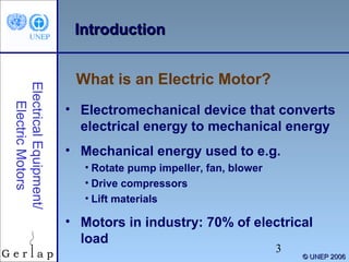
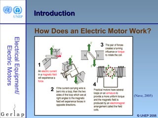
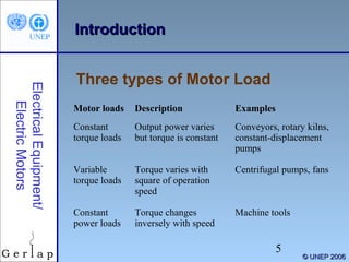
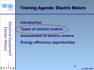
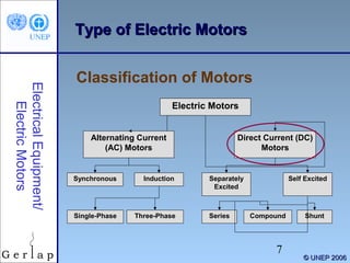
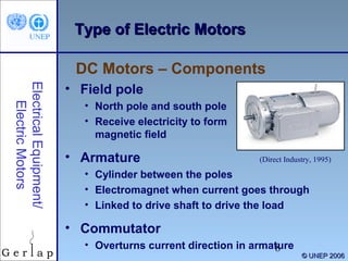
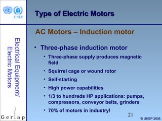
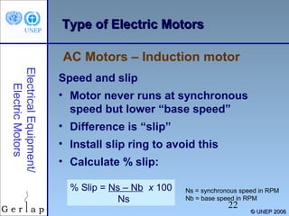
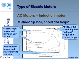
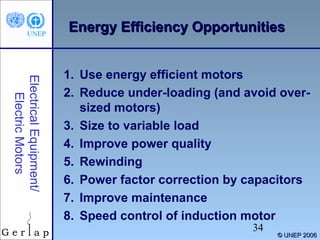
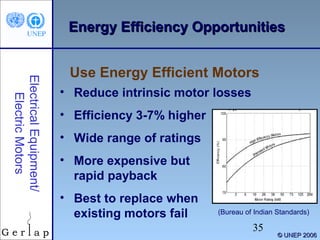
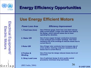
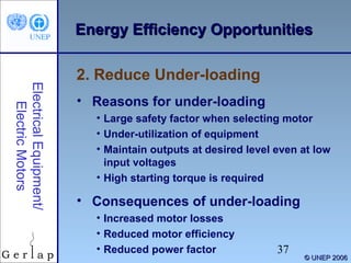
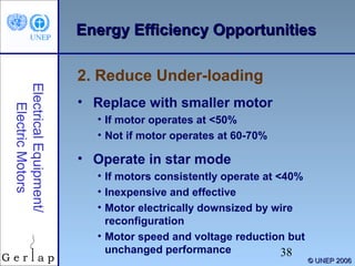
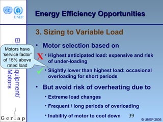
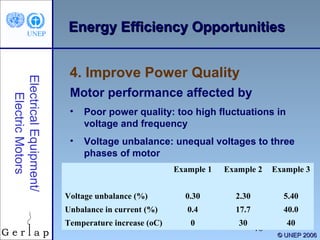
This document provides an overview of electric motors and opportunities for improving their energy efficiency. It begins with an introduction to electric motors, including their basic function and common types such as DC motors, synchronous AC motors, and induction AC motors. It then discusses assessing motor load and efficiency, highlighting factors that influence efficiency like age, load level, and temperature. The document concludes by outlining several energy efficiency opportunities for electric motors, such as using high-efficiency motors, reducing underloading, improving power quality, proper sizing for variable loads, and regular maintenance.
Energy efficient motors use less electricity, run cooler, and often last longer than NEMA (National Electrical Manufacturers Association) B motors of the same size.This presentation is on ' ENERGY EFFICIENT INDUCTION MOTOR ' which is mostly use in industries.
Contents of this presenation entitled 'Introduction of different Energy storage systems used in Electric & Hybrid vehicles' is useful for beginners and students
types of the hybrid vehicle are discussed, series, parallel, complex, series-parallel, micro-hybrid, mild hybrid, full hybrid, and complex hybrid is discussed
The characteristics of a single phase induction motor are identical to three phase induction motor except that single phase induction motor has no inherent starting torque and some special arrangement have to be made for making itself starting.
Though single phase induction motor is not self-starting, we are using it because the three phase supply is not present at everywhere.
The voltage variation as well as power control of inductive load is essential in industrial sector.
The load may any motor or any inductive load.
We can use thyristor to this job but it is easier using TRIAC.
Detailed presentation on the basics of an electric vehicle, comparison of different motors for EV application, comparison of different batteries for EV application, Charging infrastructure for EV in India and a brief on BMS(Battery Management System).
A variable-frequency drive (VFD) or adjustable-frequency drive (AFD), variable-voltage/variable-frequency (VVVF) drive, variable speed drive (VSD), AC drive, micro drive or inverter drive is a type of adjustable-speed drive used in electro-mechanical drive systems to control AC motor speed and torque by varying motor input frequency and voltage.
AC drive, importance of AC drive, different methods of control speed of induction motor and synchonous motor, variable frequency converter, speed control by varying frequency and voltage of stator.
Seminar on Electric vehice pptx, in which we are providing about the electric vehicles , introduction of Electric cars or Vehicles, Hystory of the electric vehicles, components of the electric vehicles, motors, controllers, charger, DC-DC converter, Contractors, batteries of the EVs, power from the electric vehicles, various Evs, Advantages, Disadvantages, conclusion and References.
Why You Should Replace Windows 11 with Nitrux Linux 3.5.0 for enhanced perfor...SOFTTECHHUB
The choice of an operating system plays a pivotal role in shaping our computing experience. For decades, Microsoft's Windows has dominated the market, offering a familiar and widely adopted platform for personal and professional use. However, as technological advancements continue to push the boundaries of innovation, alternative operating systems have emerged, challenging the status quo and offering users a fresh perspective on computing.
One such alternative that has garnered significant attention and acclaim is Nitrux Linux 3.5.0, a sleek, powerful, and user-friendly Linux distribution that promises to redefine the way we interact with our devices. With its focus on performance, security, and customization, Nitrux Linux presents a compelling case for those seeking to break free from the constraints of proprietary software and embrace the freedom and flexibility of open-source computing.
GraphSummit Singapore | The Art of the Possible with Graph - Q2 2024Neo4j
Neha Bajwa, Vice President of Product Marketing, Neo4j
Join us as we explore breakthrough innovations enabled by interconnected data and AI. Discover firsthand how organizations use relationships in data to uncover contextual insights and solve our most pressing challenges – from optimizing supply chains, detecting fraud, and improving customer experiences to accelerating drug discoveries.
GDG Cloud Southlake #33: Boule & Rebala: Effective AppSec in SDLC using Deplo...James Anderson
Effective Application Security in Software Delivery lifecycle using Deployment Firewall and DBOM
The modern software delivery process (or the CI/CD process) includes many tools, distributed teams, open-source code, and cloud platforms. Constant focus on speed to release software to market, along with the traditional slow and manual security checks has caused gaps in continuous security as an important piece in the software supply chain. Today organizations feel more susceptible to external and internal cyber threats due to the vast attack surface in their applications supply chain and the lack of end-to-end governance and risk management.
The software team must secure its software delivery process to avoid vulnerability and security breaches. This needs to be achieved with existing tool chains and without extensive rework of the delivery processes. This talk will present strategies and techniques for providing visibility into the true risk of the existing vulnerabilities, preventing the introduction of security issues in the software, resolving vulnerabilities in production environments quickly, and capturing the deployment bill of materials (DBOM).
Speakers:
Bob Boule
Robert Boule is a technology enthusiast with PASSION for technology and making things work along with a knack for helping others understand how things work. He comes with around 20 years of solution engineering experience in application security, software continuous delivery, and SaaS platforms. He is known for his dynamic presentations in CI/CD and application security integrated in software delivery lifecycle.
Gopinath Rebala
Gopinath Rebala is the CTO of OpsMx, where he has overall responsibility for the machine learning and data processing architectures for Secure Software Delivery. Gopi also has a strong connection with our customers, leading design and architecture for strategic implementations. Gopi is a frequent speaker and well-known leader in continuous delivery and integrating security into software delivery.
In his public lecture, Christian Timmerer provides insights into the fascinating history of video streaming, starting from its humble beginnings before YouTube to the groundbreaking technologies that now dominate platforms like Netflix and ORF ON. Timmerer also presents provocative contributions of his own that have significantly influenced the industry. He concludes by looking at future challenges and invites the audience to join in a discussion.
Enchancing adoption of Open Source Libraries. A case study on Albumentations.AIVladimir Iglovikov, Ph.D.
Presented by Vladimir Iglovikov:
- https://www.linkedin.com/in/iglovikov/
- https://x.com/viglovikov
- https://www.instagram.com/ternaus/
This presentation delves into the journey of Albumentations.ai, a highly successful open-source library for data augmentation.
Created out of a necessity for superior performance in Kaggle competitions, Albumentations has grown to become a widely used tool among data scientists and machine learning practitioners.
This case study covers various aspects, including:
People: The contributors and community that have supported Albumentations.
Metrics: The success indicators such as downloads, daily active users, GitHub stars, and financial contributions.
Challenges: The hurdles in monetizing open-source projects and measuring user engagement.
Development Practices: Best practices for creating, maintaining, and scaling open-source libraries, including code hygiene, CI/CD, and fast iteration.
Community Building: Strategies for making adoption easy, iterating quickly, and fostering a vibrant, engaged community.
Marketing: Both online and offline marketing tactics, focusing on real, impactful interactions and collaborations.
Mental Health: Maintaining balance and not feeling pressured by user demands.
Key insights include the importance of automation, making the adoption process seamless, and leveraging offline interactions for marketing. The presentation also emphasizes the need for continuous small improvements and building a friendly, inclusive community that contributes to the project's growth.
Vladimir Iglovikov brings his extensive experience as a Kaggle Grandmaster, ex-Staff ML Engineer at Lyft, sharing valuable lessons and practical advice for anyone looking to enhance the adoption of their open-source projects.
Explore more about Albumentations and join the community at:
GitHub: https://github.com/albumentations-team/albumentations
Website: https://albumentations.ai/
LinkedIn: https://www.linkedin.com/company/100504475
Twitter: https://x.com/albumentations
Securing your Kubernetes cluster_ a step-by-step guide to success !KatiaHIMEUR1
Today, after several years of existence, an extremely active community and an ultra-dynamic ecosystem, Kubernetes has established itself as the de facto standard in container orchestration. Thanks to a wide range of managed services, it has never been so easy to set up a ready-to-use Kubernetes cluster.
However, this ease of use means that the subject of security in Kubernetes is often left for later, or even neglected. This exposes companies to significant risks.
In this talk, I'll show you step-by-step how to secure your Kubernetes cluster for greater peace of mind and reliability.
Essentials of Automations: The Art of Triggers and Actions in FMESafe Software
In this second installment of our Essentials of Automations webinar series, we’ll explore the landscape of triggers and actions, guiding you through the nuances of authoring and adapting workspaces for seamless automations. Gain an understanding of the full spectrum of triggers and actions available in FME, empowering you to enhance your workspaces for efficient automation.
We’ll kick things off by showcasing the most commonly used event-based triggers, introducing you to various automation workflows like manual triggers, schedules, directory watchers, and more. Plus, see how these elements play out in real scenarios.
Whether you’re tweaking your current setup or building from the ground up, this session will arm you with the tools and insights needed to transform your FME usage into a powerhouse of productivity. Join us to discover effective strategies that simplify complex processes, enhancing your productivity and transforming your data management practices with FME. Let’s turn complexity into clarity and make your workspaces work wonders!
DevOps and Testing slides at DASA ConnectKari Kakkonen
My and Rik Marselis slides at 30.5.2024 DASA Connect conference. We discuss about what is testing, then what is agile testing and finally what is Testing in DevOps. Finally we had lovely workshop with the participants trying to find out different ways to think about quality and testing in different parts of the DevOps infinity loop.
Unlocking Productivity: Leveraging the Potential of Copilot in Microsoft 365, a presentation by Christoforos Vlachos, Senior Solutions Manager – Modern Workplace, Uni Systems
In the rapidly evolving landscape of technologies, XML continues to play a vital role in structuring, storing, and transporting data across diverse systems. The recent advancements in artificial intelligence (AI) present new methodologies for enhancing XML development workflows, introducing efficiency, automation, and intelligent capabilities. This presentation will outline the scope and perspective of utilizing AI in XML development. The potential benefits and the possible pitfalls will be highlighted, providing a balanced view of the subject.
We will explore the capabilities of AI in understanding XML markup languages and autonomously creating structured XML content. Additionally, we will examine the capacity of AI to enrich plain text with appropriate XML markup. Practical examples and methodological guidelines will be provided to elucidate how AI can be effectively prompted to interpret and generate accurate XML markup.
Further emphasis will be placed on the role of AI in developing XSLT, or schemas such as XSD and Schematron. We will address the techniques and strategies adopted to create prompts for generating code, explaining code, or refactoring the code, and the results achieved.
The discussion will extend to how AI can be used to transform XML content. In particular, the focus will be on the use of AI XPath extension functions in XSLT, Schematron, Schematron Quick Fixes, or for XML content refactoring.
The presentation aims to deliver a comprehensive overview of AI usage in XML development, providing attendees with the necessary knowledge to make informed decisions. Whether you’re at the early stages of adopting AI or considering integrating it in advanced XML development, this presentation will cover all levels of expertise.
By highlighting the potential advantages and challenges of integrating AI with XML development tools and languages, the presentation seeks to inspire thoughtful conversation around the future of XML development. We’ll not only delve into the technical aspects of AI-powered XML development but also discuss practical implications and possible future directions.
GraphRAG is All You need? LLM & Knowledge GraphGuy Korland
Guy Korland, CEO and Co-founder of FalkorDB, will review two articles on the integration of language models with knowledge graphs.
1. Unifying Large Language Models and Knowledge Graphs: A Roadmap.
https://arxiv.org/abs/2306.08302
2. Microsoft Research's GraphRAG paper and a review paper on various uses of knowledge graphs:
https://www.microsoft.com/en-us/research/blog/graphrag-unlocking-llm-discovery-on-narrative-private-data/
UiPath Test Automation using UiPath Test Suite series, part 5DianaGray10
Welcome to UiPath Test Automation using UiPath Test Suite series part 5. In this session, we will cover CI/CD with devops.
Topics covered:
CI/CD with in UiPath
End-to-end overview of CI/CD pipeline with Azure devops
Speaker:
Lyndsey Byblow, Test Suite Sales Engineer @ UiPath, Inc.
Sudheer Mechineni, Head of Application Frameworks, Standard Chartered Bank
Discover how Standard Chartered Bank harnessed the power of Neo4j to transform complex data access challenges into a dynamic, scalable graph database solution. This keynote will cover their journey from initial adoption to deploying a fully automated, enterprise-grade causal cluster, highlighting key strategies for modelling organisational changes and ensuring robust disaster recovery. Learn how these innovations have not only enhanced Standard Chartered Bank’s data infrastructure but also positioned them as pioneers in the banking sector’s adoption of graph technology.
TO THE TRAINER
This PowerPoint presentation can be used to train people about the basics of electric motors. The information on the slides is the minimum information that should be explained. The trainer notes for each slide provide more detailed information, but it is up to the trainer to decide if and how much of this information is presented also.
Additional materials that can be used for the training session are available on www.energyefficiencyasia.org under “Energy Equipment” and include:
Textbook chapter on this energy equipment that forms the basis of this PowerPoint presentation but has more detailed information
Quiz – ten multiple choice questions that trainees can answer after the training session
Workshop exercise – a practical calculation related to this equipment
Option checklist – a list of the most important options to improve energy efficiency of this equipment
Company case studies – participants of past courses have given the feedback that they would like to hear about options implemented at companies for each energy equipment. More than 200 examples are available from 44 companies in the cement, steel, chemicals, ceramics and pulp & paper sectors
An electric motor is an electromechanical device that converts electrical energy to mechanical energy. The mechanical energy can be used to perform work such as rotating a pump impeller, fan, blower, driving a compressor, lifting materials etc.
It is estimated that about 70% of the total electrical load is accounted by motors only. That is why electric motors are termed as “Work Horse” in an industry.
The general working mechanism is the same for all motors and shown in the figure
An electric current in a magnetic field will experience a force.
If the current carrying wire is bent into a loop, then the two sides of the loop, which are at right angle to the magnetic field, will experience forces in opposite directions.
The pair of forces creates a turning torque to rotate the coil. (note: a “torque” is the force that causes the rotation)
Practical motors have several loops on an armature to provide a more uniform torque and the magnetic field is produced by electromagnet arrangement called the field coils
In understanding a motor it is important to understand what a motor load means. Load refers to the torque output and corresponding speed required. Loads can generally be categorized into three groups:
Constant torque loads are those for which the output power requirement may vary with the speed of operation but the torque does not vary. Conveyors, rotary kilns, and constant-displacement pumps are typical examples of constant torque loads.
Variable torque loads are those for which the torque required varies with the speed of operation. Centrifugal pumps and fans are typical examples of variable torque loads (torque varies as the square of the speed).
Constant power loads are those for which the torque requirements typically change inversely with speed. Machine tools are a typical example of a constant power load
Motors are categorized in a number of types based on the input supply, construction and principle of operation. We will start at looking at various forms of the DC motor such as shunt and series, followed by the AC motors including synchronous and induction motors.
Direct-Current motors, as the name implies, use a direct-unidirectional current. A DC motor is shown in the figure and has three main components:
Field pole. Simply put, the interaction of two magnetic fields causes the rotation in a DC motor. The DC motor has field poles that are stationary and an armature that turns on bearings in the space between the field poles. A simple DC motor has two field poles: a north pole and a south pole. The magnetic lines of force extend across the opening between the poles from north to south. For larger or more complex motors there are one or more electromagnets. These electromagnets receive electricity from an outside power source and serve as the field structure.
Armature. When current goes through the armature, it becomes an electromagnet. The armature, cylindrical in shape, is linked to a drive shaft in order to drive the load. For the case of a small DC motor, the armature rotates in the magnetic field established by the poles, until the north and south poles of the magnets change location with respect to the armature. Once this happens, the current is reversed to switch the south and north poles of the armature.
Commutator. This component is found mainly in DC motors. Its purpose is to overturn the direction of the electric current in the armature. The commutator also aids in the transmission of current between the armature and the power source.
The main advantage of DC motors is speed control, which does not affect the quality of power supply. It can be controlled by adjusting:
the armature voltage – increasing the armature voltage will increase the speed
the field current – reducing the field current will increase the speed.
DC motors are available in a wide range of sizes, but their use is generally restricted to a few low speed, low-to-medium power applications like machine tools and rolling mills because of problems with mechanical commutation at large sizes. Also, they are restricted for use only in clean, non-hazardous areas because of the risk of sparking at the brushes.
DC motors are also expensive relative to AC motors.
The relationship between speed, field flux and armature voltage is shown in the following equation:
Back electromagnetic force: E = KN
Torque: T = KIa
Where:
E = electromagnetic force developed at armature terminal (volt)
= field flux which is directly proportional to field current
N = speed in RPM (revolutions per minute)
T = electromagnetic torque
Ia = armature current
K = an equation constant
If field is supplied from a separate source it is called as separately excited DC motor.
(Click once) In a shunt motor, the field winding (shunt field) is connected in parallel with the armature winding (A) as shown in the. The total line current is therefore the sum of field current and armature current
The following can be said about the speed of shunt motors:
(Click once) The speed is practically constant independent of the load (up to a certain torque after which speed decreases) and therefore suitable for commercial applications with a low starting load, such as machine tools
(Click once) Speed can be controlled by either inserting a resistance in series with the armature (decreasing speed) or by inserting resistance in the field current (increasing speed)
In a series motor, the field winding (shunt field) is connected in series with the armature winding (A) as shown in the figure. The field current is therefore equal to the armature current.
(Click once) The following can be said about the speed of a series motor
Speed is restricted to 5000 RPM
It must be avoided to run a series motor with no load because the motor will accelerate uncontrollably
(Click once) Series motors are suited for applications requiring a high starting torque, such as cranes and hoists
A DC compound motor is a combination of shunt and series motor. In a compound motor, the field winding (shunt field) is connected in parallel and in series with the armature winding (A) as shown in the figure.
(Click once) For this reason this motor has a good starting torque and a stable speed.
(Click once) The higher the percentage of compounding (i.e. percentage of field winding connected in series), the higher the starting torque this motor can handle.
(Click once) For example, compounding of 40-50% makes the motor suitable for hoists and cranes, but standard compound motors (12%) are not.
We will now take a closer look at the AC motors.
Alternating current (AC) motors use an electrical current, which reverses its direction at regular intervals.
An AC motor has two basic electrical parts: a "stator" and a "rotor". The stator is in the stationary electrical component. The rotor is the rotating electrical component, which in turn rotates the motor shaft.
The main advantage of DC motors over AC motors is that speed is more difficult to control for AC motors. To compensate for this, AC motors can be equipped with variable frequency drives but the improved speed control comes together with a reduced power quality.
There are two types of AC motors: synchronous (see figure) and induction. The main difference between the synchronous motor and the induction motor is that the rotor of the synchronous motor travels at the same speed as the rotating magnetic field.
A synchronous motor is an AC motor, which runs at constant speed fixed by frequency of the system.
It requires direct current (DC) for excitation and has low starting torque, and synchronous motors are therefore suited for applications that start with a low load, such as air compressors, frequency changes and motor generators.
Synchronous motors are able to improve the power factor of a system, which is why they are often used in systems that use a lot of electricity.
This motor rotates at a synchronous speed, which is given by the following equation
Ns = 120 f / P
Where:
f = frequency of the supply frequency
P= number of poles
Induction motors are the most common motors used for various equipments in industry.
Their popularity is due to
their simple design,
they are inexpensive (half or less of the cost of a DC motor)
High power to weight ratio (about twice that of a DC motor)
easy to maintain
can be directly connected to an AC power source
An induction motor has two main electrical components as shown in the figure
Rotor. Induction motors use two types of rotors:
A squirrel-cage rotor consists of thick conducting bars embedded in parallel slots. These bars are short-circuited at both ends by means of short-circuiting rings.
A wound rotor has a three-phase, double-layer, distributed winding. It is wound for as many poles as the stator. The three phases are wired internally and the other ends are connected to slip-rings mounted on a shaft with brushes resting on them.
Stator. The stator is made up of a number of stampings with slots to carry three-phase windings. It is wound for a definite number of poles. The windings are geometrically spaced 120 degrees apart
Induction motors work as follows:
Electricity is supplied to the stator, which generates a magnetic field.
This magnetic field moves at synchronous speed around the rotor, which in turn induces a current in the rotor.
The rotor current produces a second magnetic field, which tries to oppose the stator magnetic field, and this causes the rotor to rotate.
Induction motors can be classified into two main groups: single-phase and three-phase induction motors
Single-phase induction motors. These only have one stator winding, operate with a single-phase power supply, have a squirrel cage rotor, and require a device to get the motor started. This is by far the most common type of motor used in household appliances, such as fans, washing machines and clothes dryers, and for applications for up to 3 to 4 horsepower.
Induction motors can be classified into two main groups:
Single-phase induction motors. These only have one stator winding, operate with a single-phase power supply, have a squirrel cage rotor, and require a device to get the motor started. This is by far the most common type of motor used in household appliances, such as fans, washing machines and clothes dryers, and for applications for up to 3 to 4 horsepower.
Three-phase induction motors. The rotating magnetic field is produced by the balanced three-phase supply. These motors have high power capabilities, can have squirrel cage or wound rotors (although 90% have a squirrel cage rotor), and are self-starting. It is estimated that about 70% of motors in industry are of this type, are used in, for example, pumps, compressors, conveyor belts, heavy-duty electrical networks, and grinders. They are available in 1/3 to hundreds of horsepower ratings.
In practice however, the motor never runs at synchronous speed but at a lower “base speed”. The difference between these two speeds is the “slip”, which increases with higher loads. Slip only occurs in all induction motors. To avoid slip, a slip ring can be installed, and these motors are called “slip ring motors”. The following equation can be used to calculate the percentage slip
% Slip = Ns – Nb x 100
Ns
Where:
Ns = synchronous speed in RPM
Nb = base speed in RPM
The figure shows the typical torque-speed curve of a three-phase AC induction motor with a fixed current. When the motor:
(Click once) Starts there is a high starting current and low torque (“pull-up torque”).
(Click once) Reaches 80% of the full speed, the torque is at its highest level (“pull-out torque”) and the current begins to drop.
(Click once) Is at full speed, or synchronous speed, the torque and stator current drop to zero.
The efficiency of a motor can be defined as “the ratio of a motor’s useful power output to its total power output.”
Motors convert electrical energy to mechanical energy to serve a certain load. In this process, energy is lost as shown in the figure.
The efficiency of a motor is determined by intrinsic losses that can be reduced only by changes in motor design and operating condition. Losses can vary from approximately two percent to 20 percent.
Factors that influence motor efficiency include:
Age. New motors are more efficient
Capacity. As with most equipment, motor efficiency increases with the rated capacity
Speed. Higher speed motors are usually more efficient
Type. For example, squirrel cage motors are normally more efficient than slip-ring motors
Temperature. Totally-enclosed fan-cooled (TEFC) motors are more efficient than screen-protected drip-proof (SPDP) motors
Rewinding of motors can result in reduced efficiency
Load, as described below
There is a clear link between the motor’s efficiency and the load. Manufacturers design motors to operate at a 50-100% load and to be most efficient at a 75% load.
But once the load drops below 50% the efficiency decreases rapidly as shown in the figure. Operating motors below 50% of rated loads has a similar, but less significant, impact on the power factor. High motor efficiencies and power factor close to 1 are desirable for an efficient operation and for keeping costs down of the entire plant and not just the motor.
Because the efficiency of a motor is difficult to assess under normal operating conditions, the motor load can be measured as an indicator of the motor’s efficiency. As loading increases, the power factor and the motor efficiency increase to an optimum value at around full load.
The following equation is used to determine the load:
Load = Pi x HP x 0.7457
Where,
= Motor operating efficiency in %
HP= Nameplate rated horse power
Load= Output power as a % of rated power
Pi= Three phase power in kW
There are three methods to determine the motor load for motors operating individually:
Input power measurement. This method calculates the load as the ratio between the input power (measured with a power analyzer) and the rated power at 100 % loading.
Line current measurement. The load is determined by comparing the measured amperage (measured with a power analyzer) with the rated amperage. This method is used when the power factor is not known and only the amperage value is available. It is also recommended to use this method when the percentage loading is less than 50%
Slip method. The load is determined by comparing the slip measured when the motor is operating with the slip for the motor at full load. The accuracy of this method is limited but it can be used with the use of a tachometer only (no power analyzer is needed).
Because the input power measurement is the most common method used, only this method is described for three-phase motors.
When available, “direct-read” power measurements are used to estimate motor part-load. The measurements can be used in three different formula. (click once) To begin with, one can use this equation to determine the input power.
(click once). Step 2. Determine the rated power by taking the nameplate value or by using the equation
(click once) Step 3. Determine the percentage load using
The results of a motor load survey can be divided into different categories with recommended actions.
(click once) Motors that are significantly oversized and underloaded should be replaced with more efficient, properly sized models at the next opportunity, such as scheduled plant downtime.
(click once) Motors that are moderately oversized and underloaded should be replaced with more efficient, properly sized models when they fail.
(click once) Motors that are properly sized but standard efficiency these should be replaced most of these with energy-efficient models when they fail. The cost effectiveness of an energy-efficient motor purchase depends on the number of hours the motor is used, the price of electricity, and the price premium of buying an energy-efficient motor.
We will go through eight areas to improve the energy efficiency of motors
High efficiency motors have been designed specifically to increase operating efficiency compared to standard motors. Design improvements focus on reducing intrinsic motor losses (is further explained on next slide)
Efficiencies are 3% to 7% higher compared with standard motors as shown in the figure.
Energy efficient motors cover a wide range of ratings and the full load. As a result of the modifications to improve performance, the costs of energy efficient motors are higher than those of standard motors.
The higher cost will often be paid back rapidly through reduced operating costs, particularly in new applications or end-of-life motor replacements.
But replacing existing motors that have not reached the end of their useful life with energy efficient motors may not always be financially feasible, and therefore it is recommended to only replace these with energy efficiency motors when they fail.
Energy-efficient motors have design improvements that specifically seek to increase operating efficiency for the five power loss areas: fixed, stator, rotor, friction & winding, and stray load loss (note: these were explained in earlier slide)
(It is suggested to give one example only) This table depicts the energy efficiency areas achieved incase of energy efficient motors. For example, looking at the power loss area “iron”, the efficiency improvement is use of thinner gauge, lower loss core steel reduces eddy current losses. Longer core adds more steel to the design, which reduces losses due to lower operating flux densities.
Under-loading is probably the most common cause of inefficiencies for several reasons:
Equipment manufacturers tend to use a large safety factor when selecting the motor.
Equipment is often under-utilized. For example, machine tool equipment manufacturers provide for a motor rated for the full capacity load of the equipment. In practice, the user may rarely need this full capacity, resulting in under-loaded operation most of the time.
Large motors are selected to enable the output to be maintained at the desired level even when input voltages are abnormally low.
Large motor are selected for applications requiring a high starting torque but where a smaller motor that is designed for high torque would have been more suitable.
(Click once) Under-loading increases motor losses and reduces motor efficiency and the power factor.
Replace with smaller motors
When replacing an oversized motor with a smaller motor, it is also important to consider the potential efficiency gain. Larger motors namely have inherently higher rated efficiencies than smaller motors. Therefore, the replacement of motors operating at 60 – 70% of capacity or higher is generally not recommended. On the other hand there are no rigid rules governing motor selection and the savings potential needs to be evaluated on a case-by-case basis. For example, if a smaller motor is an energy efficient motor and the existing motor not, then the efficiency could improve.
(Click once) Operate in star mode (from delta mode)
For motors that consistently operate at loads below 40% of the rated capacity
Inexpensive and effective measure.
Motor is electrically downsized: involves re-configuring the wiring of the three phases of power input at the terminal box.
Leads to a voltage reduction by factor ‘√3’, but performance characteristics as a function of load remain unchanged. Thus, motors in star mode have a higher efficiency and power factor when in full-load operation than partial load operation in the delta mode.
Possible only for applications where the torque-to-speed requirement is lower at reduced load. Should be avoided if the motor is connected to a production facility with an output that is related to the motor speed (as the motor speed reduces in star mode).
Motor selection based on
the highest anticipated load makes the motor more expensive as the motor would operate at full capacity for short periods only, and it carries the risk of motor under-loading.
the load duration curve of a particular application is a better alternative. This means that the selected motor rating is slightly lower than the highest anticipated load and would occasionally overload for a short period of time. (Click once) This is possible as manufacturers design motors with a service factor (usually 15% above the rated load) to ensure that running motors above the rated load once in a while will not cause significant damage.
(Click once) The biggest risk is overheating of the motor, which adversely affects the motor life and efficiency and increases operating costs. Overheating can occur with:
Extreme load changes, such as frequent starts / stops, or high initial loads
Frequent and/or long periods of overloading
Limited ability for the motor to cool down, for example at high altitudes, in hot environments or when motors are enclosed or dirty
A criteria in selecting the motor rating is therefore that the weighted average temperature rise over the actual operating cycle should not be greater than the temperature rise under continuous full-load operation (100%).
Where loads vary substantially with time, speed control methods can be applied in addition to proper motor sizing (will be explained later)
Motor performance is affected considerably by the quality of input power, which is determined by the actual volts and frequency compared to rated values. Fluctuation in voltage and frequency much larger than the accepted values has detrimental impacts on motor performance.
Voltage unbalance can be even more detrimental to motor performance and occurs when the voltages in the three phases of a three-phase motor are not equal.
Several factors can affect voltage balance: single-phase loads on any one phase, different cable sizing, or faulty circuits. An unbalanced system increases distribution system losses and reduces motor efficiency.
An example of the effect of voltage unbalance on motor performance is shown in the table. Give one example: small voltage unbalances are acceptable but, for example, a voltage unbalance of 5.4% results in a temperature increase of 40oC!!!
The voltage of each phase in a three-phase system should be of equal magnitude, symmetrical, and separated by 120°. Phase balance should be within 1% to avoid derating of the motor and voiding of manufacturers’ warranties.
Voltage unbalance can be minimized by:
Balancing any single phase loads equally among all the three phases
Segregating any single phase loads which disturb the load balance and feed them from a separate line / transformer
It is common practice in industry to rewind burnt-out motors. The number of rewound motors in some industries exceeds 50% of the total number of motors. Careful rewinding can sometimes maintain motor efficiency at previous levels, but in most cases results in efficiency losses.
Rewinding can affect a number of factors that contribute to deteriorated motor efficiency: winding and slot design, winding material, insulation performance, and operating temperature.
When rewinding motors it is important to consider the following:
Use a firm that ISO 9000 certified or is member of an Electrical Apparatus Service Association.
Motors less than 40 HP in size and more than 15 years old (especially previously rewound motors) often have efficiencies significantly lower than currently available energy-efficient models. It is usually best to replace them. It is almost always best to replace non-specialty motors under 15 HP.
If the rewind cost exceeds 50% to 65% of a new energy-efficient motor price, buy the new motor. Increased reliability and efficiency should quickly recover the price premium.
(Optional) The impact of rewinding on motor efficiency and power factor can be easily assessed if the no-load losses of a motor are known before and after rewinding. Information of no-load losses and no-load speed can be found in documentation of motors obtained at the time of purchase. An indicator of the success of rewinding is the comparison of no load current and stator resistance per phase of a rewound motor with the original no-load current and stator resistance at the same voltage.
As noted earlier, induction motors are characterized by power factors less than one, leading to lower overall efficiency (and higher overall operating cost) associated with a plant’s electrical system.
Capacitors connected in parallel (shunted) with the motor are often used to improve the power factor. The capacitor will not improve the power factor of the motor itself but of the starter terminals where power is generated or distributed. The benefits of power factor correction include
reduced kVA demand (and hence reduced utility demand charges),
reduced I2R losses in cables upstream of the capacitor (and hence reduced energy charges),
reduced voltage drop in the cables (leading to improved voltage regulation),
and an increase in the overall efficiency of the plant electrical system.
The size of capacitor depends upon the no-load reactive kVA (kVAR) drawn by the motor. This size should not exceed 90% of the no-load kVAR of the motor, because higher capacitors could result in too high voltages and motor burn-outs. The kVAR of the motor can only be determined by no-load testing of the motor. An alternative is to use typical power factors of standard motors to determine the capacitor size.
More information on the power factor and capacitors is given in the chapter Electricity.
Poor maintenance can cause deterioration in motor efficiency over time and lead to unreliable operation.
Appropriate maintenance is needed to maintain motor performance. A checklist of good maintenance practices would include: (Depending on time, give one or two examples only)
Inspect motors regularly for wear in bearings and housings (to reduce frictional losses) and for dirt/dust in motor ventilating ducts (to ensure proper heat dissipation)
Check load conditions to ensure that the motor is not over or under loaded. A change in motor load from the last test indicates a change in the driven load, the cause of which should be understood
Lubricate appropriately. Manufacturers generally give recommendations for how and when to lubricate their motors. Inadequate lubrication can cause problems, as noted above. Over-lubrication can also create problems, e.g. excess oil or grease from the motor bearings can enter the motor and saturate the motor insulation, causing premature failure or creating a fire risk
Check periodically for proper alignment of the motor and the driven equipment. Improper alignment can cause shafts and bearings to wear quickly, resulting in damage to both the motor and the driven equipment
Ensure that supply wiring and terminal box are properly sized and installed. Inspect regularly the connections at the motor and starter to be sure that they are clean and tight
Provide adequate ventilation and keep motor cooling ducts clean to help dissipate heat to reduce excessive losses. The life of the insulation in the motor would also be longer: for every 10oC increase in motor operating temperature over the recommended peak, the time before rewinding would be needed is estimated to be halved
Because an induction motor is an asynchronous motor, changing the supply frequency can vary the speed. The control strategy for a particular motor will depend on a number of factors including investment cost, load reliability and any special control requirements. This requires a detailed review of the load characteristics, historical data on process flows, features required of the speed control system, the electricity tariffs and the investment costs.
We will go through four ways to control motor speed: multiple speed motors, wound rotor AC motor drives, variable speed drives, direct current drives
Multi-speed motors
Motors can be wound such that two speeds, in the ratio of 2:1, can be obtained. Motors can also be wound with two separate windings, each giving two operating speeds and thus a total of four speeds. Multi-speed motors can be designed for applications involving constant torque, variable torque, or for constant output power. Multi-speed motors are suitable for applications that require limited speed control (two or four fixed speeds instead of continuously variable speed).
Wound rotor AC motor drives (slip ring induction motors)
Wound rotor motor drives use a specially constructed motor to accomplish speed control. The motor rotor is constructed with windings that are lifted out of the motor through slip rings on the motor shaft. These windings are connected to a controller, which places variable resistors in series with the windings.
The torque performance of the motor can be controlled using these variable resistors.
Wound rotor motors are most common in the range of 300 HP and above.
Variable speed drives (VSDs)
Variable speed drives (VSDs) are also called inverters and can change the speed of a motor. They are available in a range several kW to 750 kW. They are designed to operate standard induction motors and can therefore be easily installed in an existing system. Inverters are often sold separately because the motor may already be in place, but can also be purchased together with a motor.
When loads vary, VSDs or two-speed motors can often reduce electrical energy consumption in centrifugal pumping and fan applications by 50% or more.
The basic drive consists of the inverter itself which converts the 50 Hz incoming power to a variable frequency and variable voltage. The variable frequency will control the motor speed.
There are three major types of inverters designs available today. These are known as Current Source Inverters (CSI), Variable Voltage Inverters (VVI), and Pulse Width Modulated Inverters (PWM).
Direct Current Drives
The DC drive technology is the oldest form of electrical speed control. The drive system consists of a DC motor and a controller.
The motor is constructed with an armature and field windings.
The field windings require a DC excitation for motor operation, usually with a constant level voltage from the controller.
The armature connections are made through a brush and commutator assembly. The speed of the motor is directly proportional to the applied voltage.
The controller is a phase-controlled bridge rectifier with logic circuits to control the DC voltage delivered to the motor armature.
Speed control is achieved by regulating the armature voltage to the motor. Often a tacho-generator is included to achieve good speed regulation. The tacho-generator would be mounted onto the motor to produce a speed feedback signal that is used inside the controller.