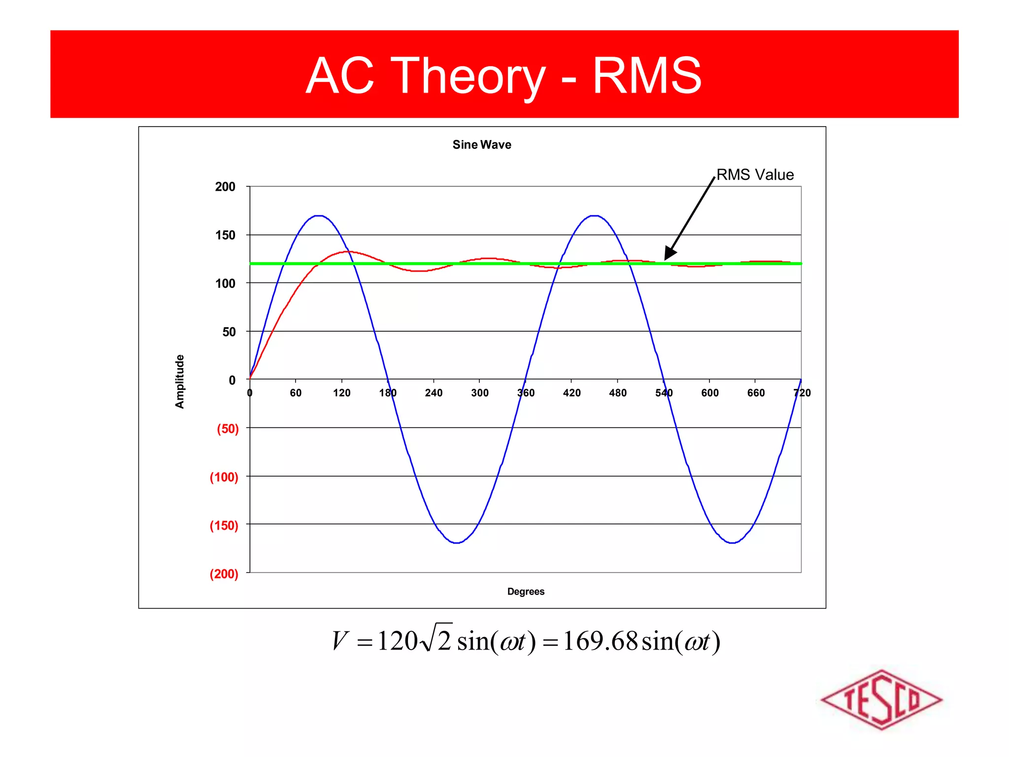
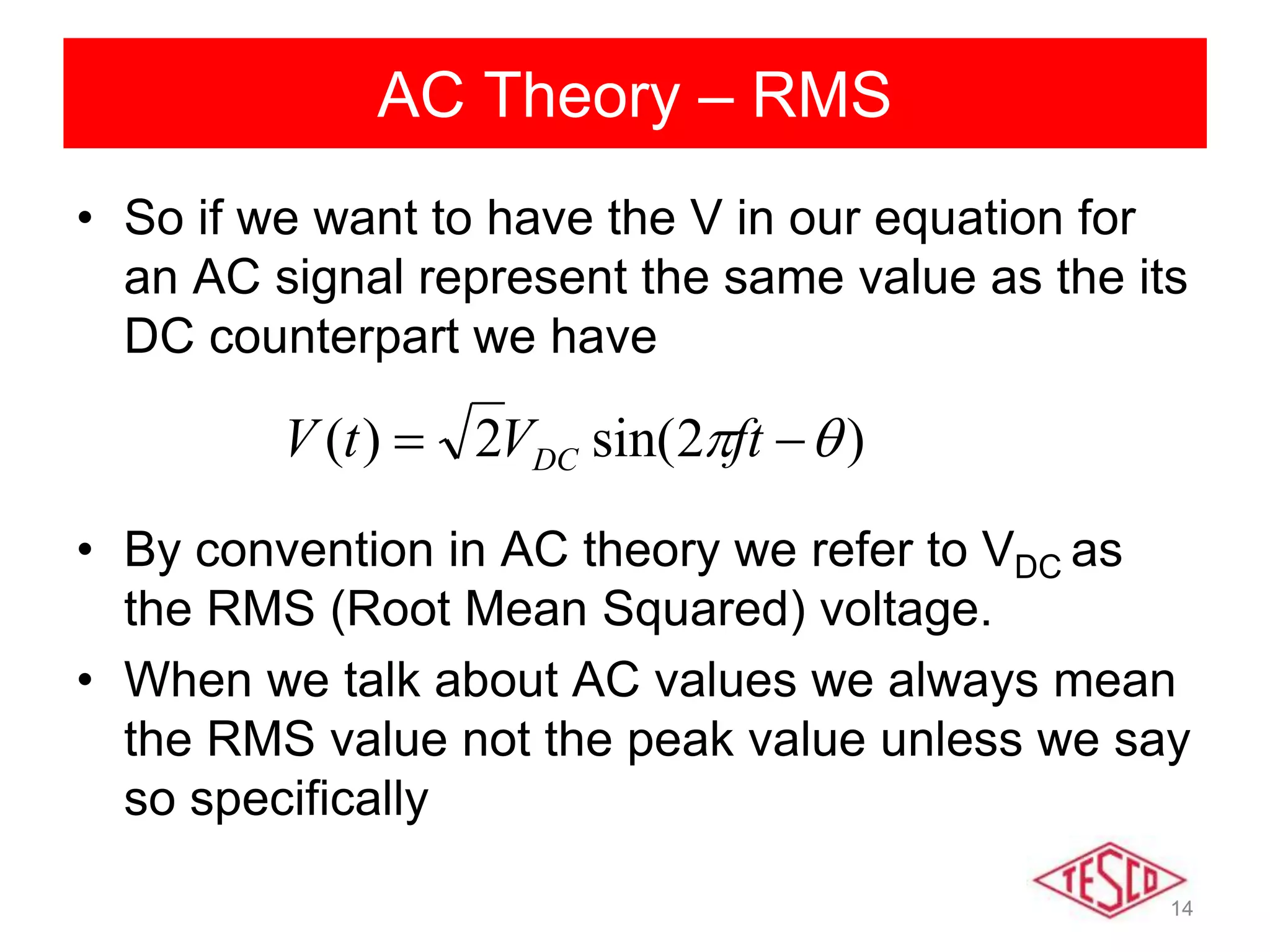
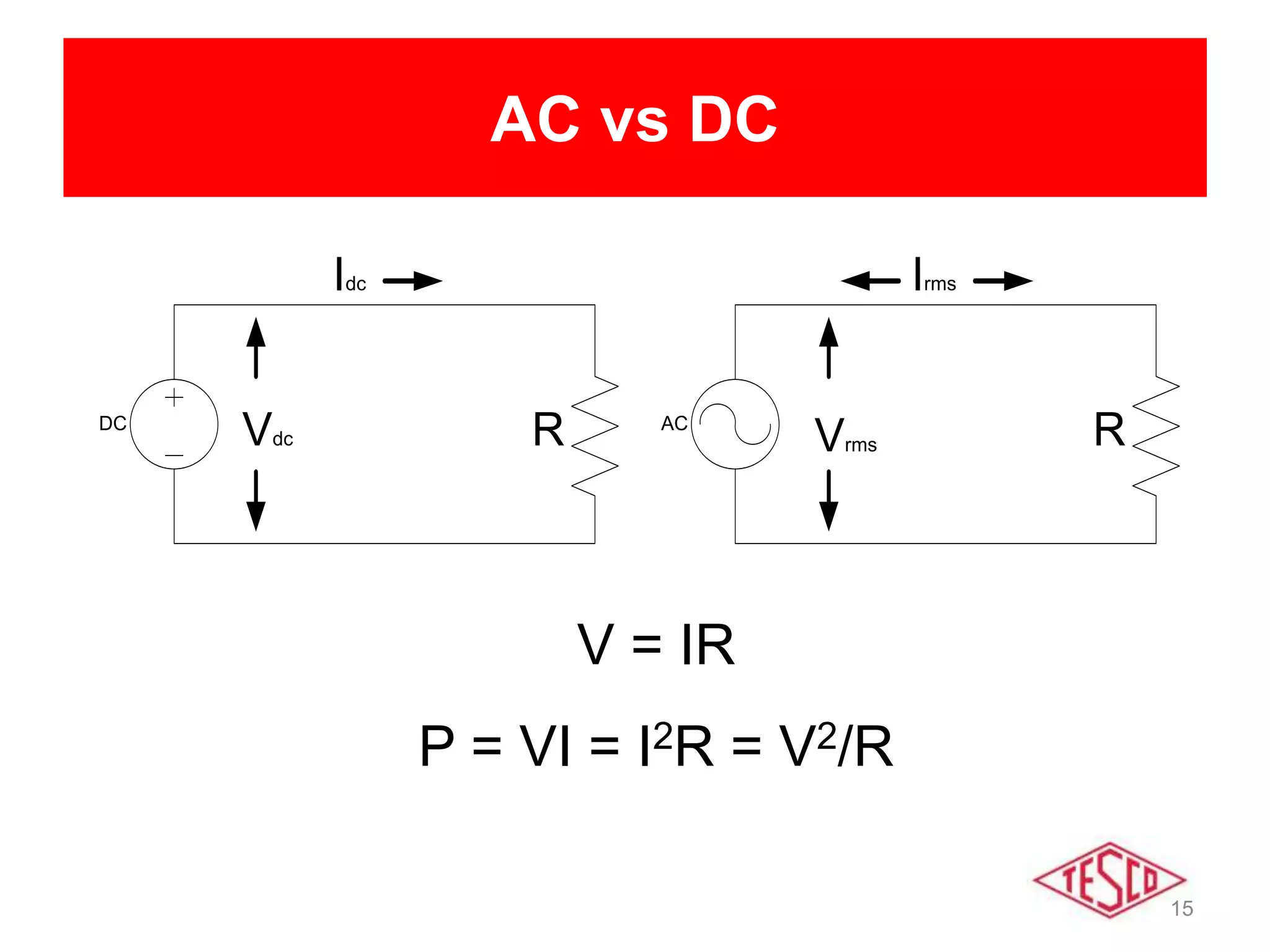
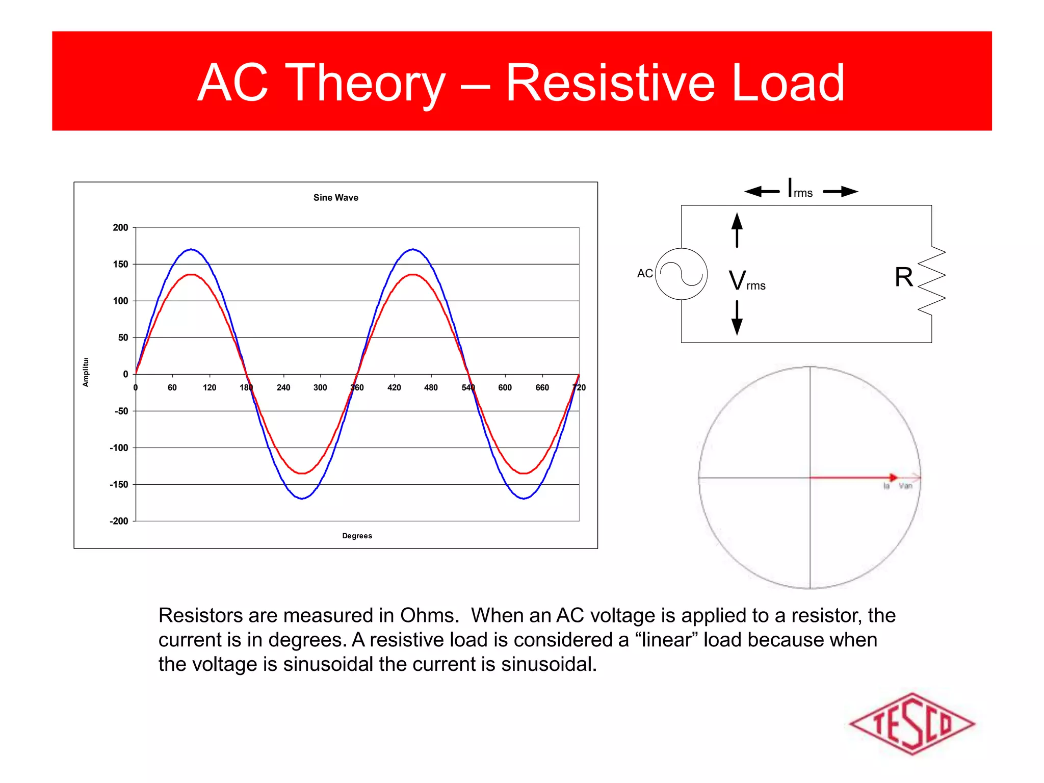
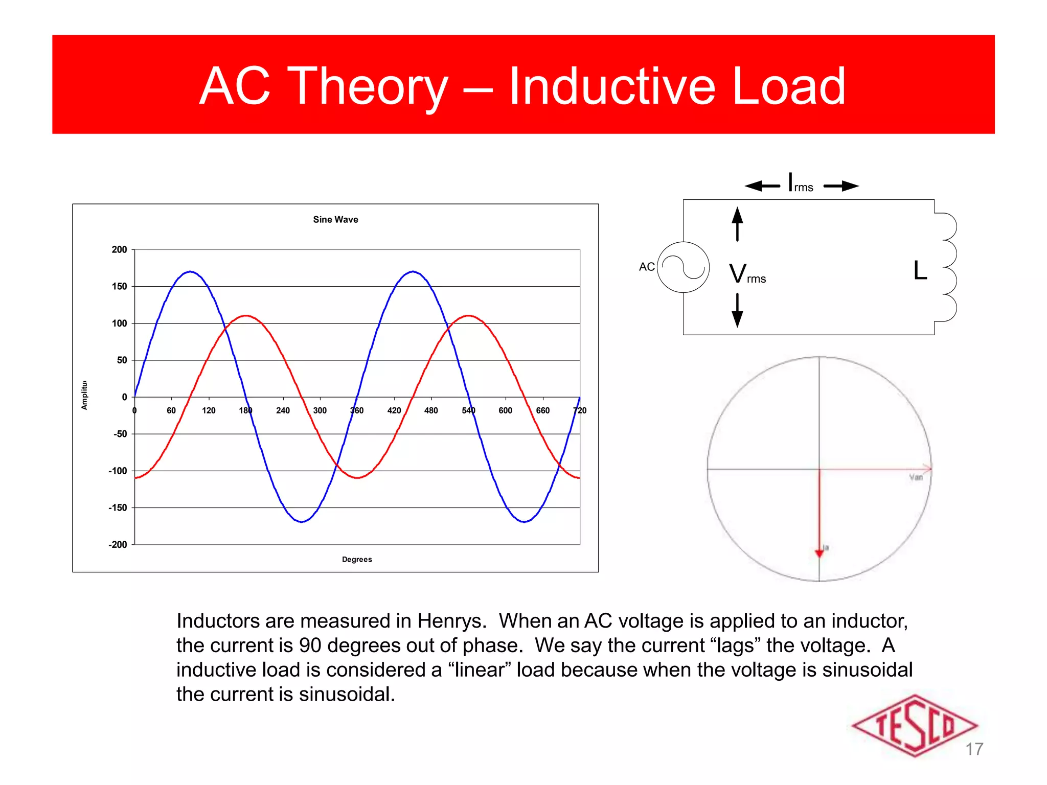
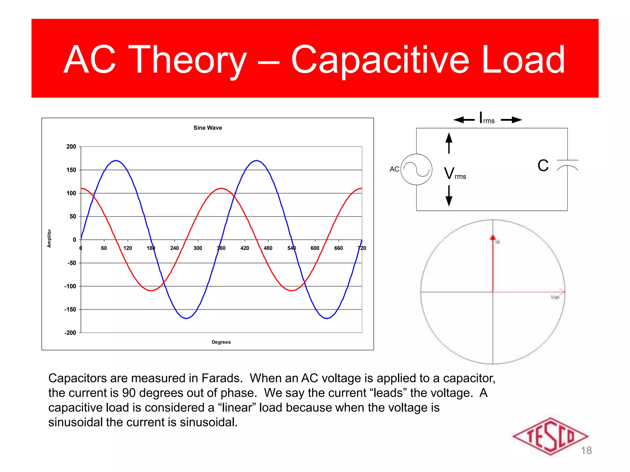
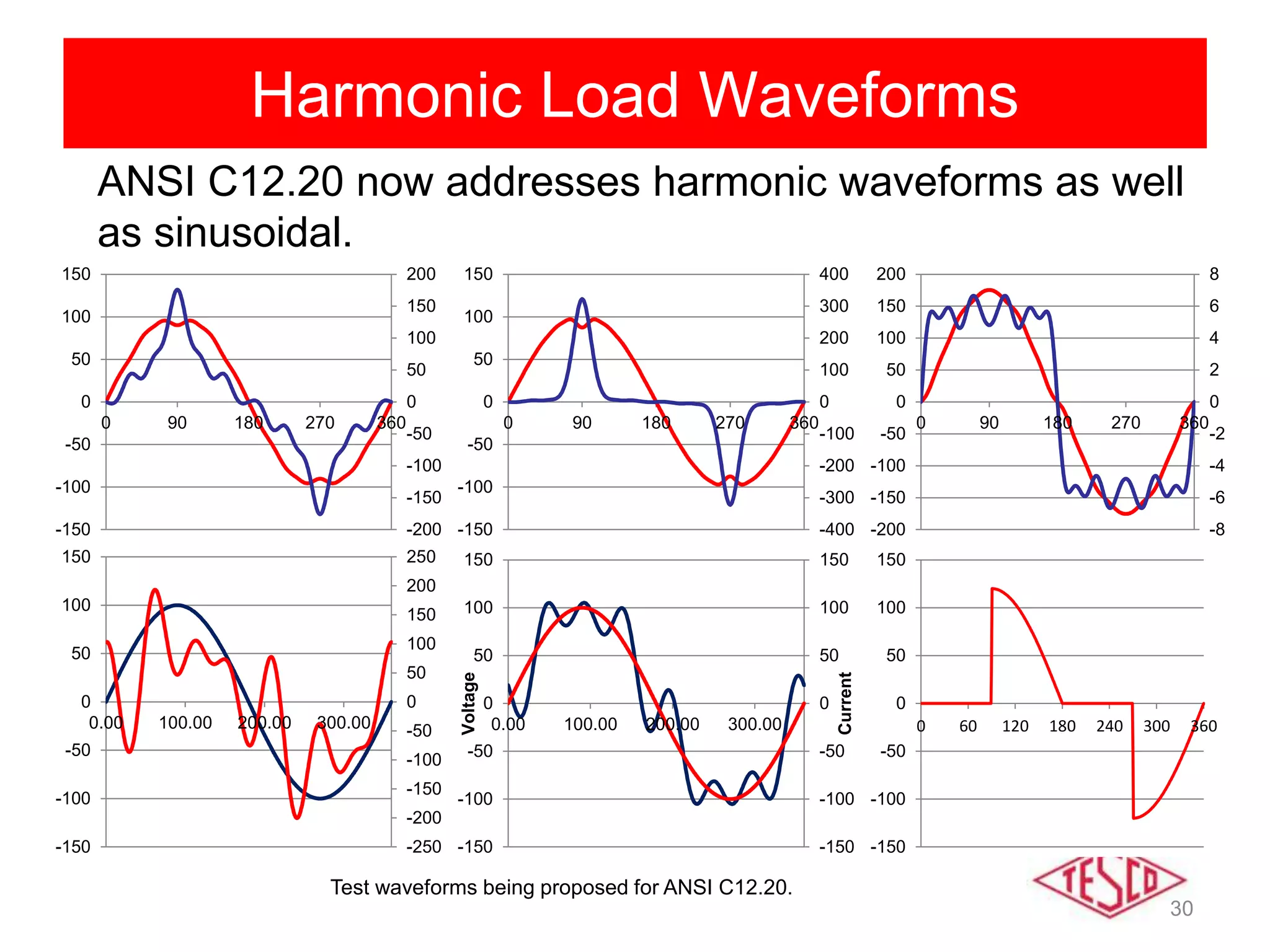
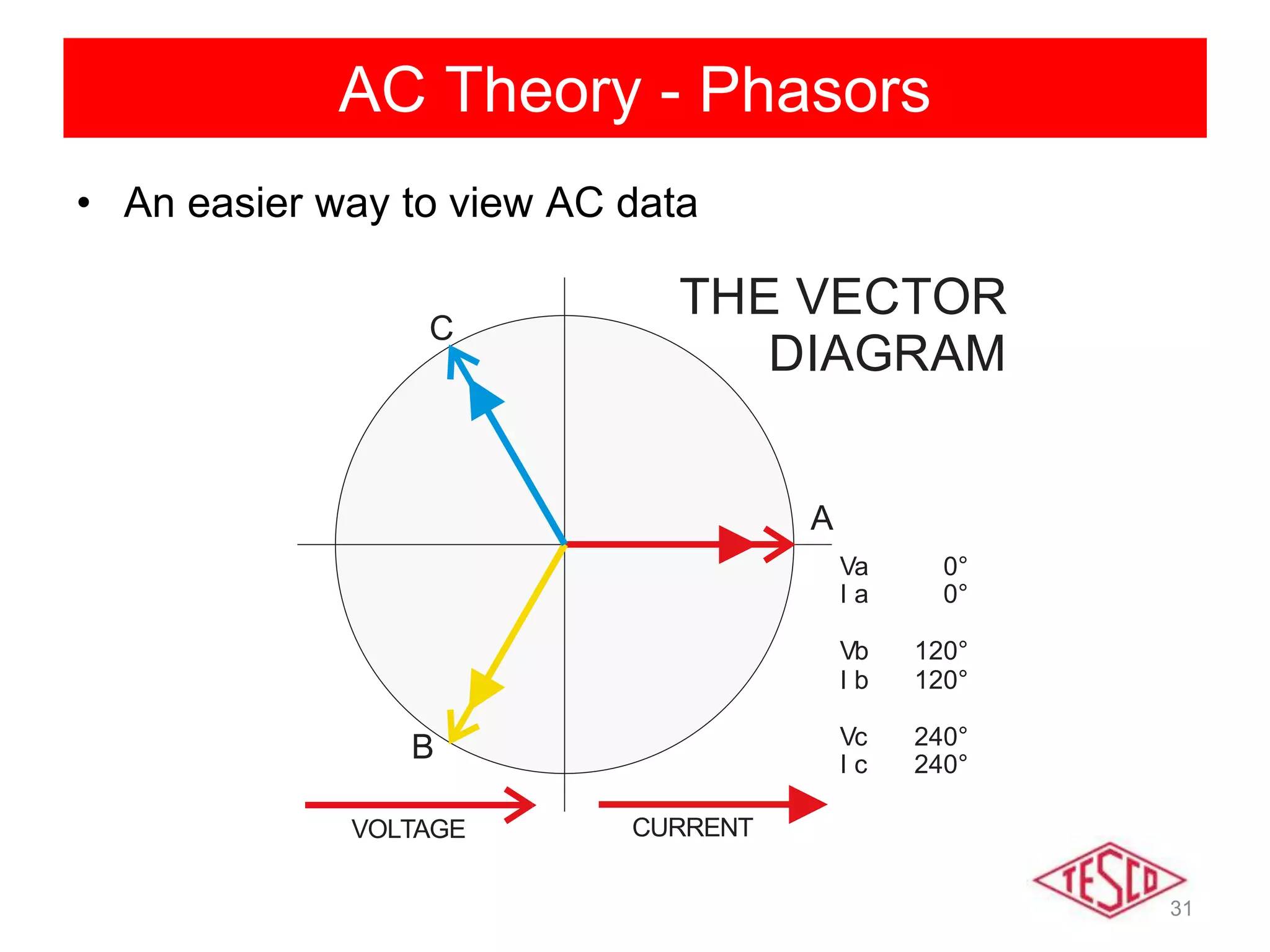
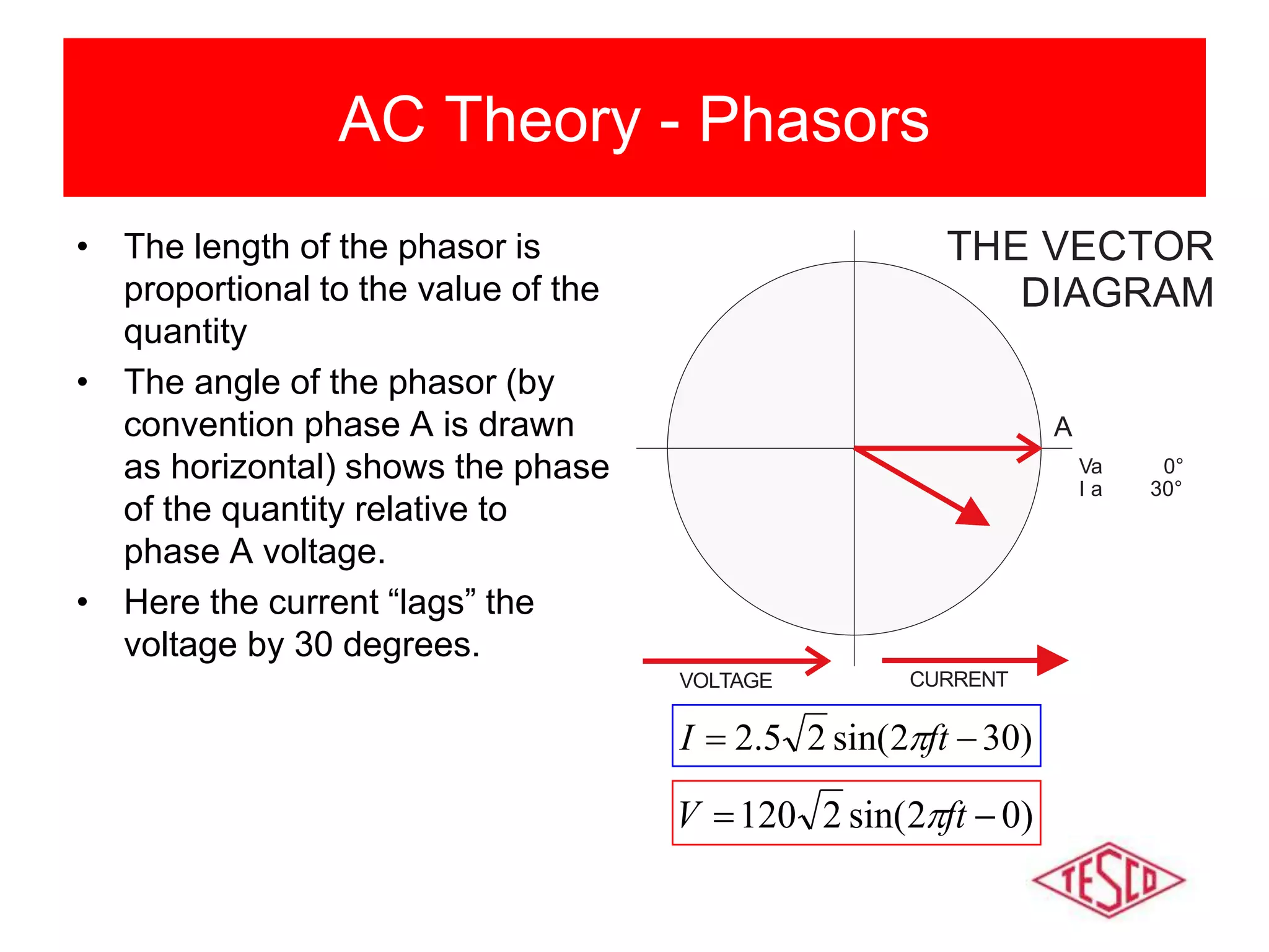
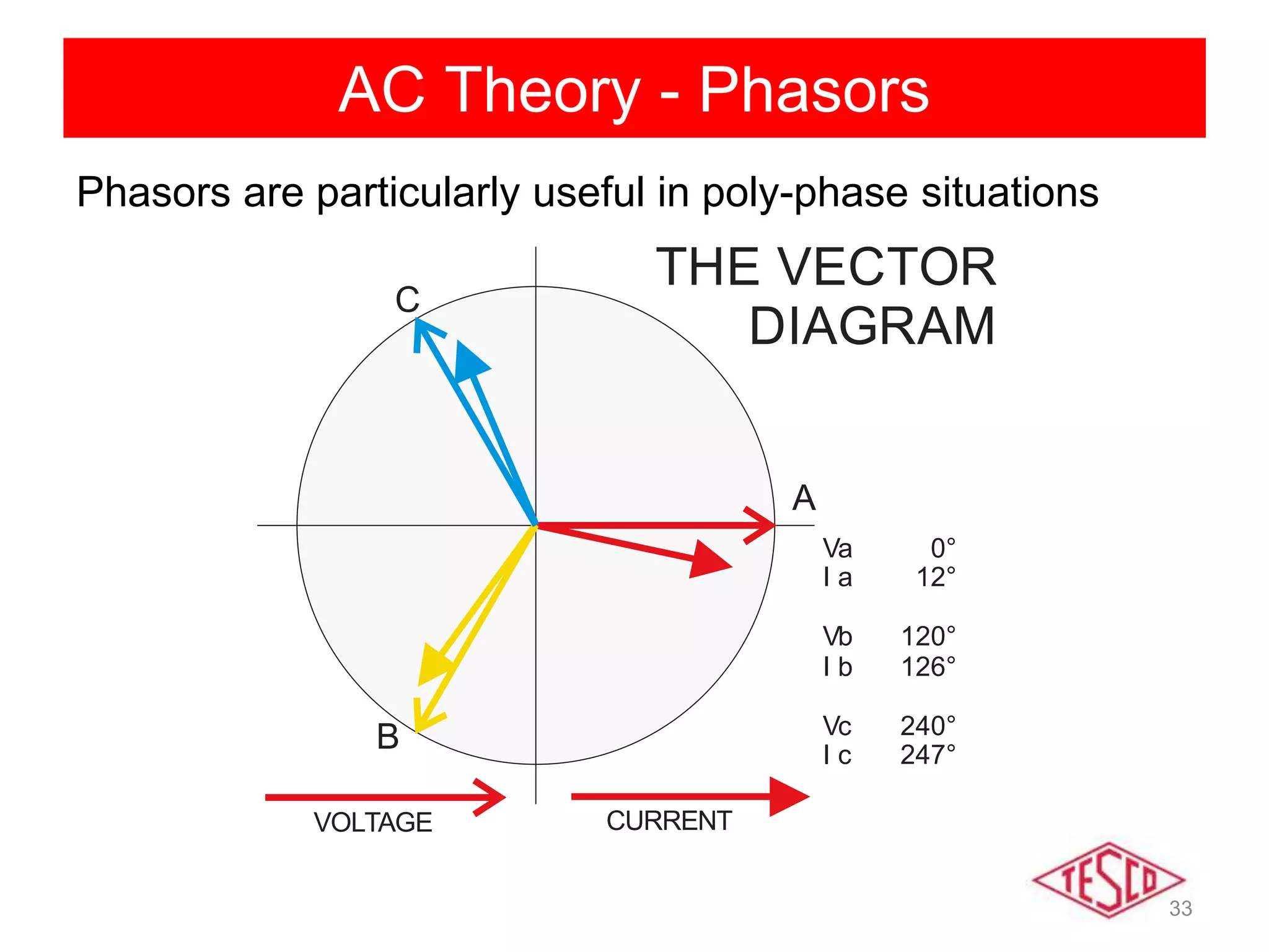
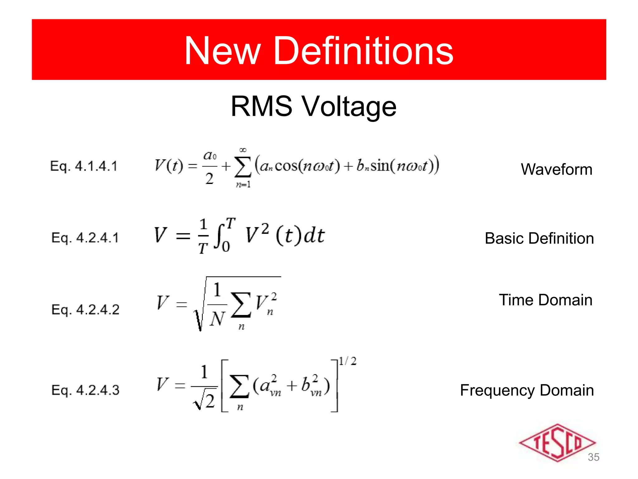
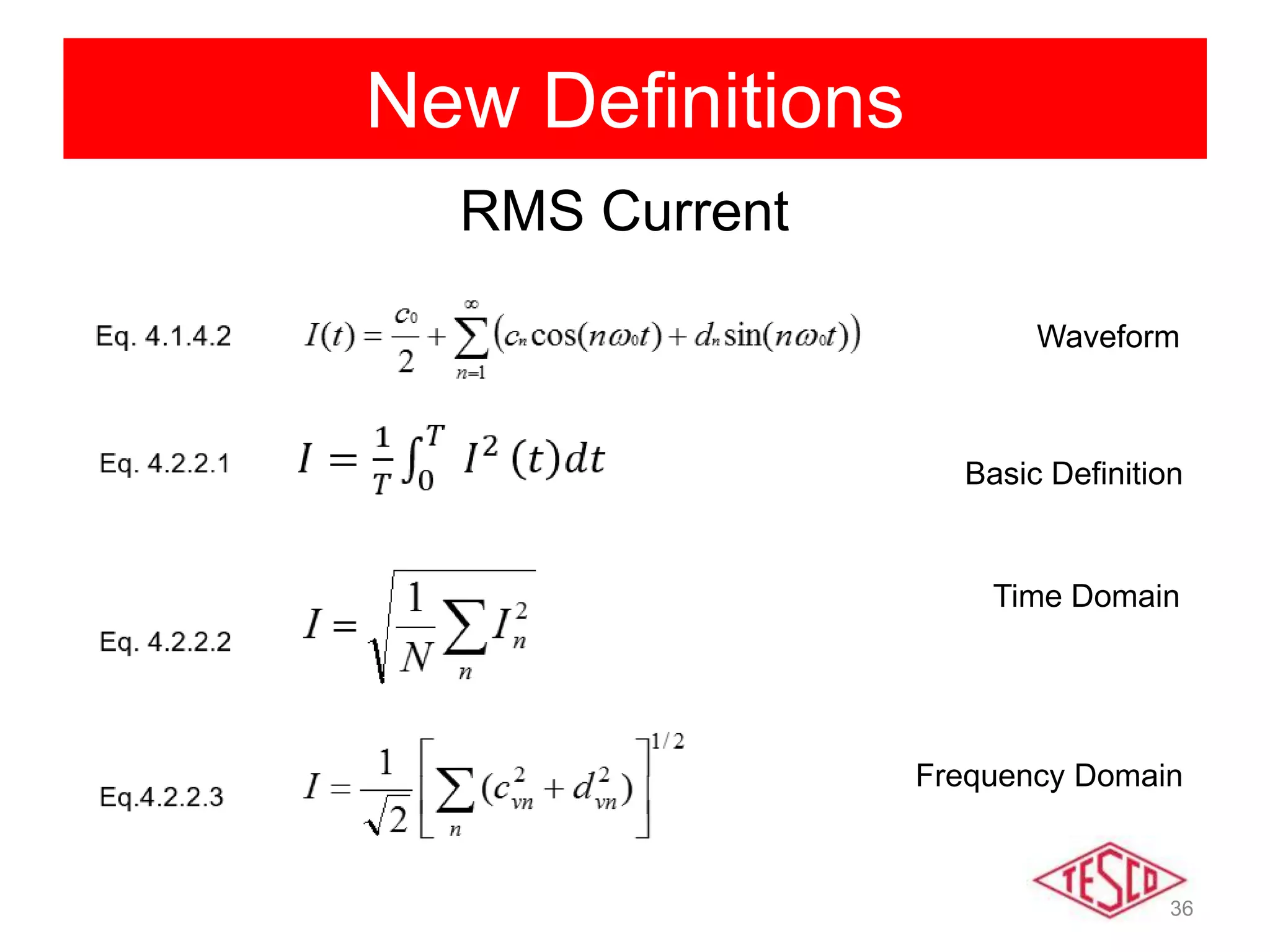
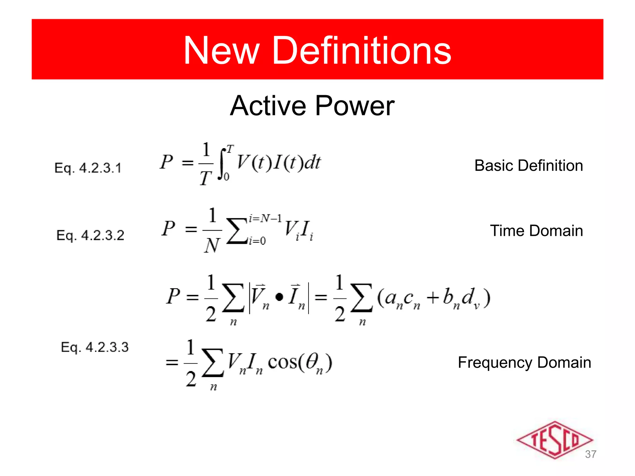
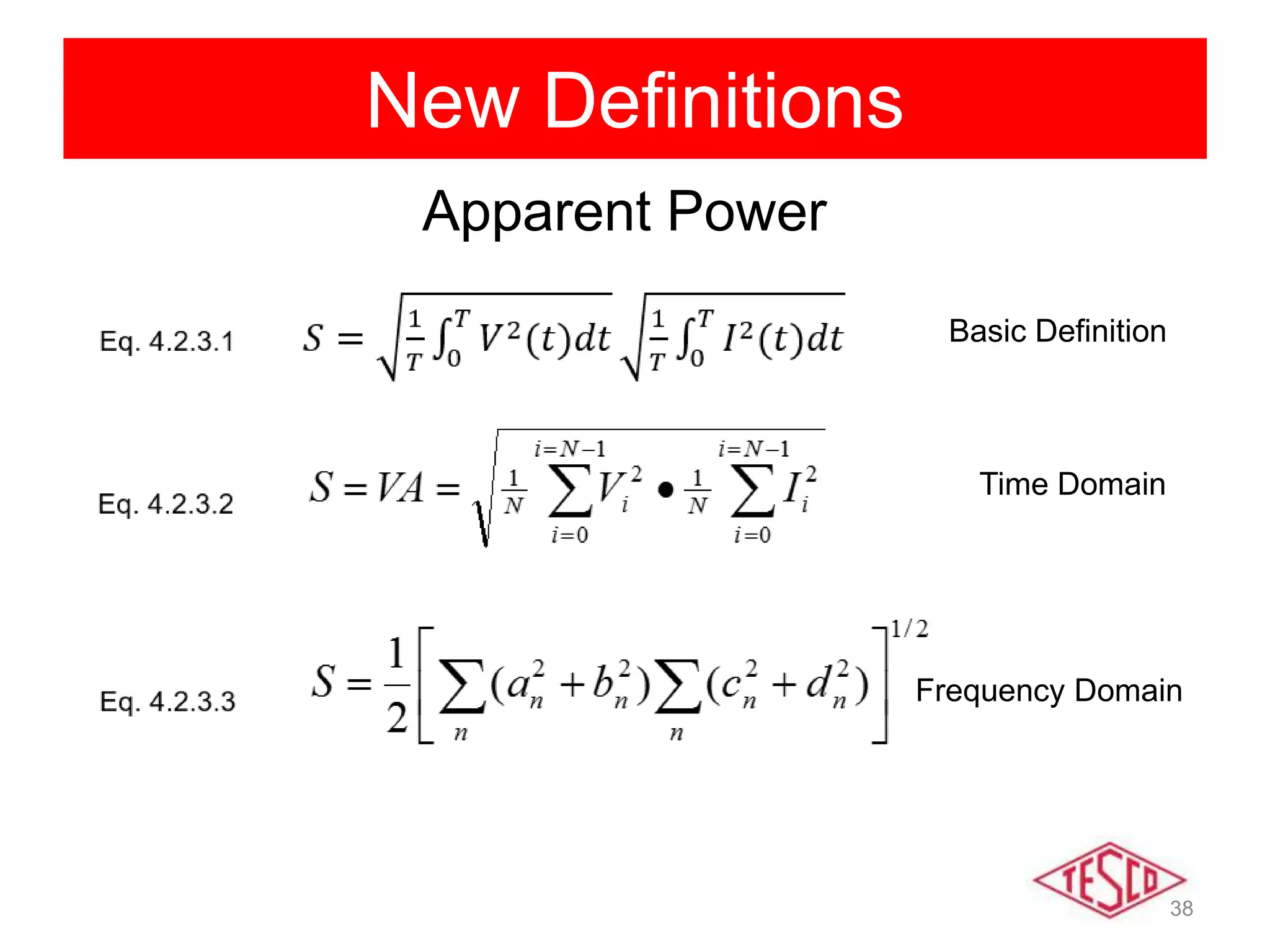
Theory of AC and
DC Meter Testing
Prepared by Bill Hardy, TESCO
For North Carolina Electric Meter School
Single Phase
Tuesday, June 25, 2019 at 3:15 p.m.
2
A Little History
• 1800 Volta
– First electric battery
• 1830-31 Faraday and Henry
– Changing magnetic field can induce an electric
current. Build first very crude electric motors in lab.
• 1832 Pixii
– First crude generation of an AC current.
• 1856 Siemens
– First really practical electric motor
• 1860s Varley, Siemens and Wheatstone
– Each develop electric dynamos (DC Generators).
3
A Little History
• 1870s
– First electric railroad and street lights in Berlin (DC).
• 1880
– First electric elevator (DC).
• 1885-88 Thomson, Ferraris, Tesla
– Each develop AC electric induction motors.
– Tesla is granted a US patent for induction motor in
1888.
• 1890 Dolivo-Dobrovolsky
– First three phase generator, motor and transformer
4
A Little History
• Edison and Westinghouse
– Edison favored DC power distribution, Westinghouse
championed AC distribution.
– The first US commercial electric systems were
Edison’s DC systems.
• First AC system was in 1893 in Redlands, CA.
Developed by Almirian Decker it used 10,000
volt, three phase primary distribution.
• Siemens, Gauland and Steinmetz were other
pioneers.
5
War of the Currents
Thomas Edison George Westinghouse Nikola Tesla
6
AC Theory - History
• By 1900 AC power systems had won the
battle for power distribution.
– Transformers allowed more efficient
distribution of power over large areas.
– AC motors were cheaper and easier to build.
– AC electric generators were easier to build.
7
AC vs DC
• Direct Current (DC) – an electric current
that flows in one direction.(IEEE100)
• Alternating Current (AC) – an electric
current that reverses direction at regularly
recurring intervals of time. (IEEE100)
8
AC Circuits
• An AC circuit has three general characteristics
– Value
– Frequency
– Phase
• In the US, the household value is 120 Volts with
other common voltages being 208, 240, 277 and
480 Volts. The frequency is 60 Hertz (cycles per
second).
9
AC Theory – Sine Wave
)2sin(   ftVV pk
0
)2sin(2   ftVV rms
120rmsV
169pkV
AC Theory - Phase
Sine Wave
(15.000)
(10.000)
(5.000)
0.000
5.000
10.000
15.000
0 60 120 180 240 300 360 420 480 540 600 660 720
Degrees
Amplitude
)2sin(10 ftV  )302sin(10  ftI 
Here current LAGS voltage.
11
AC vs DC
• In DC theory we learned
– Ohm’s Law
• Voltage = Current x Resistance
• V = IR
– Power
• P = I2R = V2/R
• For AC we would like the same equations to apply.
– Specifically we want to be able to say that a DC
voltage of 10 Volts applied to a resistor of value R
produces the same power dissipation as an AC
voltage of 10 volts applied to the same resistor.
12
AC Theory – RMS
• For DC voltage to equal AC voltage we need
  dtftV
RR
Vdc
)2(sin
1 22
0
2

R
V
R
Vdc
2
2
0
2

DCVV 20 
AC Theory - RMS
)sin(68.169)sin(2120 ttV  
(200)
(150)
(100)
(50)
0
50
100
150
200
0 60 120 180 240 300 360 420 480 540 600 660 720
Amplitude
Degrees
Sine Wave
RMS Value
14
AC Theory – RMS
• So if we want to have the V in our equation for
an AC signal represent the same value as the its
DC counterpart we have
• By convention in AC theory we refer to VDC as
the RMS (Root Mean Squared) voltage.
• When we talk about AC values we always mean
the RMS value not the peak value unless we say
so specifically
)2sin(2)(   ftVtV DC
15
AC vs DC
ACDC
RR VrmsVdc
Idc Irms
V = IR
P = VI = I2R = V2/R
AC Theory – Resistive Load
Sine Wave
-200
-150
-100
-50
0
50
100
150
200
0 60 120 180 240 300 360 420 480 540 600 660 720
Degrees
Amplitude
AC
RVrms
Irms
Resistors are measured in Ohms. When an AC voltage is applied to a resistor, the
current is in degrees. A resistive load is considered a “linear” load because when
the voltage is sinusoidal the current is sinusoidal.
17
AC Theory – Inductive Load
Sine Wave
-200
-150
-100
-50
0
50
100
150
200
0 60 120 180 240 300 360 420 480 540 600 660 720
Degrees
Amplitude
AC
LVrms
Irms
Inductors are measured in Henrys. When an AC voltage is applied to an inductor,
the current is 90 degrees out of phase. We say the current “lags” the voltage. A
inductive load is considered a “linear” load because when the voltage is sinusoidal
the current is sinusoidal.
18
AC Theory – Capacitive Load
Sine Wave
-200
-150
-100
-50
0
50
100
150
200
0 60 120 180 240 300 360 420 480 540 600 660 720
Degrees
Amplitude
AC CVrms
Irms
Capacitors are measured in Farads. When an AC voltage is applied to a capacitor,
the current is 90 degrees out of phase. We say the current “leads” the voltage. A
capacitive load is considered a “linear” load because when the voltage is
sinusoidal the current is sinusoidal.
19
AC Theory – Active Power
• Active Power is defined as P = VI
• Power is a rate, i.e. Energy per unit time.
• The Watt is the unit for Power
– 1 Watt = 1000 Joules/sec
• Since the voltage and current at every point in
time for an AC signal is different, we have to
distinguish between instantaneous power and
average power.
• Generally when we say “power” we mean
average power.
20
AC Theory – Energy
• Energy is power integrated over a period of time.
• The units of Energy are:
– Watt-Hour (abbreviated Wh)
– Kilowatt-Hour (abbreviated kWh)
• A Wh is the total energy consumed when a load
draws one Watt for one hour.
21
AC Theory – Instantaneous Power
Sine Wave
(200)
(150)
(100)
(50)
0
50
100
150
200
0 60 120 180 240 300 360 420 480 540 600 660 720
Degrees
Amplitude
(25000)
(20000)
(15000)
(10000)
(5000)
0
5000
10000
15000
20000
25000
WATTS
)2sin(2120 ftV  )2sin(296 ftI  )2(sin23040 2
ftP 
For a resistive load: ))2cos(1()(sin2 2
tVItVIvip  
P = 11520 Watts
22
AC Theory – Instantaneous Power
Sine Wave
-200
-150
-100
-50
0
50
100
150
200
0 60 120 180 240 300 360 420 480 540 600 660 720
Degrees
Amplitude
-15000
-10000
-5000
0
5000
10000
15000
)2sin(2120 ftV  )902sin(296  ftI  )2sin(11520 ftP 
For an inductive load:
P = 0 Watts
)2sin()90sin()sin(2 tVIttVIvip  
23
AC Theory – Instantaneous Power
Sine Wave
-200
-150
-100
-50
0
50
100
150
200
0 60 120 180 240 300 360 420 480 540 600 660 720
Degrees
Amplitude
-15000
-10000
-5000
0
5000
10000
15000
)2sin(2120 ftV  )902sin(296  ftI  )2sin(11520 ftP 
For an capacitive load:
P = 0 Watts
)2()90()(2 tVISintSintVISinvip  
24
AC Theory – Complex Circuits
• Impedance – The equivalent to the concept of resistance
for an AC circuit. It is also measured in Ohms.
Designated by the symbol X.
• In AC circuits non-resistive impedance affects both the
amplitude and phase of the current.
• A resistor R has an impedance which is frequency
independent. There is no phase shift.
• An inductor has an impedance which is proportional the
frequency, XL = 2πfL. The phase is shifted by 90
degrees lagging.
• A capacitor has an impedance which is inversely
proportional the frequency, XC = 1/2πfC. The phase is
shifted by 90 degrees leading.
25
AC Theory – Complex Circuits
AC
C
Vrms
Irms
R
L
22
)
1
(
C
LR
V
I

 

Amplitude (Current)












R
C
L )
1
(
arctan 


Phase (Current)
VC
V
VL
VC
VR
26
AC Theory – Instantaneous Power
Sine Wave
(200)
(150)
(100)
(50)
0
50
100
150
200
0 60 120 180 240 300 360 420 480 540 600 660 720
Degrees
Amplitude
(25000)
(20000)
(15000)
(10000)
(5000)
0
5000
10000
15000
20000
25000
WATTS
)2sin(2120 ftV  )602sin(296  ftI 
)604cos(2304019953))604cos()60(cos(23040  ftftVIP 
Time Out for Trig
(Right Triangles)
c
a
)cos(
a
b
)tan(
a
c
b
90°
The Right Triangle:
The Pythagorean theory
c2 = a2 + b2
c
b
)sin(
28
AC Theory – Power Triangle
(Sinusoidal Waveforms)
If V = sin(ωt) and I = sin(ωt - θ) (and the load is linear)
then
Active Power = VIcos(θ) Watts
Reactive Power = VIsin(θ) VARs
Apparent Power = VI VA
Power Factor = Active/Apparent = cos(θ)
Watts
VARs
29
Harmonics
Curse of the Modern World
• Every thing discussed so far was based on
“Linear” loads.
– For linear loads the current is always a simple
sine wave. Everything we have discussed is
true.
• For nearly a century after AC power was in
use ALL loads were linear.
• Today, many loads are NON-LINEAR.
30
Harmonic Load Waveforms
ANSI C12.20 now addresses harmonic waveforms as well
as sinusoidal.
-400
-300
-200
-100
0
100
200
300
400
-150
-100
-50
0
50
100
150
0 90 180 270 360
-200
-150
-100
-50
0
50
100
150
200
-150
-100
-50
0
50
100
150
0 90 180 270 360
-8
-6
-4
-2
0
2
4
6
8
-200
-150
-100
-50
0
50
100
150
200
0 90 180 270 360
-150
-100
-50
0
50
100
150
0 60 120 180 240 300 360
Test waveforms being proposed for ANSI C12.20.
-250
-200
-150
-100
-50
0
50
100
150
200
250
-150
-100
-50
0
50
100
150
0.00 100.00 200.00 300.00
-150
-100
-50
0
50
100
150
-150
-100
-50
0
50
100
150
0.00 100.00 200.00 300.00
Current
Voltage
31
AC Theory - Phasors
• An easier way to view AC data
CURRENTVOLTAGE
A
B
C
Va 0°
I a 0°
Vb 120°
I b 120°
Vc 240°
I c 240°
THE VECTOR
DIAGRAM
AC Theory - Phasors
• The length of the phasor is
proportional to the value of the
quantity
• The angle of the phasor (by
convention phase A is drawn
as horizontal) shows the phase
of the quantity relative to
phase A voltage.
• Here the current “lags” the
voltage by 30 degrees.
)302sin(25.2  ftI 
)02sin(2120  ftV 
CURRENTVOLTAGE
A
Va 0°
I a 30°
THE VECTOR
DIAGRAM
33
AC Theory - Phasors
Phasors are particularly useful in poly-phase situations
CURRENTVOLTAGE
A
B
C
Va 0°
I a 12°
Vb 120°
I b 126°
Vc 240°
I c 247°
THE VECTOR
DIAGRAM
34
New Energy Definitions
• At the moment there is no non-sinusoidal
definition for VA
• New ANSI Standard coming very soon
C12.31
35
New Definitions
RMS Voltage
Basic Definition
Time Domain
Frequency Domain
Waveform
36
New Definitions
RMS Current
Basic Definition
Time Domain
Frequency Domain
Waveform
37
New Definitions
Active Power
Basic Definition
Time Domain
Frequency Domain
38
New Definitions
Apparent Power
Basic Definition
Time Domain
Frequency Domain
39
Questions and Discussion
Bill Hardy, CTO
TESCO – The Eastern Specialty Company
Bristol, PA
865-279-1090 (cell)
215-785-2338 (office)
This presentation can also be found on the TESCO
website: www.tescometering.com

Theory of AC and DC Meter Testing (Single Phase)

  • 1.
    Theory of ACand DC Meter Testing Prepared by Bill Hardy, TESCO For North Carolina Electric Meter School Single Phase Tuesday, June 25, 2019 at 3:15 p.m.
  • 2.
    2 A Little History •1800 Volta – First electric battery • 1830-31 Faraday and Henry – Changing magnetic field can induce an electric current. Build first very crude electric motors in lab. • 1832 Pixii – First crude generation of an AC current. • 1856 Siemens – First really practical electric motor • 1860s Varley, Siemens and Wheatstone – Each develop electric dynamos (DC Generators).
  • 3.
    3 A Little History •1870s – First electric railroad and street lights in Berlin (DC). • 1880 – First electric elevator (DC). • 1885-88 Thomson, Ferraris, Tesla – Each develop AC electric induction motors. – Tesla is granted a US patent for induction motor in 1888. • 1890 Dolivo-Dobrovolsky – First three phase generator, motor and transformer
  • 4.
    4 A Little History •Edison and Westinghouse – Edison favored DC power distribution, Westinghouse championed AC distribution. – The first US commercial electric systems were Edison’s DC systems. • First AC system was in 1893 in Redlands, CA. Developed by Almirian Decker it used 10,000 volt, three phase primary distribution. • Siemens, Gauland and Steinmetz were other pioneers.
  • 5.
    5 War of theCurrents Thomas Edison George Westinghouse Nikola Tesla
  • 6.
    6 AC Theory -History • By 1900 AC power systems had won the battle for power distribution. – Transformers allowed more efficient distribution of power over large areas. – AC motors were cheaper and easier to build. – AC electric generators were easier to build.
  • 7.
    7 AC vs DC •Direct Current (DC) – an electric current that flows in one direction.(IEEE100) • Alternating Current (AC) – an electric current that reverses direction at regularly recurring intervals of time. (IEEE100)
  • 8.
    8 AC Circuits • AnAC circuit has three general characteristics – Value – Frequency – Phase • In the US, the household value is 120 Volts with other common voltages being 208, 240, 277 and 480 Volts. The frequency is 60 Hertz (cycles per second).
  • 9.
    9 AC Theory –Sine Wave )2sin(   ftVV pk 0 )2sin(2   ftVV rms 120rmsV 169pkV
  • 10.
    AC Theory -Phase Sine Wave (15.000) (10.000) (5.000) 0.000 5.000 10.000 15.000 0 60 120 180 240 300 360 420 480 540 600 660 720 Degrees Amplitude )2sin(10 ftV  )302sin(10  ftI  Here current LAGS voltage.
  • 11.
    11 AC vs DC •In DC theory we learned – Ohm’s Law • Voltage = Current x Resistance • V = IR – Power • P = I2R = V2/R • For AC we would like the same equations to apply. – Specifically we want to be able to say that a DC voltage of 10 Volts applied to a resistor of value R produces the same power dissipation as an AC voltage of 10 volts applied to the same resistor.
  • 12.
    12 AC Theory –RMS • For DC voltage to equal AC voltage we need   dtftV RR Vdc )2(sin 1 22 0 2  R V R Vdc 2 2 0 2  DCVV 20 
  • 13.
    AC Theory -RMS )sin(68.169)sin(2120 ttV   (200) (150) (100) (50) 0 50 100 150 200 0 60 120 180 240 300 360 420 480 540 600 660 720 Amplitude Degrees Sine Wave RMS Value
  • 14.
    14 AC Theory –RMS • So if we want to have the V in our equation for an AC signal represent the same value as the its DC counterpart we have • By convention in AC theory we refer to VDC as the RMS (Root Mean Squared) voltage. • When we talk about AC values we always mean the RMS value not the peak value unless we say so specifically )2sin(2)(   ftVtV DC
  • 15.
    15 AC vs DC ACDC RRVrmsVdc Idc Irms V = IR P = VI = I2R = V2/R
  • 16.
    AC Theory –Resistive Load Sine Wave -200 -150 -100 -50 0 50 100 150 200 0 60 120 180 240 300 360 420 480 540 600 660 720 Degrees Amplitude AC RVrms Irms Resistors are measured in Ohms. When an AC voltage is applied to a resistor, the current is in degrees. A resistive load is considered a “linear” load because when the voltage is sinusoidal the current is sinusoidal.
  • 17.
    17 AC Theory –Inductive Load Sine Wave -200 -150 -100 -50 0 50 100 150 200 0 60 120 180 240 300 360 420 480 540 600 660 720 Degrees Amplitude AC LVrms Irms Inductors are measured in Henrys. When an AC voltage is applied to an inductor, the current is 90 degrees out of phase. We say the current “lags” the voltage. A inductive load is considered a “linear” load because when the voltage is sinusoidal the current is sinusoidal.
  • 18.
    18 AC Theory –Capacitive Load Sine Wave -200 -150 -100 -50 0 50 100 150 200 0 60 120 180 240 300 360 420 480 540 600 660 720 Degrees Amplitude AC CVrms Irms Capacitors are measured in Farads. When an AC voltage is applied to a capacitor, the current is 90 degrees out of phase. We say the current “leads” the voltage. A capacitive load is considered a “linear” load because when the voltage is sinusoidal the current is sinusoidal.
  • 19.
    19 AC Theory –Active Power • Active Power is defined as P = VI • Power is a rate, i.e. Energy per unit time. • The Watt is the unit for Power – 1 Watt = 1000 Joules/sec • Since the voltage and current at every point in time for an AC signal is different, we have to distinguish between instantaneous power and average power. • Generally when we say “power” we mean average power.
  • 20.
    20 AC Theory –Energy • Energy is power integrated over a period of time. • The units of Energy are: – Watt-Hour (abbreviated Wh) – Kilowatt-Hour (abbreviated kWh) • A Wh is the total energy consumed when a load draws one Watt for one hour.
  • 21.
    21 AC Theory –Instantaneous Power Sine Wave (200) (150) (100) (50) 0 50 100 150 200 0 60 120 180 240 300 360 420 480 540 600 660 720 Degrees Amplitude (25000) (20000) (15000) (10000) (5000) 0 5000 10000 15000 20000 25000 WATTS )2sin(2120 ftV  )2sin(296 ftI  )2(sin23040 2 ftP  For a resistive load: ))2cos(1()(sin2 2 tVItVIvip   P = 11520 Watts
  • 22.
    22 AC Theory –Instantaneous Power Sine Wave -200 -150 -100 -50 0 50 100 150 200 0 60 120 180 240 300 360 420 480 540 600 660 720 Degrees Amplitude -15000 -10000 -5000 0 5000 10000 15000 )2sin(2120 ftV  )902sin(296  ftI  )2sin(11520 ftP  For an inductive load: P = 0 Watts )2sin()90sin()sin(2 tVIttVIvip  
  • 23.
    23 AC Theory –Instantaneous Power Sine Wave -200 -150 -100 -50 0 50 100 150 200 0 60 120 180 240 300 360 420 480 540 600 660 720 Degrees Amplitude -15000 -10000 -5000 0 5000 10000 15000 )2sin(2120 ftV  )902sin(296  ftI  )2sin(11520 ftP  For an capacitive load: P = 0 Watts )2()90()(2 tVISintSintVISinvip  
  • 24.
    24 AC Theory –Complex Circuits • Impedance – The equivalent to the concept of resistance for an AC circuit. It is also measured in Ohms. Designated by the symbol X. • In AC circuits non-resistive impedance affects both the amplitude and phase of the current. • A resistor R has an impedance which is frequency independent. There is no phase shift. • An inductor has an impedance which is proportional the frequency, XL = 2πfL. The phase is shifted by 90 degrees lagging. • A capacitor has an impedance which is inversely proportional the frequency, XC = 1/2πfC. The phase is shifted by 90 degrees leading.
  • 25.
    25 AC Theory –Complex Circuits AC C Vrms Irms R L 22 ) 1 ( C LR V I     Amplitude (Current)             R C L ) 1 ( arctan    Phase (Current) VC V VL VC VR
  • 26.
    26 AC Theory –Instantaneous Power Sine Wave (200) (150) (100) (50) 0 50 100 150 200 0 60 120 180 240 300 360 420 480 540 600 660 720 Degrees Amplitude (25000) (20000) (15000) (10000) (5000) 0 5000 10000 15000 20000 25000 WATTS )2sin(2120 ftV  )602sin(296  ftI  )604cos(2304019953))604cos()60(cos(23040  ftftVIP 
  • 27.
    Time Out forTrig (Right Triangles) c a )cos( a b )tan( a c b 90° The Right Triangle: The Pythagorean theory c2 = a2 + b2 c b )sin(
  • 28.
    28 AC Theory –Power Triangle (Sinusoidal Waveforms) If V = sin(ωt) and I = sin(ωt - θ) (and the load is linear) then Active Power = VIcos(θ) Watts Reactive Power = VIsin(θ) VARs Apparent Power = VI VA Power Factor = Active/Apparent = cos(θ) Watts VARs
  • 29.
    29 Harmonics Curse of theModern World • Every thing discussed so far was based on “Linear” loads. – For linear loads the current is always a simple sine wave. Everything we have discussed is true. • For nearly a century after AC power was in use ALL loads were linear. • Today, many loads are NON-LINEAR.
  • 30.
    30 Harmonic Load Waveforms ANSIC12.20 now addresses harmonic waveforms as well as sinusoidal. -400 -300 -200 -100 0 100 200 300 400 -150 -100 -50 0 50 100 150 0 90 180 270 360 -200 -150 -100 -50 0 50 100 150 200 -150 -100 -50 0 50 100 150 0 90 180 270 360 -8 -6 -4 -2 0 2 4 6 8 -200 -150 -100 -50 0 50 100 150 200 0 90 180 270 360 -150 -100 -50 0 50 100 150 0 60 120 180 240 300 360 Test waveforms being proposed for ANSI C12.20. -250 -200 -150 -100 -50 0 50 100 150 200 250 -150 -100 -50 0 50 100 150 0.00 100.00 200.00 300.00 -150 -100 -50 0 50 100 150 -150 -100 -50 0 50 100 150 0.00 100.00 200.00 300.00 Current Voltage
  • 31.
    31 AC Theory -Phasors • An easier way to view AC data CURRENTVOLTAGE A B C Va 0° I a 0° Vb 120° I b 120° Vc 240° I c 240° THE VECTOR DIAGRAM
  • 32.
    AC Theory -Phasors • The length of the phasor is proportional to the value of the quantity • The angle of the phasor (by convention phase A is drawn as horizontal) shows the phase of the quantity relative to phase A voltage. • Here the current “lags” the voltage by 30 degrees. )302sin(25.2  ftI  )02sin(2120  ftV  CURRENTVOLTAGE A Va 0° I a 30° THE VECTOR DIAGRAM
  • 33.
    33 AC Theory -Phasors Phasors are particularly useful in poly-phase situations CURRENTVOLTAGE A B C Va 0° I a 12° Vb 120° I b 126° Vc 240° I c 247° THE VECTOR DIAGRAM
  • 34.
    34 New Energy Definitions •At the moment there is no non-sinusoidal definition for VA • New ANSI Standard coming very soon C12.31
  • 35.
    35 New Definitions RMS Voltage BasicDefinition Time Domain Frequency Domain Waveform
  • 36.
    36 New Definitions RMS Current BasicDefinition Time Domain Frequency Domain Waveform
  • 37.
    37 New Definitions Active Power BasicDefinition Time Domain Frequency Domain
  • 38.
    38 New Definitions Apparent Power BasicDefinition Time Domain Frequency Domain
  • 39.
    39 Questions and Discussion BillHardy, CTO TESCO – The Eastern Specialty Company Bristol, PA 865-279-1090 (cell) 215-785-2338 (office) This presentation can also be found on the TESCO website: www.tescometering.com