TSSM’S
BHIVARABAI SAWANT COLLEGEOF ENGINEERING AND
RESEARCH , POLYTECHNIC, NARHE,PUNE-41
Department Of Electrical Engineering
Course : ECI (22324)
Unit 1 : Single phase AC series circuit( 15
Marks)
C324.1 : Troubleshoot problems related to single phase AC
series circuit
2.
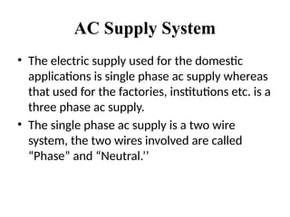
AC Supply System
•The electric supply used for the domestic
applications is single phase ac supply whereas
that used for the factories, institutions etc. is a
three phase ac supply.
• The single phase ac supply is a two wire
system, the two wires involved are called
“Phase” and “Neutral.’’
3.
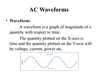
AC Waveforms
• Waveform:
Awaveform is a graph of magnitude of a
quantity with respect to time.
The quantity plotted on the X-axis is
time and the quantity plotted on the Y-axis will
be voltage, current, power etc.
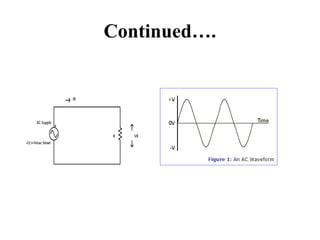
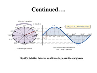
Continued….
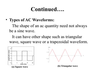
• Types ofAC Waveforms:
The shape of an ac quantity need not always
be a sine wave.
It can have other shape such as triangular
wave, square wave or a trapezoidal waveform.
(a) Square wave (b) Triangular wave
6.
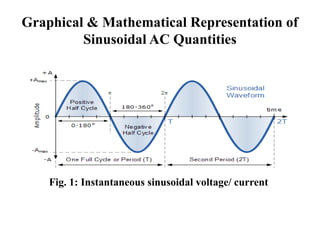
Graphical & MathematicalRepresentation of
Sinusoidal AC Quantities
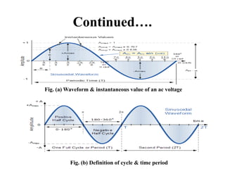
Fig. 1: Instantaneous sinusoidal voltage/ current
7.
Continued….
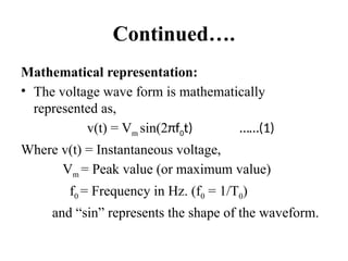
Mathematical representation:
• Thevoltage wave form is mathematically
represented as,
v(t) = Vm sin(2πf0t) ……(1)
Where v(t) = Instantaneous voltage,
Vm = Peak value (or maximum value)
f0 = Frequency in Hz. (f0 = 1/T0)
and “sin” represents the shape of the waveform.
8.
Continued….
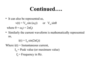
• It canalso be represented as,
v(t) = Vm sin (ω0t) or Vm sinθ
where θ = ω0t = 2πf0t
• Similarly the current waveform is mathematically represented
as,
i(t) = Im sin(2πf0t)
Where i(t) = Instantaneous current,
Im = Peak value (or maximum value)
f0 = Frequency in Hz.
9.
Definitions
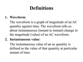
1. Waveform:
The waveformis a graph of magnitude of an AC
quantity against time. The waveform tells us
about instantaneous (instant to instant) change in
the magnitude (value) of an AC waveform.
2. Instantaneous value:
The instantaneous value of an ac quantity is
defined as the value of that quantity at particular
instant of time.
Continued….
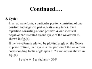
3. Cycle:
In anac waveform, a particular portion consisting of one
positive and negative part repeats many times. Each
repetition consisting of one positive & one identical
negative part is called as one cycle of the waveform as
shown in fig.(b).
If the waveform is plotted by plotting angle on the X-axis
in place of time, then cycle is that portion of the waveform
corresponding to the angle span of 2 π radians as shown in
fig. (a).
1 cycle 2
≅ π radians = 3600
12.
Continued….
4. Time Periodor Periodic Time (T):
Time period (T) is defined as the time taken in seconds by
the waveform of an ac quantity to complete one cycle. After
every T seconds, the cycle repeats itself as shown in fig.(b).
5. Frequency:
Frequency is defined as the number of cycles completed by
an alternating quantity in one second. It is denoted by “f”
and its units are cycles/second or Hertz (Hz).
13.
Continued….
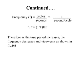
Frequency (f) =cycles
seconds
= 1
Second/cycle
∴ f = (1/T)Hz
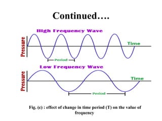
Therefore as the time period increases, the
frequency decreases and vice-versa as shown in
fig.(c)
Continued….
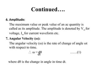
6. Amplitude:
The maximumvalue or peak value of an ac quantity is
called as its amplitude. The amplitude is denoted by Vm for
voltage, Im for current waveform etc.
7. Angular Velocity (ω):
The angular velocity (ω) is the rate of change of angle ωt
with respect to time.
∴ ω = dθ ……(1)
where dθ is the change in angle in time dt.
dt
16.
Continued….
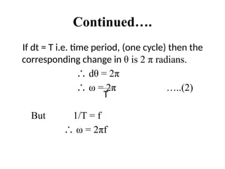
If dt =T i.e. time period, (one cycle) then the
corresponding change in θ is 2 π radians.
∴ dθ = 2π
∴ ω = 2π …..(2)
But 1/T = f
∴ ω = 2πf
T
17.
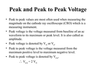
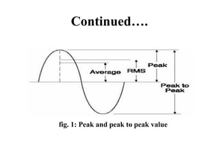
Peak and Peakto Peak Voltage
• Peak to peak values are most often used when measuring the
magnitude on the cathode ray oscilloscope (CRO) which is a
measuring instrument.
• Peak voltage is the voltage measured from baseline of an ac
waveform to its maximum or peak level. It is also called as
amplitude.
• Peak voltage is denoted by Vm or Vp.
• Peak to peak voltage is the voltage measured from the
maximum positive level to maximum negative level.
• Peak to peak voltage is denoted by Vp-p.
∴ Vp-p = 2 Vm
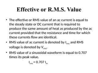
Effective or R.M.S.Value
• The effective or RMS value of an ac current is equal to
the steady state or DC current that is required to
produce the same amount of heat as produced by the ac
current provided that the resistance and time for which
these currents flow are identical.
• RMS value of ac current is denoted by Irms and RMS
voltage is denoted by Vrms.
• RMS value of a sinusoidal waveform is equal to 0.707
times its peak value.
Irms = 0.707 Im
20.
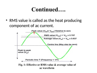
Continued….
• RMS valueis called as the heat producing
component of ac current.
Fig. 1: Effective or RMS value & average value of
ac waveform
21.
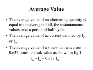
Average Value
• Theaverage value of an alternating quantity is
equal to the average of all, the instantaneous
values over a period of half cycle.
• The average value of ac current denoted by Iav
or Idc.
• The average value of a sinusoidal waveform is
0.637 times its peak value as shown in fig.1.
Iav = Idc = 0.637 Im
22.
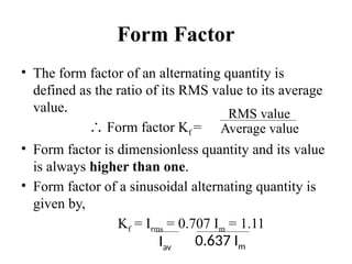
Form Factor
• Theform factor of an alternating quantity is
defined as the ratio of its RMS value to its average
value.
∴ Form factor Kf =
• Form factor is dimensionless quantity and its value
is always higher than one.
• Form factor of a sinusoidal alternating quantity is
given by,
Kf = Irms = 0.707 Im = 1.11
Iav
0.637 Im
RMS value
Average value
23.
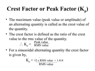
Crest Factor orPeak Factor (Kp)
• The maximum value (peak value or amplitude) of
an alternating quantity is called as the crest value of
the quantity.
• The crest factor is defined as the ratio of the crest
value to the rms value of the quantity.
∴ Kp =
• For a sinusoidal alternating quantity the crest factor
is given by,
Kp = √2 x RMS value = 1.414
RMS value
Peak value
RMS value
24.
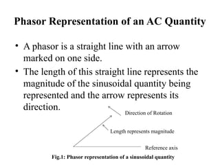
Phasor Representation ofan AC Quantity
• A phasor is a straight line with an arrow
marked on one side.
• The length of this straight line represents the
magnitude of the sinusoidal quantity being
represented and the arrow represents its
direction. Direction of Rotation
Length represents magnitude
Reference axis
Fig.1: Phasor representation of a sinusoidal quantity
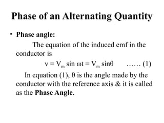
Phase of anAlternating Quantity
• Phase angle:
The equation of the induced emf in the
conductor is
v = Vm sin ωt = Vm sinθ …… (1)
In equation (1), θ is the angle made by the
conductor with the reference axis & it is called
as the Phase Angle.
27.
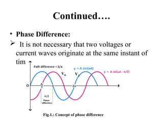
Continued….
• Phase Difference:
It is not necessary that two voltages or
current waves originate at the same instant of
time.
Fig.1.: Concept of phase difference
VA
VB
28.
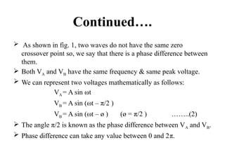
Continued….
As shownin fig. 1, two waves do not have the same zero
crossover point so, we say that there is a phase difference between
them.
Both VA and VB have the same frequency & same peak voltage.
We can represent two voltages mathematically as follows:
VA = A sin ωt
VB = A sin (ωt – π/2 )
VB = A sin (ωt – ø ) (ø = π/2 ) ……..(2)
The angle π/2 is known as the phase difference between VA and VB.
Phase difference can take any value between 0 and 2π.
29.
Continued….
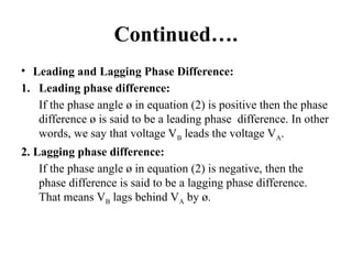
• Leading andLagging Phase Difference:
1. Leading phase difference:
If the phase angle ø in equation (2) is positive then the phase
difference ø is said to be a leading phase difference. In other
words, we say that voltage VB leads the voltage VA.
2. Lagging phase difference:
If the phase angle ø in equation (2) is negative, then the
phase difference is said to be a lagging phase difference.
That means VB lags behind VA by ø.
30.
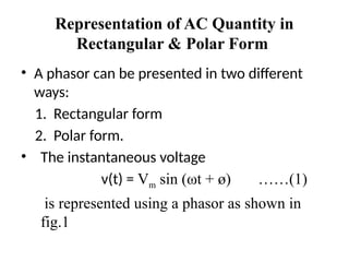
Representation of ACQuantity in
Rectangular & Polar Form
• A phasor can be presented in two different
ways:
1. Rectangular form
2. Polar form.
• The instantaneous voltage
v(t) = Vm sin (ωt + ø) ……(1)
is represented using a phasor as shown in
fig.1
31.
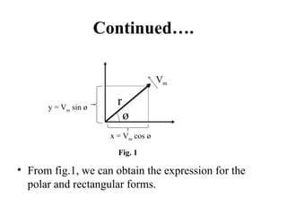
Continued….
• From fig.1,we can obtain the expression for the
polar and rectangular forms.
ø
r
Vm
y = Vm sin ø
x = Vm cos ø
Fig. 1
32.
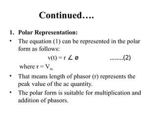
Continued….
1. Polar Representation:
•The equation (1) can be represented in the polar
form as follows:
v(t) = r ∠ ø ……..(2)
where r = Vm.
• That means length of phasor (r) represents the
peak value of the ac quantity.
• The polar form is suitable for multiplication and
addition of phasors.
33.
Continued….
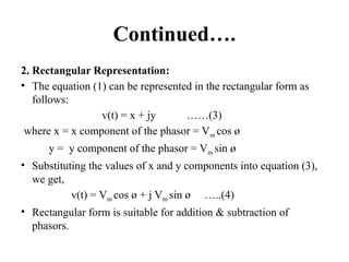
2. Rectangular Representation:
•The equation (1) can be represented in the rectangular form as
follows:
v(t) = x + jy ……(3)
where x = x component of the phasor = Vm cos ø
y = y component of the phasor = Vm sin ø
• Substituting the values of x and y components into equation (3),
we get,
v(t) = Vm cos ø + j Vm sin ø …..(4)
• Rectangular form is suitable for addition & subtraction of
phasors.
34.
Single Phase ACCircuits
• The three basic elements of any ac circuit are
Resistance (R), Inductance (L), and capacitance
(C).
• The three basic circuits are:
1. Purely resistive AC circuit.
2. Purely inductive AC circuit.
3. Purely capacitive AC circuit.
35.
Continued….
• Reactance:
Reactance canbe of two types:
1. Inductive reactance XL.
2. Capacitive reactance XC.
1. Inductive reactance (XL):
• We define the inductive reactance XL as,
XL = ωL = 2πfL and the unit is ohm (Ω ).
• We can define inductive reactance as the opposition to the
flow of an alternating current, offered by an inductance.
36.
Continued….
2. Capacitive Reactance(XC):
• We define the capacitive reactance XC as,
XC =
1
ωC
= 1
2πfC
…….(1)
•The unit of capacitive reactance is ohm (Ω).
• Thus capacitive reactance XC is defined as the
opposition offered by a pure capacitor to the flow of
alternating current.
• Equation (1) shows that the capacitive reactance is
inversely proportional to the frequency of the applied
voltage if C is constant.
37.
Continued….
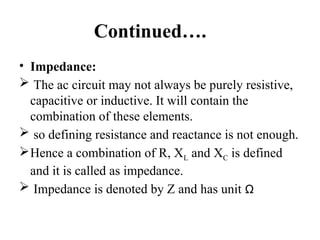
• Impedance:
Theac circuit may not always be purely resistive,
capacitive or inductive. It will contain the
combination of these elements.
so defining resistance and reactance is not enough.
Hence a combination of R, XL and XC is defined
and it is called as impedance.
Impedance is denoted by Z and has unit Ω
38.
Continued….
Impedance can beexpressed in polar form as
follows:
Z = |Z| ø
∠
where |Z| = magnitude of Z,
ø = phase angle.
And it is expressed in rectangular form as,
Z = R + jX
where |Z| = √(R2
+ X2
) and ø = tan-1
[X/R]
39.
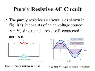
Purely Resistive ACCircuit
• The purely resistive ac circuit is as shown in
fig. 1(a). It consists of an ac voltage source
v = Vm sin ωt, and a resistor R connected
across it.
Fig. 1(a): Purely resistive ac circuit Fig. 1(b): Voltage and current waveform
40.
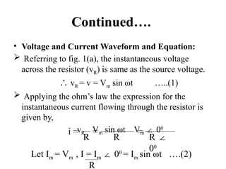
Continued….
• Voltage andCurrent Waveform and Equation:
Referring to fig. 1(a), the instantaneous voltage
across the resistor (vR) is same as the source voltage.
∴ vR = v = Vm sin ωt …..(1)
Applying the ohm’s law the expression for the
instantaneous current flowing through the resistor is
given by,
vR Vm sin ωt Vm 0
∠ 0
R R R ∠
00
i = = =
Let Im = Vm , I = Im 0
∠ 0
= Im sin ωt ….(2)
R
41.
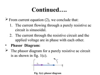
Continued….
From currentequation (2), we conclude that:
1. The current flowing through a purely resistive ac
circuit is sinusoidal.
2. The current through the resistive circuit and the
applied voltage are in phase with each other.
• Phasor Diagram:
The phasor diagram for a purely resistive ac circuit
is as shown in fig. 1(c).
Fig. 1(c): phasor diagram
42.
Continued….
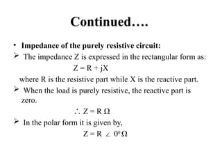
• Impedance ofthe purely resistive circuit:
The impedance Z is expressed in the rectangular form as:
Z = R + jX
where R is the resistive part while X is the reactive part.
When the load is purely resistive, the reactive part is
zero.
∴ Z = R Ω
In the polar form it is given by,
Z = R 0
∠ 0
Ω
43.
Continued….
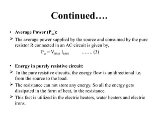
• Average Power(Pav):
The average power supplied by the source and consumed by the pure
resistor R connected in an AC circuit is given by,
Pav = VRMS IRMS ……. (3)
• Energy in purely resistive circuit:
In the pure resistive circuits, the energy flow is unidirectional i.e.
from the source to the load.
The resistance can not store any energy. So all the energy gets
dissipated in the form of heat, in the resistance.
This fact is utilized in the electric heaters, water heaters and electric
irons.
44.
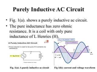
Purely Inductive ACCircuit
• Fig. 1(a). shows a purely inductive ac circuit.
• The pure inductance has zero ohmic
resistance. It is a coil with only pure
inductance of L Henries (H).
Fig. 1(a): A purely inductive ac circuit Fig 1(b): current and voltage waveform
45.
Continued….
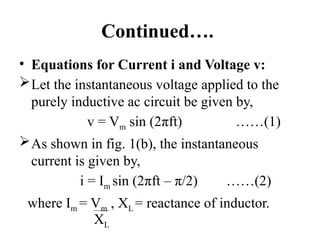
• Equations forCurrent i and Voltage v:
Let the instantaneous voltage applied to the
purely inductive ac circuit be given by,
v = Vm sin (2πft) ……(1)
As shown in fig. 1(b), the instantaneous
current is given by,
i = Im sin (2πft – π/2) ……(2)
where Im = Vm , XL = reactance of inductor.
XL
46.
Continued….
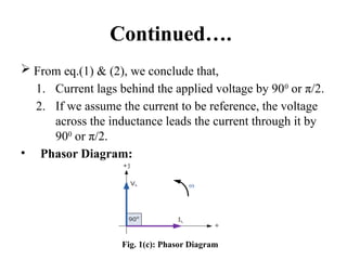
From eq.(1)& (2), we conclude that,
1. Current lags behind the applied voltage by 900
or π/2.
2. If we assume the current to be reference, the voltage
across the inductance leads the current through it by
900
or π/2.
• Phasor Diagram:
Fig. 1(c): Phasor Diagram
47.
Continued….
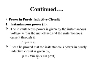
• Power inPurely Inductive Circuit:
1. Instantaneous power (P):
The instantaneous power is given by the instantaneous
voltage across the inductance and the instantaneous
current through it.
∴ p = v x i
It can be proved that the instantaneous power in purely
inductive circuit is given by,
p = - Vm Im x sin (2ωt)
2
48.
Continued….
2. Average power:
The average power supplied to or consumed by a pure inductor
connected in an ac circuit is zero.
∴ Pav = 0
• Impedance of a purely inductive circuit:
When circuit is purely inductive, the resistive part is zero i.e. R =
0.
∴ Z = j XL Ω
In polar form, it is given by,
Z = XL 90
∠ 0
Ω
49.
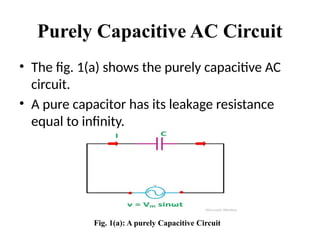
Purely Capacitive ACCircuit
• The fig. 1(a) shows the purely capacitive AC
circuit.
• A pure capacitor has its leakage resistance
equal to infinity.
Fig. 1(a): A purely Capacitive Circuit
50.
Continued….
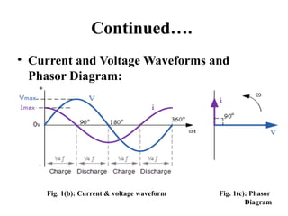
• Current andVoltage Waveforms and
Phasor Diagram:
Fig. 1(b): Current & voltage waveform Fig. 1(c): Phasor
Diagram
51.
Continued….
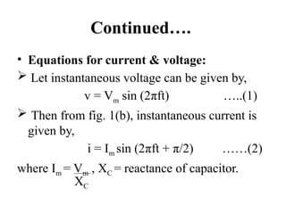
• Equations forcurrent & voltage:
Let instantaneous voltage can be given by,
v = Vm sin (2πft) …..(1)
Then from fig. 1(b), instantaneous current is
given by,
i = Im sin (2πft + π/2) ……(2)
where Im = Vm , XC = reactance of capacitor.
XC
52.
Continued….
From eq.(1) &(2), we conclude that,
1. Current lags behind the applied voltage by
900
or π/2.
2. If we assume the current to be reference,
the voltage across the inductance leads the
current through it by 900
or π/2.
53.
Continued….
• Power inPurely Capacitive Circuit:
1. Instantaneous power (P):
The instantaneous power is given by,
p = v x I
It can be proved that the instantaneous power
in purely capacitive circuit is given by,
p = - Vm Im x sin (2ωt)
2
54.
Continued….
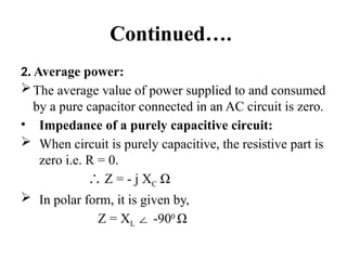
2. Average power:
Theaverage value of power supplied to and consumed
by a pure capacitor connected in an AC circuit is zero.
• Impedance of a purely capacitive circuit:
When circuit is purely capacitive, the resistive part is
zero i.e. R = 0.
∴ Z = - j XC Ω
In polar form, it is given by,
Z = XL -90
∠ 0
Ω
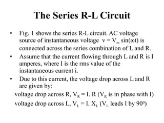
The Series R-LCircuit
• Fig. 1 shows the series R-L circuit. AC voltage
source of instantaneous voltage v = Vm sin(ωt) is
connected across the series combination of L and R.
• Assume that the current flowing through L and R is I
amperes, where I is the rms value of the
instantaneous current i.
• Due to this current, the voltage drop across L and R
are given by:
voltage drop across R, VR = I. R (VR is in phase with I)
voltage drop across L, VL = I. XL (VL leads I by 900
)
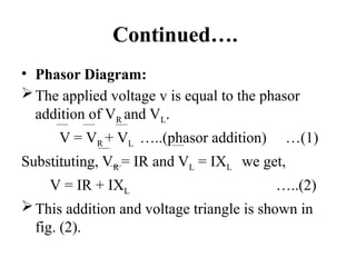
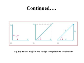
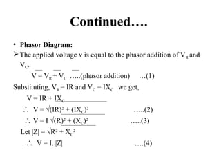
Continued….
• Phasor Diagram:
Theapplied voltage v is equal to the phasor
addition of VR and VL.
V = VR + VL …..(phasor addition) …(1)
Substituting, VR = IR and VL = IXL we get,
V = IR + IXL …..(2)
This addition and voltage triangle is shown in
fig. (2).
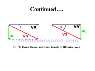
Continued….
• Impedance ofR-L series circuit:
the impedance of R-L series circuit is
expressed in the rectangular form as,
Z = R + jXL .....(3a)
And it is expressed in polar form as,
Z = |Z| ø …...(3b)
∠
where |Z| = √(R2
+ XL
2
) and ø = tan-1
[XL/R]
61.
Continued….
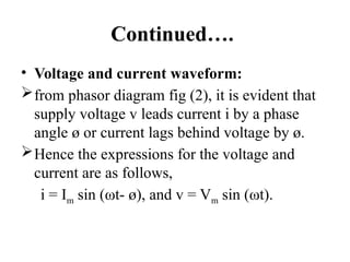
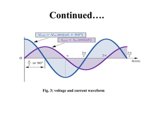
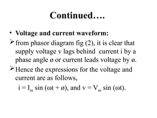
• Voltage andcurrent waveform:
from phasor diagram fig (2), it is evident that
supply voltage v leads current i by a phase
angle ø or current lags behind voltage by ø.
Hence the expressions for the voltage and
current are as follows,
i = Im sin (ωt- ø), and v = Vm sin (ωt).
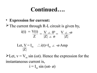
Continued….
• Expression forcurrent:
The current through R-L circuit is given by,
i(t) = V(t)
Z
= V 0
∠ 0
|Z| ø
∠
= V -ø
∠
|Z|
Let, V = Im i(t)=I
∴ m -ø Amp
∠
|Z|
Let, v = Vm sin (ωt). Hence the expression for the
instantaneous current is,
i = Im sin (ωt- ø)
64.
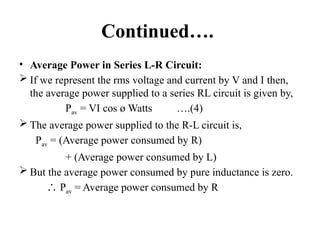
Continued….
• Average Powerin Series L-R Circuit:
If we represent the rms voltage and current by V and I then,
the average power supplied to a series RL circuit is given by,
Pav = VI cos ø Watts ….(4)
The average power supplied to the R-L circuit is,
Pav = (Average power consumed by R)
+ (Average power consumed by L)
But the average power consumed by pure inductance is zero.
∴ Pav = Average power consumed by R
65.
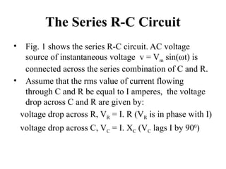
The Series R-CCircuit
• Fig. 1 shows the series R-C circuit. AC voltage
source of instantaneous voltage v = Vm sin(ωt) is
connected across the series combination of C and R.
• Assume that the rms value of current flowing
through C and R be equal to I amperes, the voltage
drop across C and R are given by:
voltage drop across R, VR = I. R (VR is in phase with I)
voltage drop across C, VC = I. XC (VC lags I by 900
)
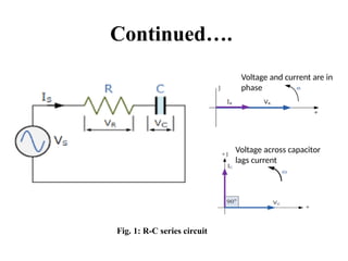
Continued….
• Phasor Diagram:
Theapplied voltage v is equal to the phasor addition of VR and
VC.
V = VR + VC …..(phasor addition) …(1)
Substituting, VR = IR and VC = IXC we get,
V = IR + IXC
∴ V = √(IR)2
+ (IXC)2
…..(2)
∴ V = I √(R)2
+ (XC)2
…..(3)
Let |Z| = √R2
+ XC
2
∴ V = I. |Z| ….(4)
Continued….
• Impedance ofR-C series circuit:
the impedance of R-C series circuit is expressed
in the rectangular form as,
Z = R - jXC
And it is expressed in polar form as,
Z = |Z| -ø
∠
where |Z| = √(R2
+ XC
2
) and ø = tan-1
[-XC/R]
The phase angle is negative for capacitive load.
70.
Continued….
• Voltage andcurrent waveform:
from phasor diagram fig (2), it is clear that
supply voltage v lags behind current i by a
phase angle ø or current leads voltage by ø.
Hence the expressions for the voltage and
current are as follows,
i = Im sin (ωt + ø), and v = Vm sin (ωt).
Continued….
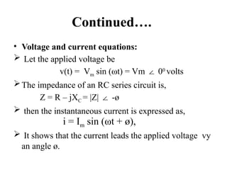
• Voltage andcurrent equations:
Let the applied voltage be
v(t) = Vm sin (ωt) = Vm 0
∠ 0
volts
The impedance of an RC series circuit is,
Z = R – jXC = |Z| -ø
∠
then the instantaneous current is expressed as,
It shows that the current leads the applied voltage vy
an angle ø.
i = Im sin (ωt + ø),
73.
Continued….
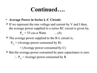
• Average Powerin Series L-C Circuit:
If we represent the rms voltage and current by V and I then,
the average power supplied to a series RC circuit is given by,
Pav = VI cos ø Watts ….(4)
The average power supplied to the R-L circuit is,
Pav = (Average power consumed by R)
+ (Average power consumed by C)
But the average power consumed by pure capacitance is zero.
∴ Pav = Average power consumed by R

![Continued….
Impedance can be expressed in polar form as
follows:
Z = |Z| ø
∠
where |Z| = magnitude of Z,
ø = phase angle.
And it is expressed in rectangular form as,
Z = R + jX
where |Z| = √(R2
+ X2
) and ø = tan-1
[X/R]](https://image.slidesharecdn.com/chapter1-250410032720-4441444a/85/fffffffffffffffffffffffffffffffffffffffffffffffffff1-pptxf-38-320.jpg)
![Continued….
• Impedance of R-L series circuit:
the impedance of R-L series circuit is
expressed in the rectangular form as,
Z = R + jXL .....(3a)
And it is expressed in polar form as,
Z = |Z| ø …...(3b)
∠
where |Z| = √(R2
+ XL
2
) and ø = tan-1
[XL/R]](https://image.slidesharecdn.com/chapter1-250410032720-4441444a/85/fffffffffffffffffffffffffffffffffffffffffffffffffff1-pptxf-60-320.jpg)
![Continued….
• Impedance of R-C series circuit:
the impedance of R-C series circuit is expressed
in the rectangular form as,
Z = R - jXC
And it is expressed in polar form as,
Z = |Z| -ø
∠
where |Z| = √(R2
+ XC
2
) and ø = tan-1
[-XC/R]
The phase angle is negative for capacitive load.](https://image.slidesharecdn.com/chapter1-250410032720-4441444a/85/fffffffffffffffffffffffffffffffffffffffffffffffffff1-pptxf-69-320.jpg)
![AC_CIRCUITS[1].pptx](https://cdn.slidesharecdn.com/ss_thumbnails/accircuits1-230813170350-dc7f310b-thumbnail.jpg?width=640&height=640&fit=bounds)