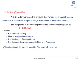
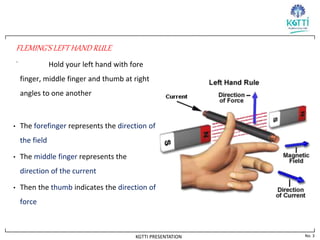
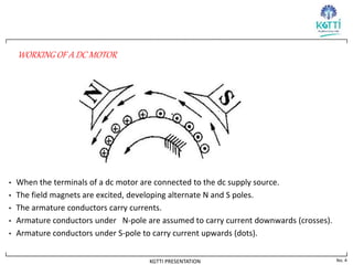
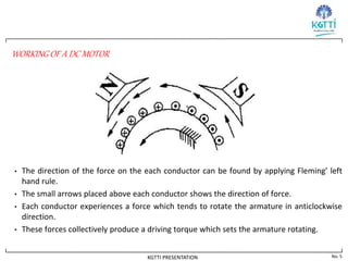
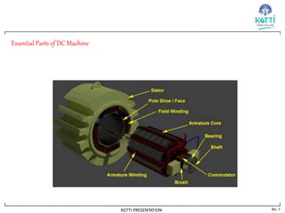
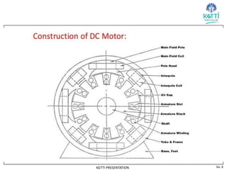
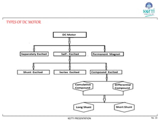
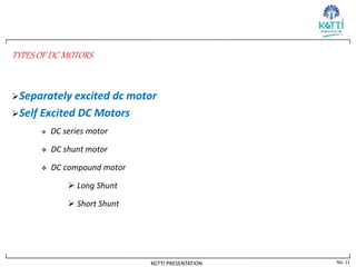
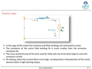
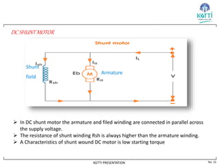
A DC motor converts electrical energy into mechanical energy using the principles that a current carrying conductor placed in a magnetic field experiences a force. It has a stator that houses field windings and a rotor that rotates. There are different types of DC motors including separately excited, series, shunt, and compound motors. Series motors have high starting torque but low speed regulation while shunt motors have low starting torque but good speed regulation, making each suitable for different applications.
2. No. 2
KGTTI PRESENTATION
Principle of operation
A D.C. Motor works on the principle that “whenever a current carrying
conductor is placed in a magnetic field, it experiences a mechanical force”.
The magnitude of the force experienced by the conductor is given by,
F = B.I.L.Sin θ
Where
l B is the Flux Density
l I is the magnitude of current
l L is the length of the conductor
l θ is the angle between Magnetic Field and Conductor
The direction of the force is found by Fleming's left hand rule
3. No. 3
KGTTI PRESENTATION
FLEMING’S LEFT HAND RULE
. Hold your left hand with fore
finger, middle finger and thumb at right
angles to one another
• The forefinger represents the direction of
the field
• The middle finger represents the
direction of the current
• Then the thumb indicates the direction of
force
4. No. 4
KGTTI PRESENTATION
WORKING OF A DC MOTOR
• When the terminals of a dc motor are connected to the dc supply source.
• The field magnets are excited, developing alternate N and S poles.
• The armature conductors carry currents.
• Armature conductors under N-pole are assumed to carry current downwards (crosses).
• Armature conductors under S-pole to carry current upwards (dots).
5. No. 5
KGTTI PRESENTATION
WORKING OF A DC MOTOR
• The direction of the force on the each conductor can be found by applying Fleming’ left
hand rule.
• The small arrows placed above each conductor shows the direction of force.
• Each conductor experiences a force which tends to rotate the armature in anticlockwise
direction.
• These forces collectively produce a driving torque which sets the armature rotating.
6. No. 6
KGTTI PRESENTATION
CONSTRUCTION
A DC motor is a device that deals in the conversion of electrical energy to
mechanical energy and this is essentially brought about by two major parts required for the
construction of dc motor.
Stator – The static part that houses the field windings and receives the supply and,
Rotor – The rotating part that brings about the mechanical rotations.
Yoke
Poles
Field winding
Armature winding
Commutator
9. No. 9
KGTTI PRESENTATION
Significance of Back E.M.F.
It is seen in the generation action, that when a conductor cuts the lines of flux,
e.m.f. gets induced in the conductor.
when the motor armature continues to rotate due to motor action ,the
armature conductors cut the magnetic flux and therefore EMF are induced in them.
the direction of this EMF is known as back emf is such that it opposes the supply voltage.
Since back emf is produced due to the generator action, the magnitude of it is, therefore
the expression of the back emf is
Eb= PΦNZ/60A
11. No. 11
KGTTI PRESENTATION
TYPES OF DC MOTORS
Separately excited dc motor
Self Excited DC Motors
DC series motor
DC shunt motor
DC compound motor
Long Shunt
Short Shunt
12. No. 12
KGTTI PRESENTATION
SEPARATELY EXCITED DC MOTOR
These motors have field coils similar to the field coils of a shunt wound motor.
The field coils are excited by the separate dc source.
13. No. 13
KGTTI PRESENTATION
Dc Series motor
Armature
Series Field
In this type of DC motor the armature and filed windings are connected in series
The resistance of the series filed winding Rs is much smaller than the armature
resistance Ra.
The cross sectional area of the wire used for field coils has to be fairly large to carry the
armature current
At starting, when the current flow is very high, consequently a characteristics of the series
wound motor is high starting torque.
14. No. 14
KGTTI PRESENTATION
Applications of DC series Motor
These motors are useful in applications where starting torque required is
high and quick acceleration. Like
Traction
Hoists and lifts
Crane
Rolling Mills
Conveyor
15. No. 15
KGTTI PRESENTATION
DC SHUNT MOTOR
Shunt
field
Armature
In DC shunt motor the armature and filed winding are connected in parallel across
the supply voltage.
The resistance of shunt winding Rsh is always higher than the armature winding.
A Characteristics of shunt wound DC motor is low starting torque
16. No. 16
KGTTI PRESENTATION
Applications of DC Shunt Motor
These motors are constant speed motors, hence used in applications requiring
constant speed:
Lathe Machine
Drilling machine
Grinders
Blower
Compressor
17. No. 17
KGTTI PRESENTATION
DC COMPOUND MOTOR
• DC compound motor has both shunt and series field coils
• DC compound motor has two types
(a) long shunt dc compound motor
(b) short shunt dc compound motor
18. No. 18
KGTTI PRESENTATION
LONG SHUNT DC COMPOUND MOTOR
• The shunt field winding is in parallel with both the armature and series field winding as
shown in fig
Series Field
Shunt Field
19. No. 19
KGTTI PRESENTATION
SHORT SHUNT COMPOUND DC MOTOR
• The shunt field winding is in parallel with the armature alone and the combination is in
series with the series field
Series Field
Shunt
filed
Ise
20. No. 20
KGTTI PRESENTATION
Applications of DC Compound Motor:
These motors have high starting torque.
They can be operated even at no loads as they run at a moderately high speed at no
load. Hence compound motors are used for the following applications:
Elevators
Rolling mills