Download to read offline


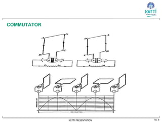


The document discusses the working principle of a DC generator. It explains that a DC generator converts mechanical energy to electrical energy using electromagnetic induction. When a conductor moves through a magnetic field, an induced current is generated based on Faraday's law of induction. The direction of the induced current can be determined using Fleming's right hand rule. The document then describes how a rectangular loop of conductor rotating inside a magnetic field cuts the magnetic flux, generating an induced current that changes direction based on the loop's position. A commutator is used to ensure the output current flows continuously in one direction to the load.


![Chapter 4 dc machine [autosaved]](https://cdn.slidesharecdn.com/ss_thumbnails/chapter4-dcmachineautosaved-140915220206-phpapp01-thumbnail.jpg?width=640&height=640&fit=bounds)


