Downloaded 52 times


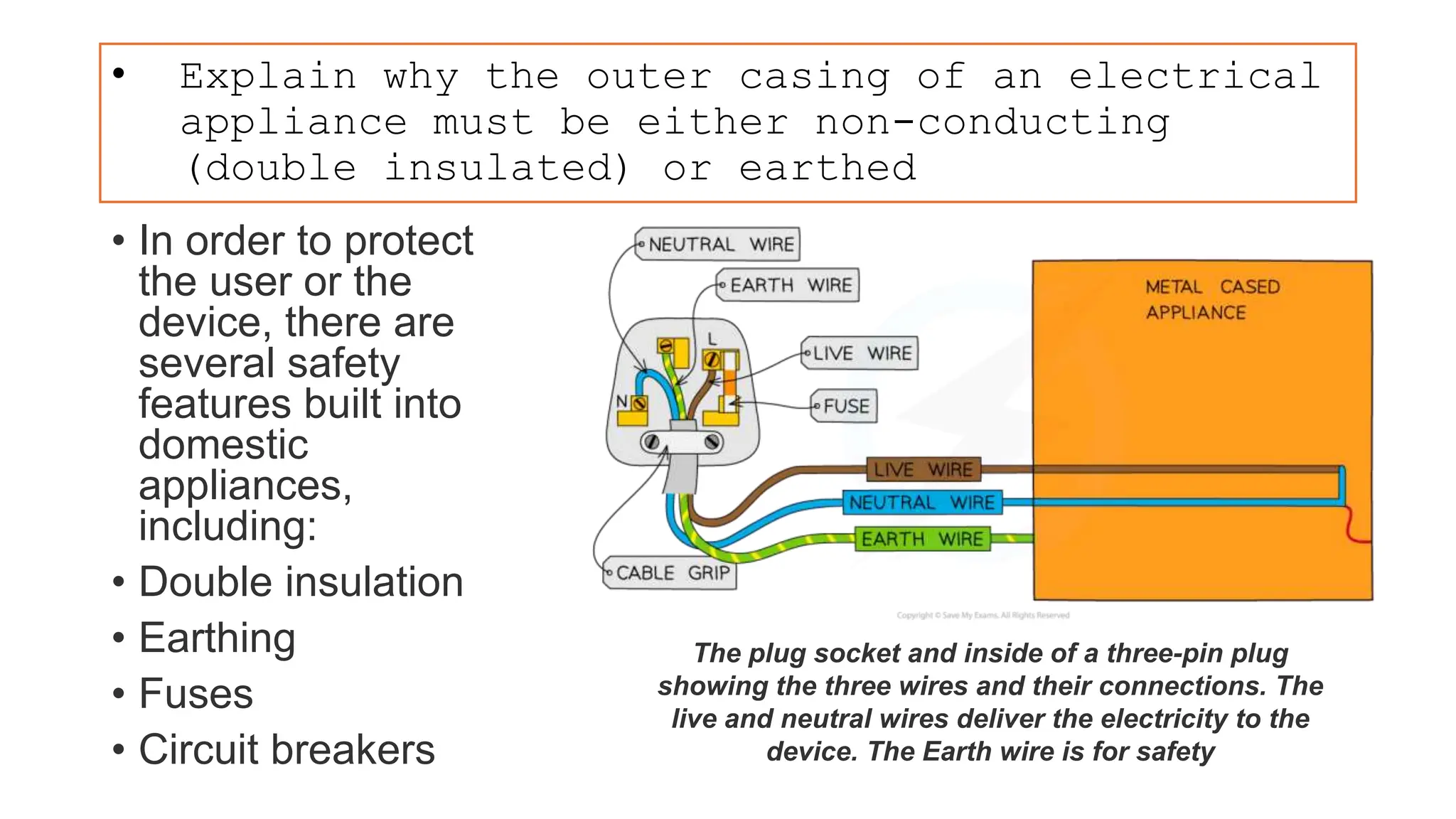


- Mains electricity consists of a live wire, neutral wire, and earth wire. The switch must be connected to the live wire to safely cut off the circuit. - Electrical appliances must have either non-conducting double insulation or an earthed metal casing. This prevents electrocution if the live wire contacts the casing. - Common electrical hazards include damaged insulation, overheating cables, damp conditions, and overloading plugs/sockets which can cause fires. Mains electricity poses lethal shock risks.
Overview of the circuit topic to be discussed.
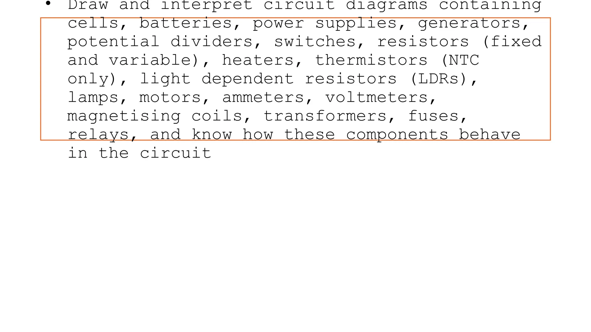
Discusses various circuit components like cells, batteries, switches, resistors, and electromagnetic parts, their functions and behaviors.
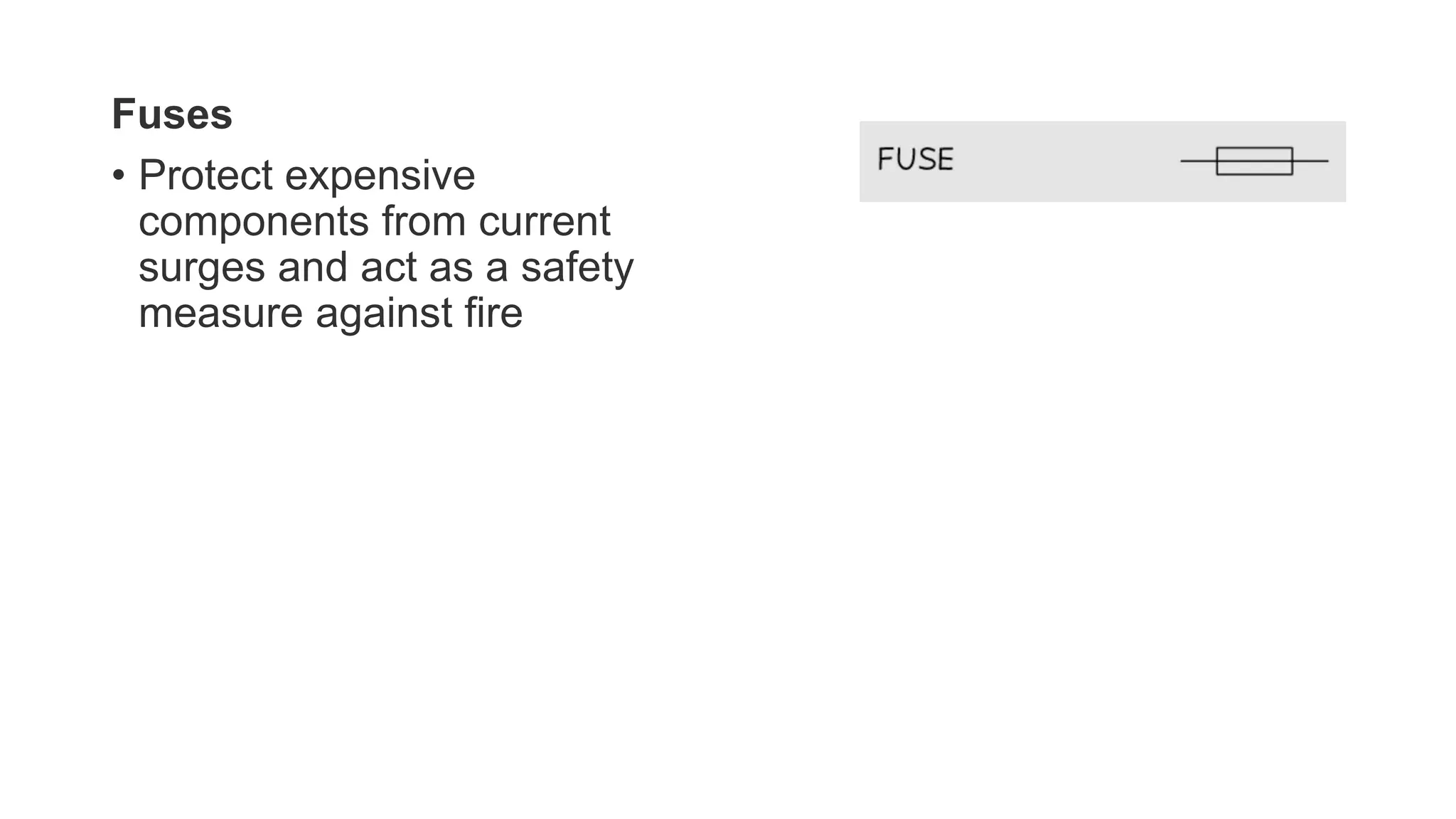
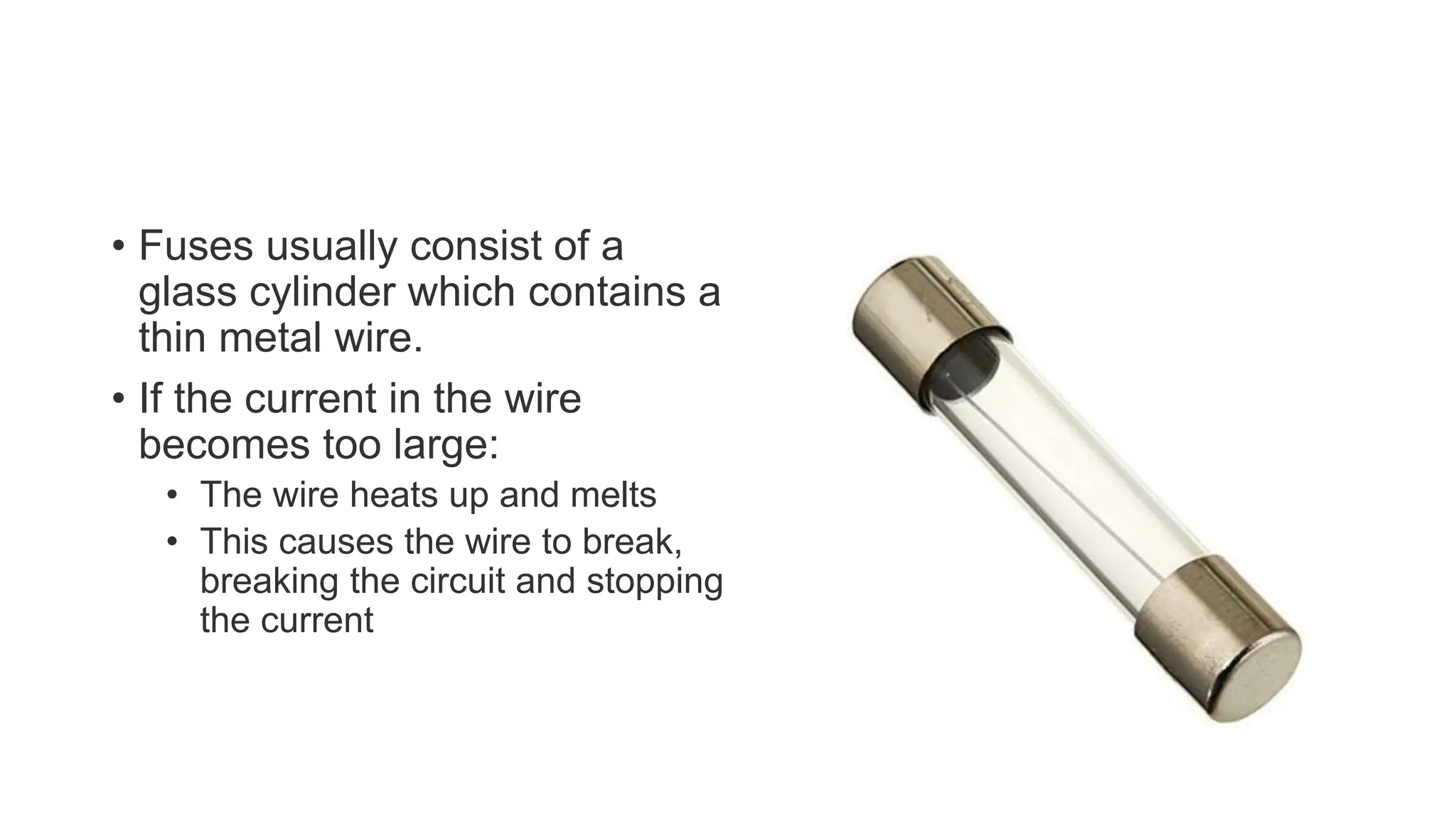
Introduces fuses, their role in protecting expensive components and providing safety against fire.
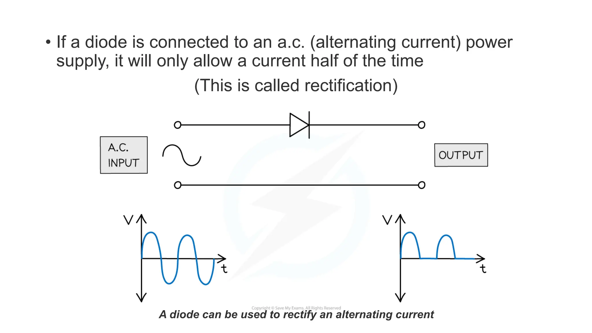
Describes diodes, their function to allow current in one direction, and basic rectification.
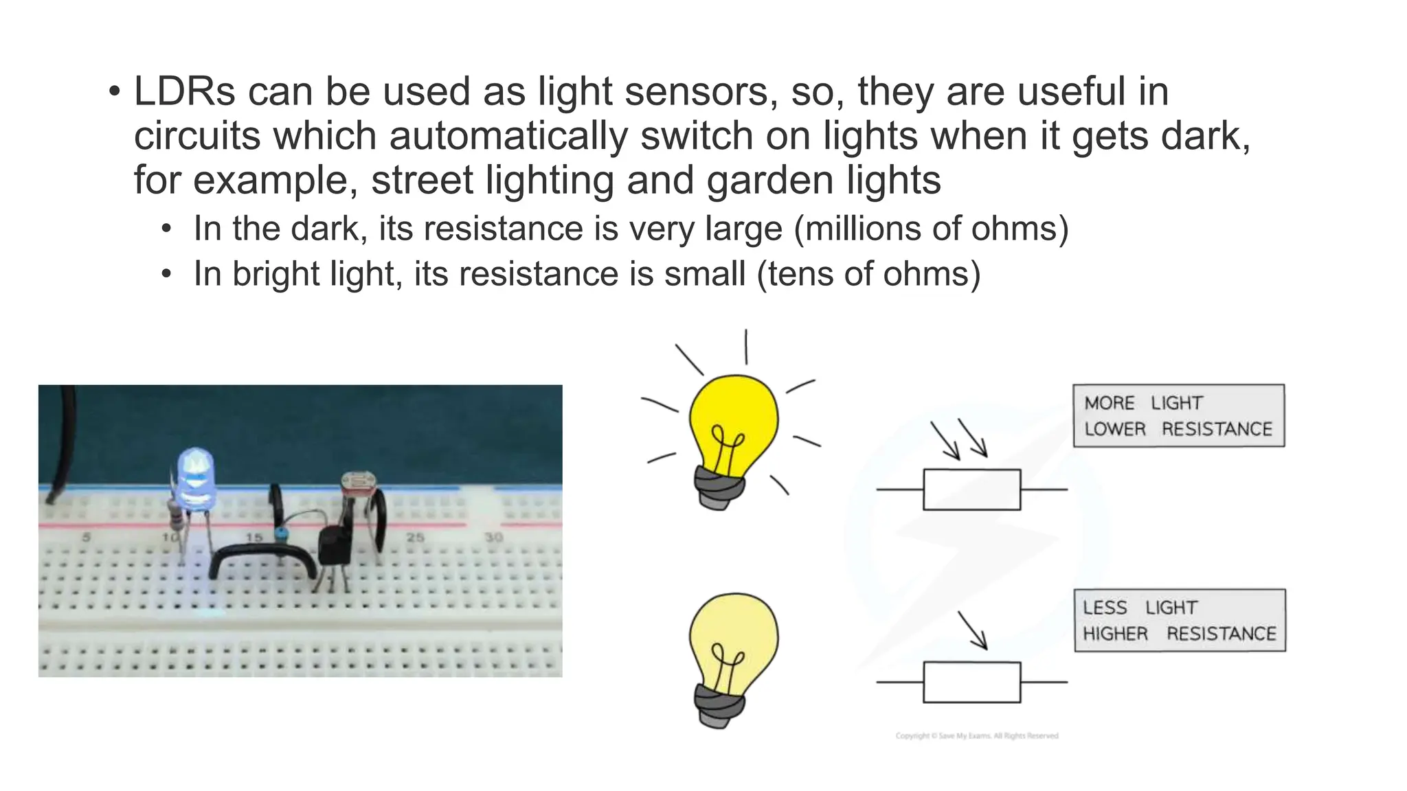
Focuses on the characteristics of light-dependent resistors (LDRs), their sensory functions, and resistance changes.
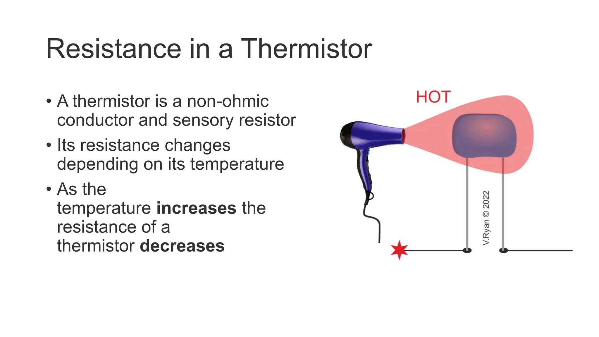
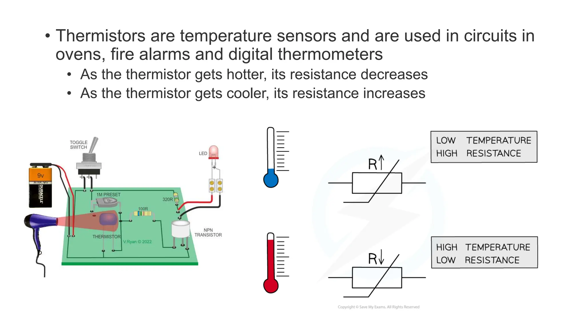
Studies thermistors, their temperature-dependent resistance changes, and applications in sensors.
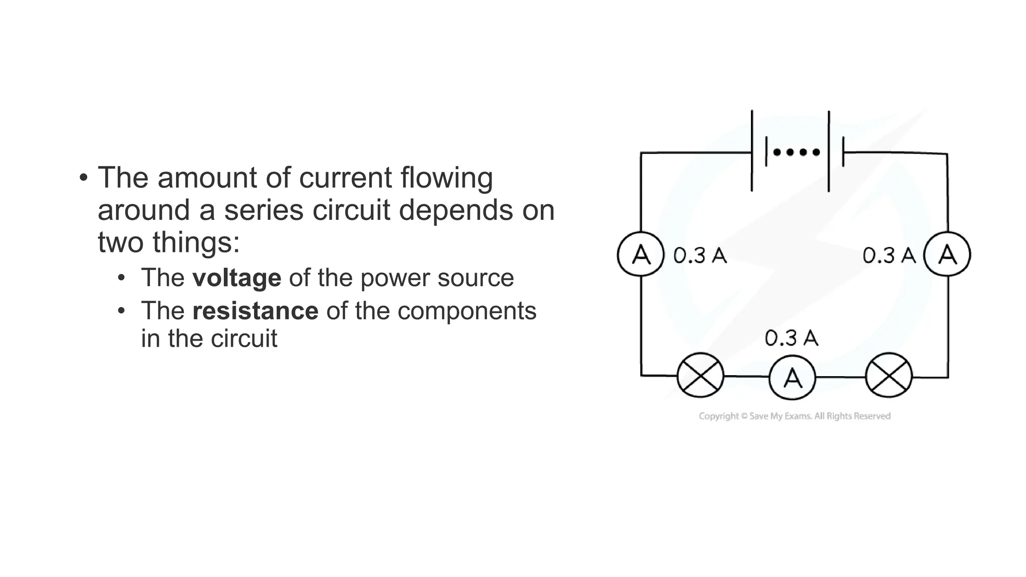
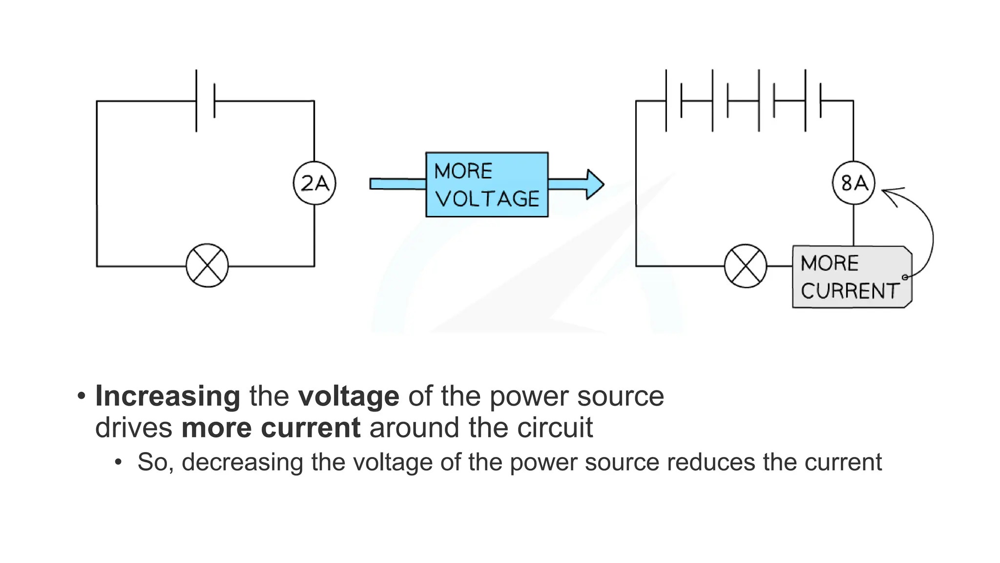
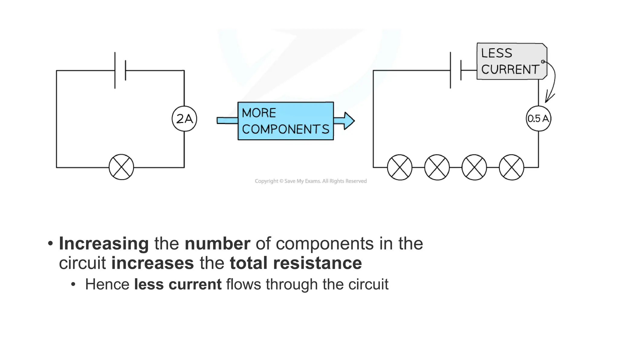
Explains series circuits, current consistency, voltage considerations, and how resistance affects current flow.
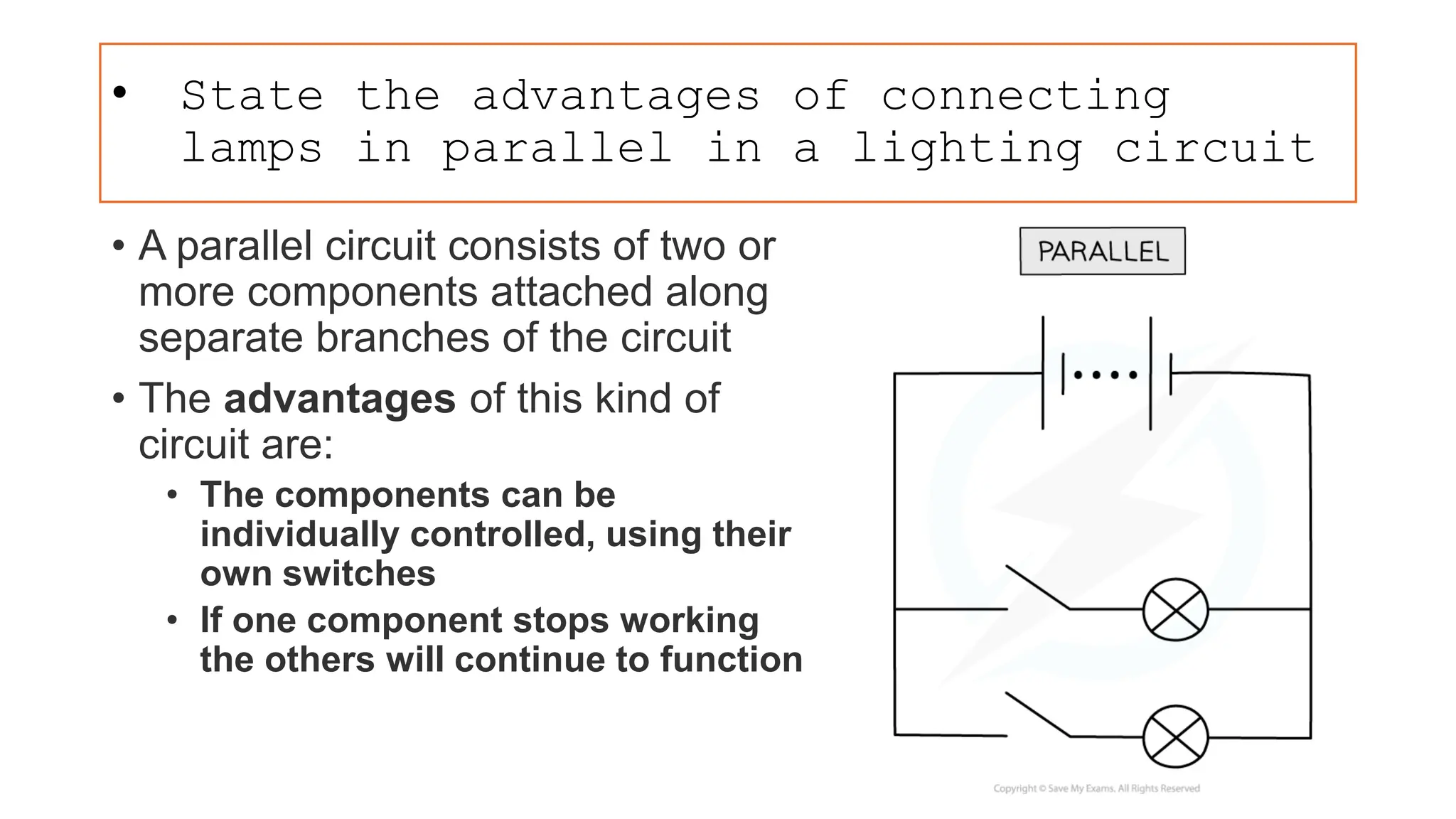
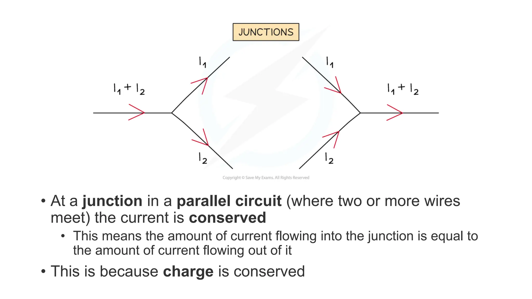
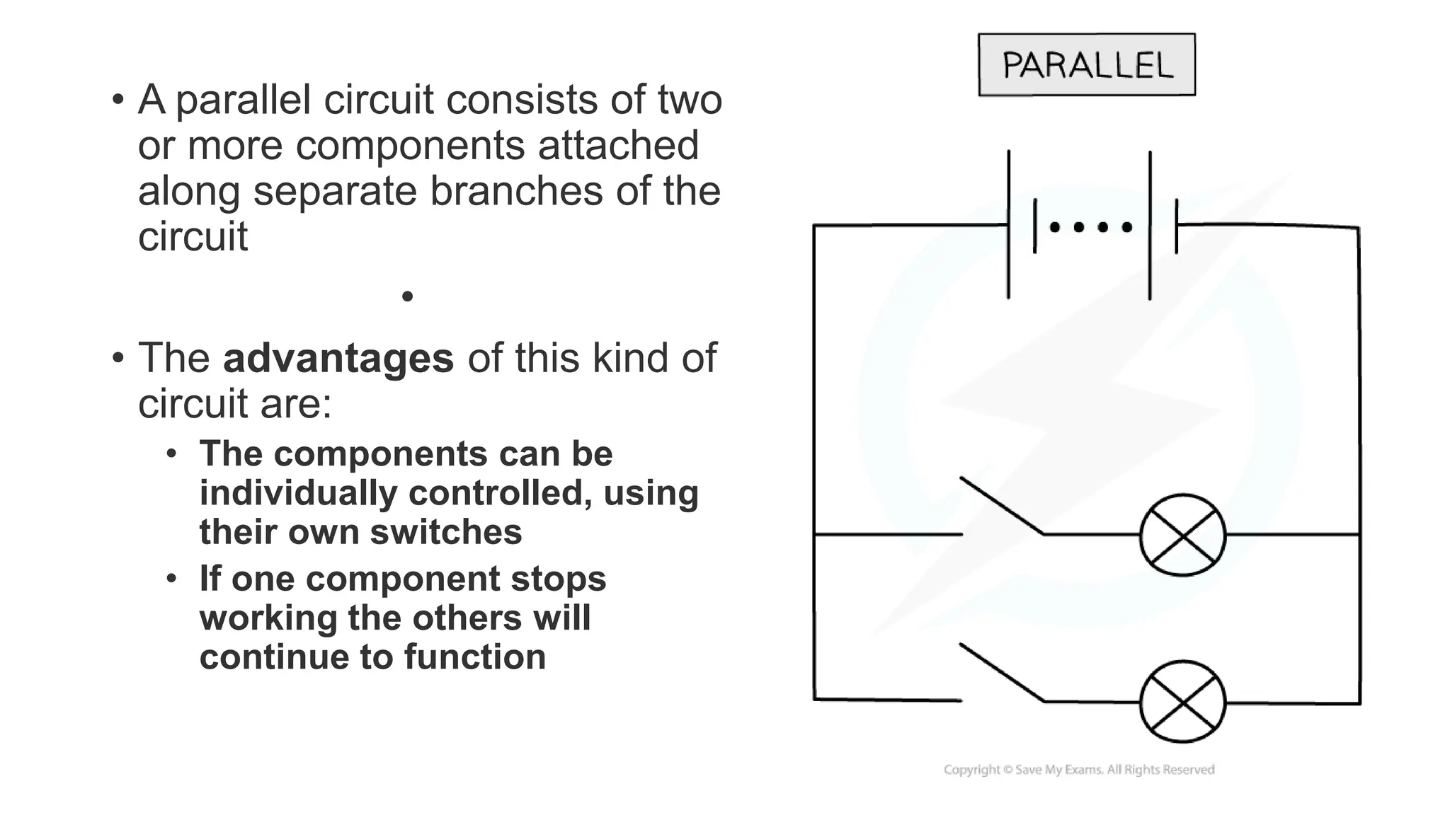
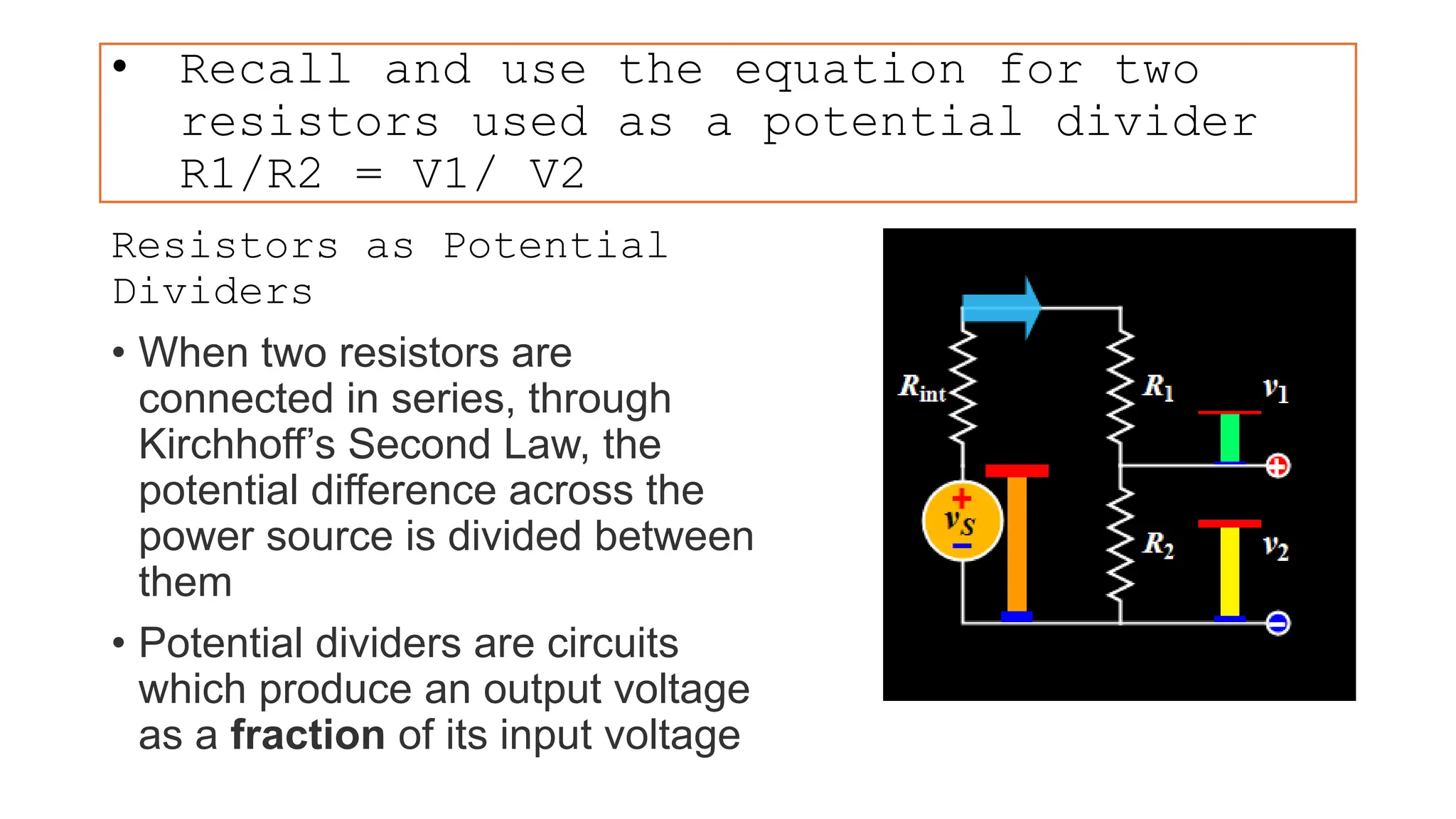
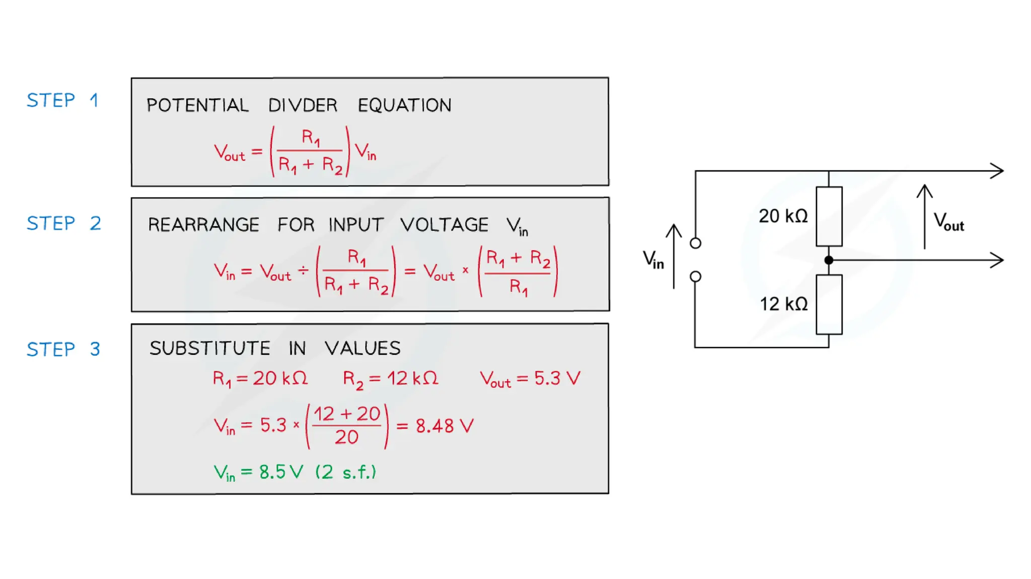
Describes parallel circuits, their benefits, current splitting, and the concept of current conservation.Examines potential difference across series and parallel circuits and how it is distributed among components. Focuses on variable potential dividers, their function, equations, and widespread usage in devices.
Details how energy is transferred from power sources through circuits to appliances, using various examples.
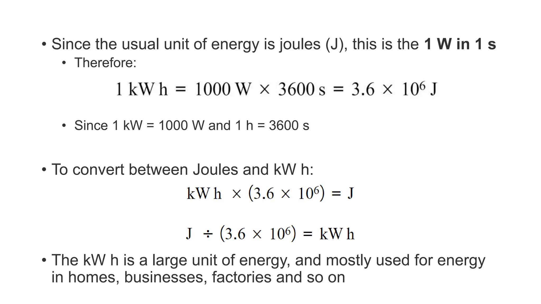
Defines electrical power and energy, equations, calculations for energy consumption in appliances.
Defines electrical power and energy, equations, calculations for energy consumption in appliances.
Discusses common electrical hazards associated with mains electricity and safety features like insulation.
Discusses common electrical hazards associated with mains electricity and safety features like insulation.
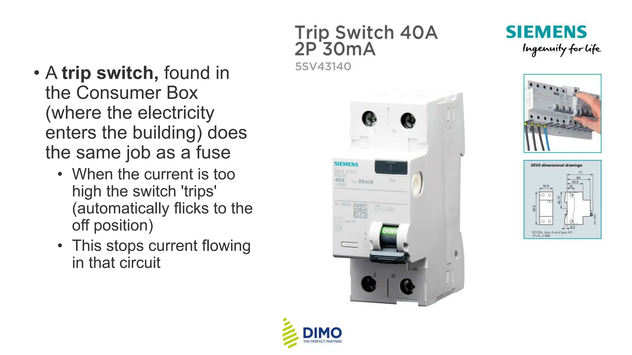
Explains safety measures like earthing, fuses, and trip switches to prevent electrical hazards.