Download to read offline
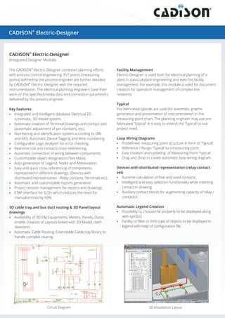
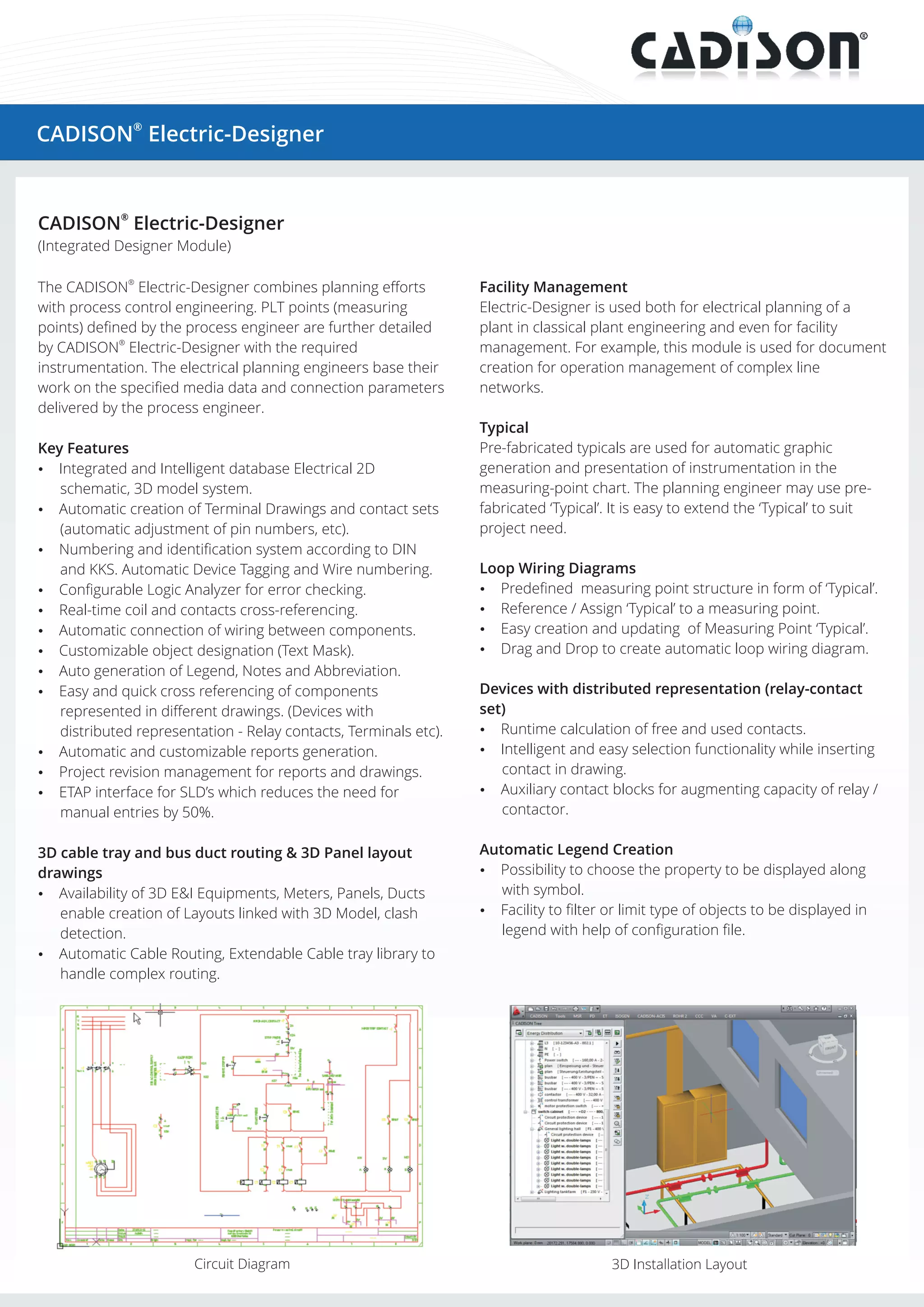
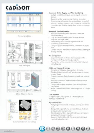

The CADISON® Electric-Designer module combines electrical planning with process control engineering. It allows process engineers to define measurement points which are then detailed with required instrumentation by electrical planners. Key features include integrated 2D/3D modeling, automatic numbering, terminal drawings, loop wiring diagrams, pre-defined instrument "typicals", and report generation. The software can be used for both new plant engineering and existing facility management.


