The document describes CADISON Pipe Support Modeler, which allows users to easily create and edit secondary pipe supports. It provides predefined support types and enables customization of supports through options like profile orientation, offset, insertion points, and editing of existing supports. The software includes features for clash detection, bill of materials generation, rendering, and creating hookup drawings of supports. It aims to improve productivity for modeling secondary pipe supports.
Pipe Support Modeler assists the user to create and edit the secondary supports in an easy and intelligent manner. Assistant Secondary Support features enable the user to create multiple and different types of supports from predefined supports. A user-friendly GUI provides flexibility by allowing the user to create variations in predefined type of supports during the data entry stage for e.g. offset,orientation and industry validations. Supports created using ‘Create Support’ wizard are both constructible and erectable.
nanoCAD construction- a construction drawing softwarenanoCAD India
nanoCAD’s Construction module extends the nanoCAD platform with AEC drafting utilities and a library of standard parametric elements. It is designed to automate the preparation of construction drawings and documentation.
New in Construction
BCF
Other improvements
Woodwork for Inventor V8 is finally launched. Take a look at we did this year. Here you'll find a description of many improvements and two totally new features.
ISOMEC is automated, rule-based, and specification driven according to the industry standard. Various Thickness Calculations as per ASME 31.1, 31.3, 31.4. Valve Material Sheet generation, Initial/estimated MTO, as well as various reports generation like PMS, VMS, Thickness Calculation, Spec Index, etc.
It is also used for making automatic Piping Isometric drawings, Piping Spool drawings, the Bill of materials, and reporting from the outline of isometric. This specific piping drawing application for Piping Engineering takes care of the complete Isometric drawing and related documents and deliverables.
ISOMEC helps in achieving the maximum standardization, resulting in greater productivity and profitability.
ISOMEC is having feature to draw FireFighting Drawing Routing
Highlights
Catalogue ASME B16.9/ B16.11 etc.
Itemcode generation as per the catalogue Item
Calculation as per B31.3 (Piping) / B31.4 (Pipeline)
Piping Material Specification (PMS)
Valve Material Sheet (VMS)
Initial or Estimated MTO
Generation of piping ISOMETRIC from Outline of Iso’s
Interface with third party application’s
Enhance your engineering design process with PTC Creo Illustrate, the leading 3D CAD illustration software. Effortlessly convert CAD data into dynamic 3D animations and interactive illustrations that accurately highlight your product's engineering details. With Creo Illustrate, smoothly communicate complex CAD information, improving collaboration and understanding among teams and stakeholders. Explore the world of 3D technical illustrations and animations with Creo Illustrate today.
"Understand the concept of Revit detailing drawings. As generating a good set of construction, drawings play an essential factor for making the excellent model of BIM (Building Information Modeling)
Cubikcadd offers CATIA course training in Gandhipuram. We provide training in both the classroom and online training. For more details contact: 9500024134
MockupUI is a user interface mockup and wireframing software. It helps software designers and developers to quickly turn ideas into UI mockups and produce design specification documents.
Streamlining the Design of Industrial Machinery and Heavy EquipmentEngineering Technique
In today’s increasingly competitive global market, manufacturers of industrial machinery or heavy equipment face daunting development challenges. The need to accelerate product time-to-market, control costs, and improve product complexity requires that you modernize your product development systems and implement 3D-based design technologies. Taking advantage of a 3D CAD environment enables you to outpace competitors by developing and producing better machines in a shorter time - and at a lower cost.
SolidWorks software provides the tools and capabilities that you need to transition quickly to 3D. After moving from 2D CAD to SolidWorks software, many manufacturers soon realize productivity gains at every stage of the development process. In this way, manufacturers can quickly realize a return on their SolidWorks software investment. Typically, first-year benefits include decreased development time, lower development costs, and reduced design errors. SolidWorks software offers you a complete 3D CAD design solution that can ultimately help you increase profit margins, improve product quality, and raise customer satisfaction.
CADISON® combines the engineering workflow in one system and thus significantly accelerates the plant design processes.
The common object-oriented data model for the different fields of application (tender planning, process engineering, installation planning, pipeline planning, electrical engineering, instrumentation etc.) makes it possible to integrate all planning phases so that time and costs are saved. CADISON® serves to collect valuable information in the tendering phase already so that staff members have the required data available in all later phases of project handling.
CADISON® Project Engineer is your tool for plant design, Engineering calculations and detailing of your plant by adding all required components (objects) to the project while taking them from the catalogue. Simple Drag & Drop operations are sufficient with completely text based operations without the obligation to have a graphical environment.
CADISON® Project Engineer is your tool for plant design, Engineering calculations and detailing of your plant by adding all required components (objects) to the project while taking them from the catalogue. Simple Drag & Drop operations are sufficient with completely text based operations without the obligation to have a graphical environment. This approach is called "Conceptual Engineering". The target of CADISON® Project Engineer is to provide the user with data for calculation without large efforts and already at a very early time.
Installation and pipeline planning in the 3D model are in the competence of the 3D Designer. Normally this module is used for access to data from Basic Engineering or P&ID. Efficient assistants are available for installation planning: For instance, isometrics can be automatically generated from the planned pipeline systems.
The CADISON® P&ID Designer plays a decisive role in design, construction, commissioning and maintenance and has an enormous effect on the complete lifecycle of a plant. In this case the preliminary project engineering will be integrated with Basic and Detail Engineering and 2D layout planning. Apart from the P&I diagrams the P&ID Designer even creates block flow charts and process flow diagrams (PFD).
CADISON® Project Navigator is the module for viewing of project data within the corporate network. Navigator has been designed for staff members normally not involved in the active planning of a plant but afterwards responsible for operation and maintenance of the plant (i.e. mere data consumers).
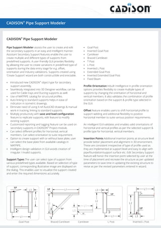
1. ®
CADISON Pipe Support Modeler
CADISON® Pipe Support Modeler
Pipe Support Modeler assists the user to create and edit
the secondary supports in an easy and intelligent manner.
Assistant Secondary Support features enable the user to
create multiple and different types of supports from
predefined supports. A user-friendly GUI provides flexibility
by allowing the user to create variations in predefined type of
supports during the data entry stage for e.g. offset,
orientation and industry validations. Supports created using
‘Create Support’ wizard are both constructible and erectable.
?
Goal Post
? Goal Post
Inverted
?
Cantilever
? Cantilever
Braced
?
T Post
?
L Post
? L Post
Inverted
?
Extended Goal Post
? Extended Goal Post
Inverted
?
Fixed Beam
®
?
Introduced new CADISON object type for secondary
support assembly.
?
Seamlessly integrated into 3D Designer workflow, can be
used for Cable trays and Ducting supports as well.
?MATPIPE catalog for structural profiles.
Use of
?
Auto linking to standard supports helps in ease of
indication in isometric drawings.
Profile Orientation Inbuilt intelligence in profile orientation
options provides flexibility to create multiple types of
supports by changing the orientation of horizontal and
vertical members. It also validates the combination of profile
orientation based on the support & profile type selected in
the GUI.
? need of using X-ref AutoCAD drawings & manual
Eliminate
work in tracking, linking to standard supports.
? productivity with save and load configuration
Multiply
feature to replicate supports, edit feature to modify
existing support.
?
Customized reporting and tagging feature can be used on
secondary supports in CADISON® Project module.
?
Can select different profiles for horizontal, vertical
members. Can select orientation to suite requirement.
? to create support with or without base plate, user
Option
can select the base plate from available catalogs in
MATPIPE.
?
Intelligent design validation in GUI avoids creation of
irregular / invalid supports.
Support Types The user can select type of support from
various predefined types available. Based on selection of type
of support, corresponding illustrative image are displayed on
the dialog. This enables user to visualize the support created
and enter the required dimensions accurately.
Goal Post
Braced Cantilever
Offset feature enables users to shift horizontal profile to
support welding and additional flexibility to position
horizontal member to suite various position requirements.
An intelligent GUI validates and enables valid orientations of
horizontal and vertical profiles as per the selected support &
profile type for horizontal, vertical members.
Insertion Points Additional insertion points at structure level
provide better placement and alignment in 3D environment.
These are consistent irrespective of type of profile used as
they are implemented at support level and easy to align with
pipe/foundation/support surface etc. Edit Secondary Support
feature will honor the insertion point selected by user at the
time of placement and recreate the structure as per updated
parameters to save time in updating the existing structure to
revise as per the revised parameters entered in wizard.
Cantilever
L Post
Inverted L Post
2. ?
Clash detection & Bill of Material (BOM)
?
Rendering and interference detection
? visualization helps in efficient modeling of
Real time
Secondary Supports to avoid potential interference with
other plant objects
?
BOM specific to plant area
?
BOM based on type of supports
?
BOM based on profile types
Edit Secondary Support
This feature enables the user to modify the existing support
in an easy manner. The edit feature recognizes the support
created using create support wizard. It will fetch the
parameters entered at the time of creation of support. Edit
feature will honor the insertion point selected by user at the
time of placement and recreate the structure as per updated
parameters. User can also add/remove base plate from
existing support.
Apart from maintaining backward compatibility, the Edit
Secondary Support feature enables the user to select the
structure created in previous versions to recreate as per the
additional validations incorporated in the latest version.
Report Generation
? generation feature of CADISON can be used to
Report
generate list of supports at project level, in drawings etc.
? individual support or selected supports with in
BOM of
drawing can be generated.
?
All reports can be stored in the CADISON document
management with an active revision management system.
? to create reports in background allows generating
Facility
reports without interrupting design process.
? MS Word, Excel & PDF, generate multilingual
Supports
reports (English, German).
Hookup drawing
Hookup drawing feature enables the user to create automatic
production drawings of selected type of support/s. The user
can create hookup drawing for selected secondary support
as well as multiple supports of a specific type.
Each type of support has specific drawing template with
predefined typical to represent dimensions. There is a
provision to revise or replace typical to be displayed in
hookup drawing to suite organization needs and increase
adaptability for changing requirements of projects.
Number of columns and rows in hookup drawing table can
be configured in drawing templates. User can rearrange or
decide the number of columns of table as per organization
needs.
www.cadison.com