Download to read offline
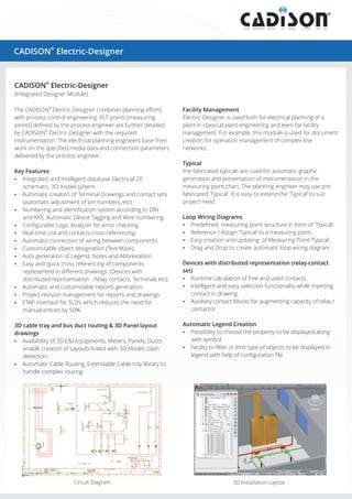
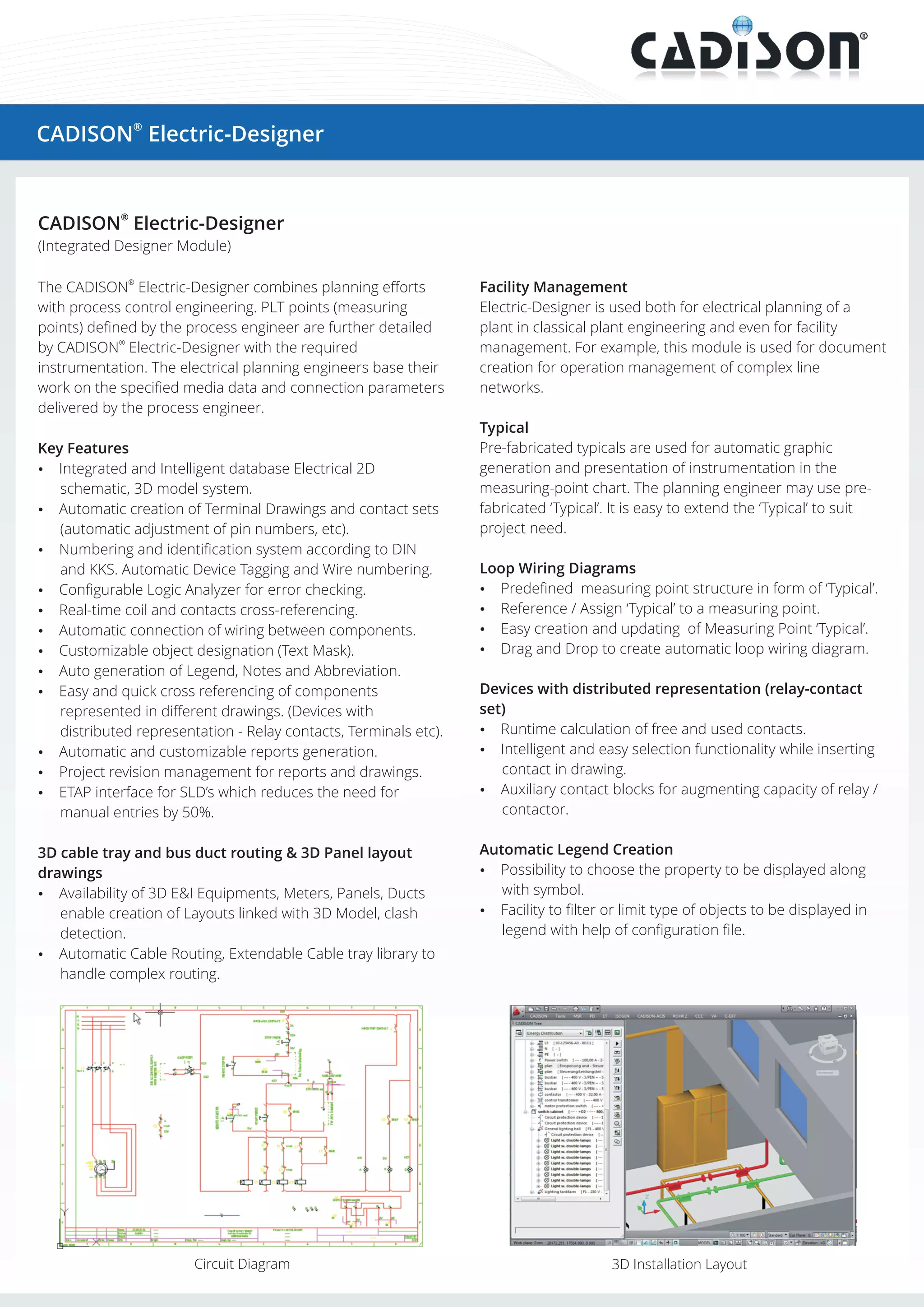
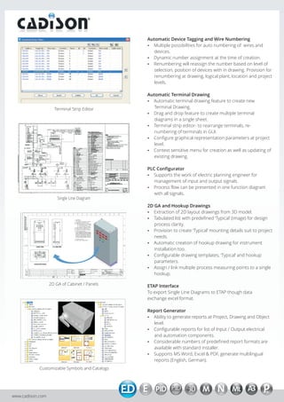

The Cadison Electric-Designer integrates electrical planning with process control, providing features like automatic generation of diagrams, device tagging, and customizable reports. It facilitates 3D layouts, real-time error checking, and improved project management, enhancing efficiency for both plant engineering and facility management. The software's intelligent database allows for easy updates, drag-and-drop design, and export to various formats, supporting a wide array of electrical planning tasks.


