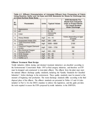
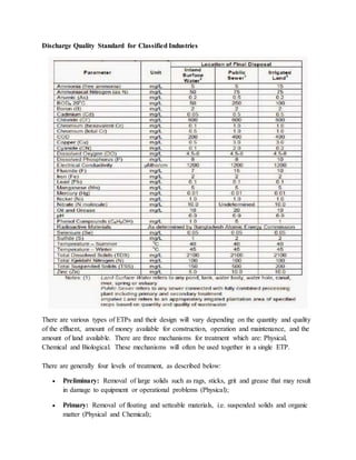
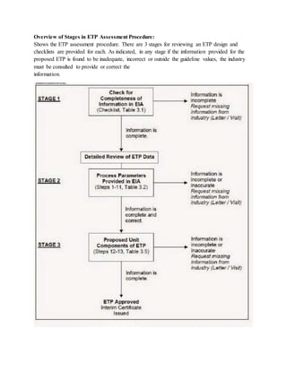
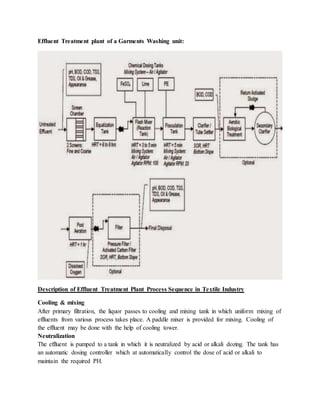
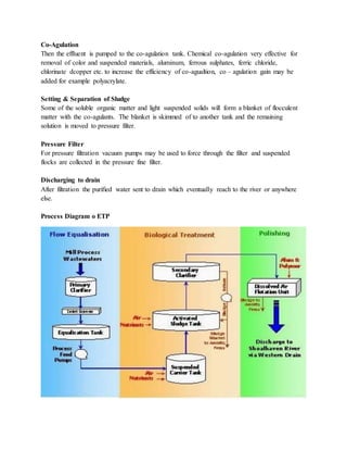
The document summarizes the process of an effluent treatment plant for treating wastewater from textile and dyeing industries. It describes the various stages of treatment including neutralization, coagulation, sedimentation, filtration and disinfection. Key points of the process include using chemicals like alum and lime to coagulate solids, clarifiers to separate treated water from sludge, and a filter press to dewater the sludge for safe disposal. The goal is to reduce pollutants in the effluent like BOD, COD and color to meet discharge standards before releasing the treated water.
Effluent Treatment Plant Design, Operation And Analysis Of Waste Water Jaidev Singh
Contents
1. Introduction to Effluent Treatment Plant (ETP)
1.1 Use of water in industries
1.2 Industrial waste water sources
1.3 Effluent Treatment Plant
1.4 National Standards for waste water
1.5 What do these standards means?
1.6 Waste water treatment
1.7 Planning an Effluent Treatment Plant : Factors to Consider
2. Treatment Methods
2.1 Physical Unit Operations
2.2 Chemical Unit Processes
2.3 Biological Unit Processes
3. Operation and control
3.1 Mixed liquor suspended solids
3.2 Sludge Volume Index and Sludge Density Index
3.3 Sludge Age; Mean Cell Residence Time (MCRT)
3.4 Food/Mass Ratio
3.5 Constant MLSS
3.6 Return Activated Sludge Control (RAS)
4. Choosing an Effluent Treatment Plant
4.1 Biological Treatment
4.2 Physico-Chemical Treatment
4.3 Physico-Chemical and Biological Treatment
4.4 Area Requirement Comparison
4.5 Cost Comparison
5. Chemical Analysis of Waste Water
5.1 Commonly used chemicals
5.2 Chemical Tests and procedures
Textile dyeing industry: wastewater treatment and managementMd. Shamim Ahmed
small overview on wastewater treatment and management made by my brother(Roni Das) from another mother. I helped him to made this because he is greenhorn about power point presentation.
Lecture notes of Industrial Waste Treatment (Elective -III) as per syllabus of Solapur university for BE Civil
Prepared by
Prof S S Jahagirdar,
Associate Professor,
N K ORchid College of Engg and Tech,
Solapur
Dairy waste water treatmentby arhana gautamarchana gautam
The dairy industry involves processing raw milk into products such as consumer milk, butter, cheese, yogurt, condensed milk, dried milk (milk powder), and ice cream, using processes such as chilling, pasteurization, and homogenization. Typical by-products include buttermilk, whey, and their derivatives. Dairy industries have shown tremendous growth in size and number inmost countries of the world . These industries discharge wastewater which is characterized by high chemical oxygen demand, biological oxygen demand, nutrients, and organic and inorganic contents. Such wastewaters, if discharged without proper treatment, severely pollute receiving water bodies.
Dairy processing plants can be divided into two categories:
Fluid milk processing involving the pasteurization and processing of raw milk into liquid milk for direct consumption, as well as cream, flavored milk, and fermented products such as buttermilk and yogurt.
Industrial milk processing involving the pasteurization and processing of raw milk into value-added dairy products such as cheese and casein, butter and other milk fats, milk powder and condensed milk, whey powder and other dairy ingredients, and ice cream and other frozen dairy products.
Food processing industry is estimated at USD 67 Billion that employs over 13 million people directly and 35 million people indirectly. This presentation includes key growth drivers,opportunities, key segments, foreign investments and what the Make In India program has for food processing industry of India .
This document is a PDF version of my soil analysis research project presentation I gave on 6 August 2008. Field work for this project involved selected sites in the Cleveland Botanical Garden’s Woodland Garden and was conducted during the summer of 2008.
Effluent Treatment Plant
What is ETP
Need fo ETP
Design of ETP
Design of ETP
Sludge treatment process
Flowchart of ETP
Case study of ETP
ETP plant operation
Textile plant ETP
Equalization
Sedimentation
Settlers
Sludge treatment process
Flowchart of ETP
Case study of ETP
ETP plant operation
Textile plant ETP
Equalization
Sedimentation
Settlers
PH adjustment
Here at ACE DYNAMICS, our innovative, sustainable solutions help our clients to address their Air, Water, Environment, Energy, and Resource management challenges.
Details ppt on Effluent Treatment Plant or ETP for M Pharm.
In this Presentation we discuss about defination , design , need , Mechanism and many more important things related to ETP.
Share it with your friends.
Thank You.
Student information management system project report ii.pdfKamal Acharya
Our project explains about the student management. This project mainly explains the various actions related to student details. This project shows some ease in adding, editing and deleting the student details. It also provides a less time consuming process for viewing, adding, editing and deleting the marks of the students.
Water scarcity is the lack of fresh water resources to meet the standard water demand. There are two type of water scarcity. One is physical. The other is economic water scarcity.
Cosmetic shop management system project report.pdfKamal Acharya
Buying new cosmetic products is difficult. It can even be scary for those who have sensitive skin and are prone to skin trouble. The information needed to alleviate this problem is on the back of each product, but it's thought to interpret those ingredient lists unless you have a background in chemistry.
Instead of buying and hoping for the best, we can use data science to help us predict which products may be good fits for us. It includes various function programs to do the above mentioned tasks.
Data file handling has been effectively used in the program.
The automated cosmetic shop management system should deal with the automation of general workflow and administration process of the shop. The main processes of the system focus on customer's request where the system is able to search the most appropriate products and deliver it to the customers. It should help the employees to quickly identify the list of cosmetic product that have reached the minimum quantity and also keep a track of expired date for each cosmetic product. It should help the employees to find the rack number in which the product is placed.It is also Faster and more efficient way.
Courier management system project report.pdfKamal Acharya
It is now-a-days very important for the people to send or receive articles like imported furniture, electronic items, gifts, business goods and the like. People depend vastly on different transport systems which mostly use the manual way of receiving and delivering the articles. There is no way to track the articles till they are received and there is no way to let the customer know what happened in transit, once he booked some articles. In such a situation, we need a system which completely computerizes the cargo activities including time to time tracking of the articles sent. This need is fulfilled by Courier Management System software which is online software for the cargo management people that enables them to receive the goods from a source and send them to a required destination and track their status from time to time.
About
Indigenized remote control interface card suitable for MAFI system CCR equipment. Compatible for IDM8000 CCR. Backplane mounted serial and TCP/Ethernet communication module for CCR remote access. IDM 8000 CCR remote control on serial and TCP protocol.
• Remote control: Parallel or serial interface.
• Compatible with MAFI CCR system.
• Compatible with IDM8000 CCR.
• Compatible with Backplane mount serial communication.
• Compatible with commercial and Defence aviation CCR system.
• Remote control system for accessing CCR and allied system over serial or TCP.
• Indigenized local Support/presence in India.
• Easy in configuration using DIP switches.
Technical Specifications
Indigenized remote control interface card suitable for MAFI system CCR equipment. Compatible for IDM8000 CCR. Backplane mounted serial and TCP/Ethernet communication module for CCR remote access. IDM 8000 CCR remote control on serial and TCP protocol.
Key Features
Indigenized remote control interface card suitable for MAFI system CCR equipment. Compatible for IDM8000 CCR. Backplane mounted serial and TCP/Ethernet communication module for CCR remote access. IDM 8000 CCR remote control on serial and TCP protocol.
• Remote control: Parallel or serial interface
• Compatible with MAFI CCR system
• Copatiable with IDM8000 CCR
• Compatible with Backplane mount serial communication.
• Compatible with commercial and Defence aviation CCR system.
• Remote control system for accessing CCR and allied system over serial or TCP.
• Indigenized local Support/presence in India.
Application
• Remote control: Parallel or serial interface.
• Compatible with MAFI CCR system.
• Compatible with IDM8000 CCR.
• Compatible with Backplane mount serial communication.
• Compatible with commercial and Defence aviation CCR system.
• Remote control system for accessing CCR and allied system over serial or TCP.
• Indigenized local Support/presence in India.
• Easy in configuration using DIP switches.
Final project report on grocery store management system..pdfKamal Acharya
In today’s fast-changing business environment, it’s extremely important to be able to respond to client needs in the most effective and timely manner. If your customers wish to see your business online and have instant access to your products or services.
Online Grocery Store is an e-commerce website, which retails various grocery products. This project allows viewing various products available enables registered users to purchase desired products instantly using Paytm, UPI payment processor (Instant Pay) and also can place order by using Cash on Delivery (Pay Later) option. This project provides an easy access to Administrators and Managers to view orders placed using Pay Later and Instant Pay options.
In order to develop an e-commerce website, a number of Technologies must be studied and understood. These include multi-tiered architecture, server and client-side scripting techniques, implementation technologies, programming language (such as PHP, HTML, CSS, JavaScript) and MySQL relational databases. This is a project with the objective to develop a basic website where a consumer is provided with a shopping cart website and also to know about the technologies used to develop such a website.
This document will discuss each of the underlying technologies to create and implement an e- commerce website.
Sachpazis:Terzaghi Bearing Capacity Estimation in simple terms with Calculati...Dr.Costas Sachpazis
Terzaghi's soil bearing capacity theory, developed by Karl Terzaghi, is a fundamental principle in geotechnical engineering used to determine the bearing capacity of shallow foundations. This theory provides a method to calculate the ultimate bearing capacity of soil, which is the maximum load per unit area that the soil can support without undergoing shear failure. The Calculation HTML Code included.
Automobile Management System Project Report.pdfKamal Acharya
The proposed project is developed to manage the automobile in the automobile dealer company. The main module in this project is login, automobile management, customer management, sales, complaints and reports. The first module is the login. The automobile showroom owner should login to the project for usage. The username and password are verified and if it is correct, next form opens. If the username and password are not correct, it shows the error message.
When a customer search for a automobile, if the automobile is available, they will be taken to a page that shows the details of the automobile including automobile name, automobile ID, quantity, price etc. “Automobile Management System” is useful for maintaining automobiles, customers effectively and hence helps for establishing good relation between customer and automobile organization. It contains various customized modules for effectively maintaining automobiles and stock information accurately and safely.
When the automobile is sold to the customer, stock will be reduced automatically. When a new purchase is made, stock will be increased automatically. While selecting automobiles for sale, the proposed software will automatically check for total number of available stock of that particular item, if the total stock of that particular item is less than 5, software will notify the user to purchase the particular item.
Also when the user tries to sale items which are not in stock, the system will prompt the user that the stock is not enough. Customers of this system can search for a automobile; can purchase a automobile easily by selecting fast. On the other hand the stock of automobiles can be maintained perfectly by the automobile shop manager overcoming the drawbacks of existing system.
Saudi Arabia stands as a titan in the global energy landscape, renowned for its abundant oil and gas resources. It's the largest exporter of petroleum and holds some of the world's most significant reserves. Let's delve into the top 10 oil and gas projects shaping Saudi Arabia's energy future in 2024.
COLLEGE BUS MANAGEMENT SYSTEM PROJECT REPORT.pdfKamal Acharya
The College Bus Management system is completely developed by Visual Basic .NET Version. The application is connect with most secured database language MS SQL Server. The application is develop by using best combination of front-end and back-end languages. The application is totally design like flat user interface. This flat user interface is more attractive user interface in 2017. The application is gives more important to the system functionality. The application is to manage the student’s details, driver’s details, bus details, bus route details, bus fees details and more. The application has only one unit for admin. The admin can manage the entire application. The admin can login into the application by using username and password of the admin. The application is develop for big and small colleges. It is more user friendly for non-computer person. Even they can easily learn how to manage the application within hours. The application is more secure by the admin. The system will give an effective output for the VB.Net and SQL Server given as input to the system. The compiled java program given as input to the system, after scanning the program will generate different reports. The application generates the report for users. The admin can view and download the report of the data. The application deliver the excel format reports. Because, excel formatted reports is very easy to understand the income and expense of the college bus. This application is mainly develop for windows operating system users. In 2017, 73% of people enterprises are using windows operating system. So the application will easily install for all the windows operating system users. The application-developed size is very low. The application consumes very low space in disk. Therefore, the user can allocate very minimum local disk space for this application.
Event Management System Vb Net Project Report.pdfKamal Acharya
In present era, the scopes of information technology growing with a very fast .We do not see any are untouched from this industry. The scope of information technology has become wider includes: Business and industry. Household Business, Communication, Education, Entertainment, Science, Medicine, Engineering, Distance Learning, Weather Forecasting. Carrier Searching and so on.
My project named “Event Management System” is software that store and maintained all events coordinated in college. It also helpful to print related reports. My project will help to record the events coordinated by faculties with their Name, Event subject, date & details in an efficient & effective ways.
In my system we have to make a system by which a user can record all events coordinated by a particular faculty. In our proposed system some more featured are added which differs it from the existing system such as security.
Vaccine management system project report documentation..pdfKamal Acharya
The Division of Vaccine and Immunization is facing increasing difficulty monitoring vaccines and other commodities distribution once they have been distributed from the national stores. With the introduction of new vaccines, more challenges have been anticipated with this additions posing serious threat to the already over strained vaccine supply chain system in Kenya.
1. SOUTHEAST UNIVERSITY
Course title: Wet Processing Technology-II
Course Code: TEX- 3021
Assignment on Effluent Treatment Plant
Submitted to: Md. Shahidul Islam
Lecturer
Department of textile Engineering
Submitted by:
Md. Mazadul Islam Ripon
ID: 2013000400016
Barch: 22nd
Section: A
Submission date: 25/08/15
2. Introduction:
The effluent treatment plant is designed to treat the effluent coming from different areas of the
plant. The treatment of different effluents varies with the type of effluent.
Water is recycled from effluent coming from textile & chemical industries using series of
operations i.e. coagulation, flocculation, aeration, and filtration techniques mainly reverse
osmosis. The effluent produce has high BOD, COD, pH, TSS, TDS and Color material. This
study includes characterization of effluent and making of process flow sheet of Effluent
Treatment Plant after visit to various locations in industrial areas. Points of optimization were
identified in various unit operations involved considering the total cost incurred during the whole
process. It was identified that automation and use of highly substantive dyes during coloration
stages (dyeing & printing) in a textile mill considerably reduces the amount of effluent produced.
Effect of different mesh sizes of coagulating agents was (also) studied in conjugation mixing
speed. It was noted that use of poly phosphazene membranes instead of polyamides for reverse
osmosis plants, as they possess better resistance at high pH and temperature.
Nature of Effluent:
Waste generated in textile industry is essentially based on water- based effluent generated in the
various processes. Textile industry originates a complex huge volume of waste water containing
various chemical used in dyeing, printing and finishing processes. Many dyes which causes
intensive color in the waste water. The effluent generated in different step or processes is well
beyond the standard and thus it is highly polluted and dangerous.
Water Consumption in Textile processing
The production of textile goods involves spinning (fiber to yarn), weaving / knitting (yarn to
fabric), chemical (wet) processing, and garment manufacturing. The majority of the water
consumption (72%) takes place in the chemical (wet) processing of textiles. The water is
required for preparing the fabric for dyeing, printing and finishing operations, Intermediate
washing / rinsing operations and machine cleaning.
Other major uses of water in the textile industry
Steam generation (boiler feed water)
Water treatment plant (reject stream, periodic cleaning of reverse osmosis plant,
regeneration and washing of demineralization, softener plant, back wash of media
filters);
Cooling (processing machines, cooling tower);
3. Humidification (spinning process); and
Domestic purposes (irrigation of lawn and garden, sanitation, cleaning, drinking and
miscellaneous uses).
ETP System for Dyeing Industries
Textile dyeing industries need huge quantity of water for textile dyeing, which they normally
pump out repeatedly from the ground or natural water sources resulting in depletion of ground
water level.
In the dyeing process textile industries generate huge quantity of toxic effluent containing colors,
sodium sulphate, sodium chloride, sodium hydroxide and traces of other salts. These are
generated after dyeing and after washing of garments / fabrics. After dyeing the waste water
produced is called Dye Bath water and after washing the waste water generated is called wash
water. Dye Bath contains higher solids in the range 4-5% whereas wash water contains only 0.5-
1% solids.
Based on the above mentioned fact “SSP” has developed a technology which can process such
harmful toxic effluent water and transform it into reusable water. Thus the textile industries will
have the advantage of using the same water in the dying process repeatedly, also the salt used for
dyeing can be reused or sold in the market. The technology offered by SSP can overcome all
problems pertaining to environmental pollution in respect to textile dying industries.
4. Needof ETP
Water is basic necessity of life used for many purposes one of which is industrial use. Industries
generally take water from rivers or lakes but they have to pay heavy taxes for that. So its
necessary for them to recycle that to reduce cost and also conserve it. Main function of this ETP
is to clean GCP effluent and recycle it for further use.
The basic thrust of the technology is to convert entire quantity of effluent to zero level by
separating water and salt using evaporation and separation technology. The concept and the
treatment is based on the removal of the entire COD/BOD and the condensate coming out to
meet the fresh water quality requirement in the process.
Effluent Generation and Characteristics
Wet processing of textiles involves, in addition to extensive amounts of water and dyes, a
number of inorganic and organic chemicals, detergents, soaps and finishing chemicals to aid in
the dyeing process to impart the desired properties to dyed textile products. Residual chemicals
often remain in the effluent from these processes. In addition, natural impurities such as waxes,
proteins and pigment, and other impurities used in processing such as spinning oils, sizing
chemicals and oil stains present in cotton textiles, are removed during desizing, scouring and
bleaching operations. This results in an effluent of poor quality, which is high in BOD and COD
load. Table 4.1 lists typical values of various water quality parameters in untreated effluent from
the processing of fabric using reactive, sulfur and vat dyes and compares these to the DOE
effluent standards for discharge into an inland surface water body (e.g. river, lake, etc.). As
demonstrated, the effluent from textile industries is heavily polluted.
5. Effluent Treatment Plant Design
Textile industries (fabric dyeing and chemical treatment industries) are classified according to
the Environmental Conservation Rules 1997 as Red category industries, and therefore an ETP
must be designed and constructed to treat plant effluent. The effluent from the plant must meet
the national effluent discharge quality standards, including the “Quality Standards for Classified
Industries”, before discharge to the environment. These quality standards must be ensured at the
moment of beginning trial production. The waste discharge standards differ according to the final
disposal place of the effluent. The effluent standards are presented in Tables 4.3 and 4.4 (also
included in Part 1). It is the DOE’s mandate to enforce this legislation, and this guide provides
the tools required to assess the ETPs proposed by textile industries in the EMP/EIA.
6. Discharge Quality Standard for Classified Industries
There are various types of ETPs and their design will vary depending on the quantity and quality
of the effluent, amount of money available for construction, operation and maintenance, and the
amount of land available. There are three mechanisms for treatment which are: Physical,
Chemical and Biological. These mechanisms will often be used together in a single ETP.
There are generally four levels of treatment, as described below:
Preliminary: Removal of large solids such as rags, sticks, grit and grease that may result
in damage to equipment or operational problems (Physical);
Primary: Removal of floating and setteable materials, i.e. suspended solids and organic
matter (Physical and Chemical);
7. Secondary: Removal of biodegradable organic matter and suspended solids (Biological
and Chemical);
Tertiary: Removal of residual suspended solids / dissolved solids (Physical, Chemical
and Biological)
There are many ways of combining the operations and processes in an ETP:
A properly designed biological treatment plant, which typically includes screening,
equalization, pH control, aeration, and settling, can efficiently satisfy BOD, pH, TSS, oil
and grease requirements. However the compounds in industrial effluent may be toxic to
the microorganisms so pretreatment may be necessary. Most dyes are complex chemicals
and are difficult for microbes to degrade so there is usually very little color removal.
Another option is a physico-chemical treatment plant, which typically includes screening,
equalization, pH control, chemical storage tanks, mixing unit, flocculation unit, settling
unit and sludge dewatering. This type of treatment will remove much of the color
depending on the processes used. It can be difficult to reduce BOD and COD to meet
effluent standards and it is not possible to remove TDS.
Most often, physico-chemical treatment will be combined with biological treatment. The
typical components of such a plant are screening, equalization, and pH control, chemical
storage, mixing, flocculation, primary settling, aeration, and secondary settling. The
physico-chemical treatment always comes before the biological treatment units. Using a
combination of treatments will generally reduce pollutant levels to below the discharge
standards. 4-8
Another form of biological treatment is the reed bed, which can be used with a settling
tank, or in combination with other treatment processes It presents a natural method of
treating effluent which is often lower in capital, operation and maintenance costs. Reed
beds can contribute to a reduction in color, a decrease in COD, an increase dissolved
oxygen and a reduction in heavy metals, but function best with some form of
pretreatment.
As discussed, there are many options for the design of an ETP. The type of plant and the various
components of the plant will depend on the characteristics of the effluent. In evaluating an ETP
design in an application for an ECC, it is necessary to determine whether the components of the
ETP are sized correctly for the flow and to assess whether the effluent is likely to meet the
requirements of the discharge standards.
8. Overview of Stages in ETP Assessment Procedure:
Shows the ETP assessment procedure. There are 3 stages for reviewing an ETP design and
checklists are provided for each. As indicated, in any stage if the information provided for the
proposed ETP is found to be inadequate, incorrect or outside the guideline values, the industry
must be consulted to provide or correct the
information.
9. Effluent Treatment plant of a Garments Washing unit:
Description of Effluent Treatment Plant Process Sequence in Textile Industry
Cooling & mixing
After primary filtration, the liquor passes to cooling and mixing tank in which uniform mixing of
effluents from various process takes place. A paddle mixer is provided for mixing. Cooling of
the effluent may be done with the help of cooling tower.
Neutralization
The effluent is pumped to a tank in which it is neutralized by acid or alkali dozing. The tank has
an automatic dosing controller which at automatically control the dose of acid or alkali to
maintain the required PH.
10. Co-Agulation
Then the effluent is pumped to the co-agulation tank. Chemical co-agulation very effective for
removal of color and suspended materials, aluminum, ferrous sulphates, ferric chloride,
chlorinate dcopper etc. to increase the efficiency of co-agualtion, co – agulation gain may be
added for example polyacrylate.
Setting & Separation of Sludge
Some of the soluble organic matter and light suspended solids will form a blanket of flocculent
matter with the co-agulants. The blanket is skimmed of to another tank and the remaining
solution is moved to pressure filter.
Pressure Filter
For pressure filtration vacuum pumps may be used to force through the filter and suspended
flocks are collected in the pressure fine filter.
Discharging to drain
After filtration the purified water sent to drain which eventually reach to the river or anywhere
else.
Process Diagram o ETP
11. Process Description
1. Inlet Launder
The purpose of launder is to flow the effluent of gas scrubber to distribution chamber Inlet
channel is designed for a surge flow of 1950m3/hr @ slope of 2% so water flows at 1.5m/s(self-
cleaning velocity).Self-cleaning velocity is that velocity at which if the sludge flows it will not
get accumulated in the launder.
2. Distribution on chamber
Purpose of distribution chamber is to divide the flow (design flow of 1140m3/hr) into two equal
flows. In case if one of the thickener is closed then there would be no distribution so selection of
pipes is done on this criteria. The size of gates is designed such that there is equal distribution
always.
3. Flash Mixer
There are two flash mixers designed for a flow of 1140m3/hr with a retention time of 60 sec. So
its volume must lie around 19m3. In flash mixer alum (coagulant) acts upon sludge so that
suspended solids settle down. In addition pH of sludge is also raised by lime as it is required to
have a pH of 7-9. Polyelectrolyte (flocculants) also acts upon to fasten the process of
coagulation.
Pic-Flash mixer
12. 4. Chemical action of alum & lime
Al2 (SO4)3.12H 2 O 2Al3+ + 3SO42- + 12H2O
SO42-+H2O HSO4-+ OH- (Cause pH change)
Ca (OH) 2 Ca2+ + 2OH- (Cause pH change)
The basic water causes Al(OH) 3 to precipitate bringing small particles with them and then
making water clear. Fe2O3 is removed mainly by coagulation. The polyelectrolyte makes big
lumps of the coagulated particles so they settle down.
Chemical dosing
5. Clarifier
The clarifier separates the treated slurry from clean water. The sludge settles down and cleans
water at the top flows down to the cooling tower from where it is cooled and recycled. According
to PG the SS content in this water must not be greater than 100 ppm. The clarifier has a racker
arm which extracts the sludge out of clarifier. In case if sludge height goes higher than the racker
arm then it will automatically lift up and then settle down taking sludge with it. From here sludge
is pumped to sludge tank.
13. Pic- Clarifier
A GENERAL STRUCTURE OF CLARIFIER
Suspended Carrier Tank
In the first tank, organisms are grown on the inside of special plastic rings. This tank performs
most of the treatment. The organisms appear as a thin brown film on the rings.
14. Sludge tank
In the sludge tank the sludge is continuously agitated in order to prevent settlement of sludge.
Each tank has capacity of 224m3 and can hold for 8 hrs. Main purpose of the tank is to hold
sludge for transfer to filter press. From sludge tank the sludge is pumped to filter press by filter
press feed pump. In the second tank organisms which are suspended in the tank perform the rest
of the treatment. The organisms are very small and appear as a fine brown sludge (called
Activated Sludge) in the tank.
Sludge tank
15. Secondary Clarifier
The third tank is a clarifier in which the suspended organisms are separated from the treated
effluent by settling. The settled organisms are pumped back to the second tank to keep them in
the system.
Pic- Secondary Clarifier
Filter press
Sludge from the sludge tank will be pumped to the Filter Press equipments for dewatering
purpose. According to performance guarantee the cake moisture should not be more than 20%.
For this purpose different types of filters are used namely- gravity setters, gravity belt filters,
centrifuges, vacuum or pressure belt filters and filter press. But among these filter press is most
efficient and economical. Other filtration systems offer high pressure filtration, but only the filter
press has both high pressure capability and efficient filter cake removal. The filter elements are
constructed of lightweight polypropylene. They are extremely corrosion resistant and virtually
eliminate plate breakage.
16. Pic- Filter Press
Filter process
Polishing
The treated effluent from the clarifier is further treated by flocculation with chemicals followed
by Dissolved Air Flotation. This step polishes the effluent before discharge to the river.
Dewatering
Dewatering is accomplished by pumping a slurry or sludge into chambers surrounded by filter
17. membranes. As pumping pressure is increased the filtrate is forced through the accumulated filter
cake and membrane until the chamber is full of solid filter cake. The chambers are formed by
two recessed plates held together under hydraulic pressure. The hydraulic ram moves the
follower against the stack of filter plates closing the press. The ram continues to apply sealing
pressure of sufficient force to counteract the high internal compaction pressures.
The head stock and tail stock are held in place by specially engineered side rail support bars. The
filtrate passes through the membrane and is directed by channels in the plates and drain ports to
the head stock for discharge. The filtrate typically contains less than 15 PPM suspended solids.
The filter cake is easily removed by simply reversing the hydraulic ram, thus opening the press.
The lightweight plates may then be moved apart, permitting the compacted cake to fall from the
chambers. Higher the internal pressure, the greater the solids compaction. The standard press is
constructed to withstand 100 PSI compaction pressure producing a hard dry cake. The special
high pressure press can withstand 225 PSI for sludge more difficult to dewater.
Ozone Treatment for Textile Effluent Treatment Plant COD, Color Removal Ozone
Wastewater
The use of ozone in textile effluent treatment appears to be a very attractive alternative with
considerable application potential. Ozone is a powerful oxidizing agent when compared with
other well knows oxidizing agents. Ozone is capable of causing the degradation of dyes.
Advantages of Ozone Generator in Textile Industry Effluent Treatment Plants
Ozone reduces COD.
Ozone reduces BOD.
Ozone removes Color.
Ozone eliminates Odor.
Ozonation increases the biodegradation effectiveness.
Decomposes rapidly, leaving no harmful byproducts.
Increase efficiency of Filter.
18. Benefits of Ozone Generator in Textile Industry Effluent Treatment Plants
Due to its unstable physical property, it should be generated at the point of application for
use in treatment purposes.
After chemical oxidation residual ozone reverts to oxygen.
Environment friendly gas.
Can be retrofitted to existing and new treatment plant.
Low operating cost.
Easy to operate & handle.
Conclusion
The textile industry is one of the leading sectors in the Bangladeshi economy as it contributes
nearly 14 percent to the total industrial production (business.mapsofindia.com). The untreated
textile wastewater can cause rapid depletion of dissolved oxygen if it is directly discharged into
the surface water sources due to its high BOD value. The effluents with high levels of BOD and
COD values are highly toxic to biological life. The high alkalinity and traces of chromium which
is employed in dyes adversely affect the aquatic life and also interfere with the biological
treatment processes (Palamthodiet al., 2011).The quality of such effluent can be analyzed by
their physicochemical and biological analysis. Monitoring of the environmental parameters of
the effluent would allow having, at any time, a precise idea on performance evaluation of ETP
and if necessary, appropriate measures may be undertaken to prevent adverse impact on
environment. The obtained results were very much useful in identification and rectification of
operational and maintenance problems and it can be also utilized to establish methods for
improved.
References:
1. Manual of Environment & forestry Division Under ministry of environment of
Bangladesh
2. www.environmentalscience.com
3. http://textilelearner.blogspot.com/search/label/ETP
4. http://www.slideshare.net/JaidevSingh/effluent-treatment-plant-design-operation-and-
analysis-of-waste-water-16567872
5. https://en.wikipedia.org/wiki/Wastewater_treatment#Wastewater_treatment_plants
6. http://www.bkchemicalsprojects.com/effluent-treatment-plants-etp.html
7. http://water.worldbank.org/shw-resource-guide/infrastructure/menu-technical-
options/wastewater-treatment