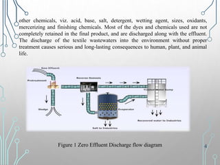
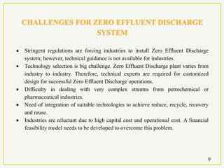
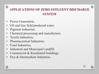
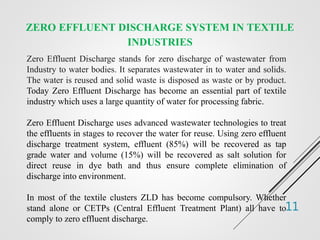
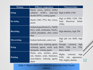
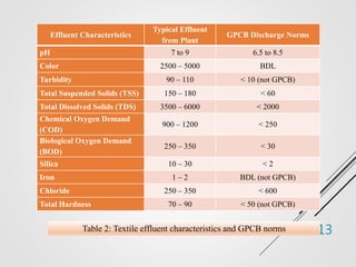
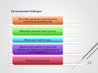
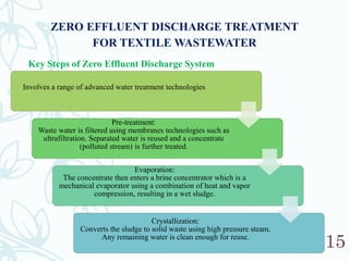
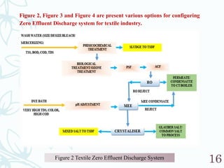
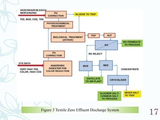
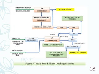
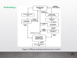
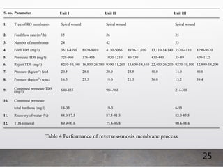
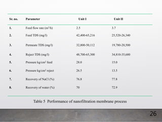
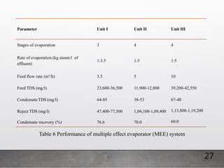
Presentation On
Zero Effluent Discharge System
Guided By:
Prof. Dr. Mehali Mehta
Prof. Ankita Parmar
Prepared By:
Desai Jhanvi Rakeshbhai (190420717002)
PG Center
Masters in Environmental (2019-2020) Engineering
GUJARAT TECHNOLOGICAL UNIVERSITY
SARVAJANIK COLLEGE OF ENGINEERING & TECHNOLOGY
Dr. R. K. Desai Marg, Athwalines, Surat – 395001
1
• Introduction
• Zero Effluent Discharge System
• Need of Zero Effluent Discharge System
• Benefits of Zero Effluent Discharge System
• Drivers of Zero Effluent Discharge System
• Challenges for Zero Effluent Discharge System
• Applications of Zero Effluent Discharge System
• Zero Effluent Discharge System In Textile Industries
• Zero Effluent Discharge Treatment for Textile Wastewater
• Case Study
• References
2
Water is fundamental to life, livelihood, food security and sustainable development;
it however is a finite resource. While most of the world’s surface is covered by
water, only about 1% is safe to drink. As our population rapidly grows, water
conservation and recycling become critical priority. Better water management is a
necessity in all industries to optimize water usage, recycle water and lower
manufacturing costs.
Water is needed in virtually every industry and manufacturing process. The
industries identified as water polluting industries are: Sugar, Distilleries, Pulp and
Paper, Tanneries, Chemicals, Dyeing and Textiles, Refineries, Food, Dairy and
Beverages, Electroplating and others. The water polluting industries discharge their
effluent having high organic contents measured in-terms of bio-chemical oxygen
demand (BOD), and other toxic constituents like metals, organic and in-organic
compounds. Zero Effluent Discharge is one system to address this challenge.
Today ZLD has become an essential part of textile industry which uses a large
quantity of water for processing fabric. The textile processing industry is not a single
entity but encompasses a range of process units, utilizing a wide variety of dyes and
INTRODUCTION
3
other chemicals, viz. acid, base, salt, detergent, wetting agent, sizes, oxidants,
mercerizing and finishing chemicals. Most of the dyes and chemicals used are not
completely retained in the final product, and are discharged along with the effluent.
The discharge of the textile wastewaters into the environment without proper
treatment causes serious and long-lasting consequences to human, plant, and animal
life.
Figure 1 Zero Effluent Discharge flow diagram 4
Zero Effluent Discharge refers to the recycling and treatment process in which the plant
discharges no liquid effluent into surface waters, completely eliminating the environmental
pollution to water bodies.
Zero Effluent Discharge refers to installation of facilities and system which enables
industrial effluent for absolute recycling of permeate and converting solute into residue in
the solid form by adopting method of concentration and thermal evaporation.
(CPCB Draft Guidelines, January, 2015.)
Zero Effluent Discharge is applicable to industries generating wastewater of high BOD/COD
load, colour, metals, pesticides, toxic/hazardous constituents, solvent and high TDS bearing
effluents. However, considering water scarcity and reject water/sludge disposal cost, many
industries are adopting Zero Effluent Discharge system as a long-term strategy.
5
NEED OF ZERO EFFLUENT DISCHARGE
SYSTEM
 Around 70% of the industrial waste is dumped into the water bodies where they
pollute the usable water supply.
 Most polluting industries such Pharma, Pulp & Paper, Textile& Dying, Tanneries,
Chemicals, Power Plant, etc. generate wastewater with high salinity/TDS.
 Conventional Physio-Chemical-Biological treatment does not remove salinity in
the treated effluent.
 For protection of environment from effluent discharge and to conserve water.
 Discharge of saline wastewater surface water further pollutes ground and surface
water resources.
 Several states in India are water stressed. Reduction in water demand from the
industry frees up water for agriculture and domestic demands.
 High cost of water and statutory regulations are prime drivers for ZLD.
 Use of Zero Effluent Discharge system and/or Water Recycling will reduce the
intake of the fresh water supply. Thus, lowering the cost, increasing the water
efficiency and minimizing the environmental impact.
 Water scarcity, water economics, regulatory pressure are the main motivators.
6
BENEFITS OF ZERO EFFLUENT DISCHARGE
SYSTEM
Handle variations in waste contamination and flow.
Natural water source utilization is reduced 90%.
Recover around 95% of liquid waste for reuse.
Recover valuable ingredients from effluent wastewater.
Salt used in the dying process is recovered and reused.
High operating costs can be justified by high recovery of water (>90-95%) and recovering of several by
products from the salt.
Zero Effluent Discharge system generally does not require a lengthy or tedious permitting process.
Reduces process water disposal cost.
It represents a positive extreme in recycling, by efficiently using the water source.
zero effluent discharge unit gain quick community acceptance.
Reduction in water demand from the industry and frees up water for agriculture and domestic demands.
No discharge of wastewater in to the environment and pollution are reduced. 7
DRIVERS OF ZERO EFFLUENT DISCHARGE
SYSTEM
Stringent environmental regulations on discharge of
specific pollutants.
Water scarcity in the area of operation.
Economics: recycled water becomes more economical
than disposal of water and buying fresh water.
Recovery of useful materials.
Growing social responsibilities towards
environmental issues.
8
CHALLENGES FOR ZERO EFFLUENT DISCHARGE
SYSTEM
 Stringent regulations are forcing industries to install Zero Effluent Discharge
system; however, technical guidance is not available for industries.
 Technology selection is big challenge. Zero Effluent Discharge plant varies from
industry to industry. Therefore, technical experts are required for customized
design for successful Zero Effluent Discharge operations.
 Difficulty in dealing with very complex streams from petrochemical or
pharmaceutical industries.
 Need of integration of suitable technologies to achieve reduce, recycle, recovery
and reuse.
 Industries are reluctant due to high capital cost and operational cost. A financial
feasibility model needs to be developed to overcome this problem.
9
APPLICATIONS OF ZERO EFFLUENT DISCHARGE
SYSTEM
10
• Power Generation.
• Oil and Gas field produced water.
• Pigment Industries.
• Chemical processing and manufacture.
• Textile Industries.
• Pharmaceutical Industries.
• Food Industries.
• Industrial and Municipal Landfill.
• Commercial & Residential buildings.
• Dye & Intermediate Industries.
11
ZERO EFFLUENT DISCHARGE SYSTEM IN TEXTILE
INDUSTRIES
Zero Effluent Discharge stands for zero discharge of wastewater from
Industry to water bodies. It separates wastewater in to water and solids.
The water is reused and solid waste is disposed as waste or by product.
Today Zero Effluent Discharge has become an essential part of textile
industry which uses a large quantity of water for processing fabric.
Zero Effluent Discharge uses advanced wastewater technologies to treat
the effluents in stages to recover the water for reuse. Using zero effluent
discharge treatment system, effluent (85%) will be recovered as tap
grade water and volume (15%) will be recovered as salt solution for
direct reuse in dye bath and thus ensure complete elimination of
discharge into environment.
In most of the textile clusters ZLD has become compulsory. Whether
stand alone or CETPs (Central Effluent Treatment Plant) all have to
comply to zero effluent discharge.
12
Process Effluent composition Characteristics
Sizing
Starch, waxes, carboxy methyl
cellulose (CMC), polyvinyl
alcohol (PVA), wetting agents.
High in BOD, COD
De-sizing
Starch, CMC, PVA, fats, waxes,
pectin
High in BOD, COD, TSS,
Total Dissolved Solids
(TDS)
Bleaching
Sodium,hypochlorite,Cl2, NaOH,
H2O2, acids, surfactants, NasiO3,
sodium phosphate, short cotton
fiber
High alkalinity, high TSS
Mercerizing Sodium hydroxide, cotton wax
High pH, low BOD, high
TDS
Dying
Dyestuffs urea, reducing agents,
oxidizing agents, acetic acid,
detergents, wetting agents
Strongly coloured, high
BOD, TDS, low TSS,
heavy metals
Printing
Pastes, urea, starches, gums,
oils, binders, acids, thickeners,
cross-linkers, reducing agents,
alkali
Highly coloured, high
COD, oily appearance,
TSS, slightly alkaline
Table 1: Major source of wastewater generation from Textile
Industry
13
Effluent Characteristics
Typical Effluent
from Plant
GPCB Discharge Norms
pH 7 to 9 6.5 to 8.5
Color 2500 – 5000 BDL
Turbidity 90 – 110 < 10 (not GPCB)
Total Suspended Solids (TSS) 150 – 180 < 60
Total Dissolved Solids (TDS) 3500 – 6000 < 2000
Chemical Oxygen Demand
(COD)
900 – 1200 < 250
Biological Oxygen Demand
(BOD)
250 – 350 < 30
Silica 10 – 30 < 2
Iron 1 – 2 BDL (not GPCB)
Chloride 250 – 350 < 600
Total Hardness 70 – 90 < 50 (not GPCB)
Table 2: Textile effluent characteristics and GPCB norms
14
Environmental challenges:
Providing appropriate pretreatment for
increasing the membrane life.
Maximize renovated water recovery.
Recovery of salt for reuse.
Minimize the quantity of rejects and
minimize the Operation & Maintenance of
reject management.
Disposal of mixed salt.
15
ZERO EFFLUENT DISCHARGE TREATMENT
FOR TEXTILE WASTEWATER
Key Steps of Zero Effluent Discharge System
Involves a range of advanced water treatment technologies
Pre-treatment:
Waste water is filtered using membranes technologies such as
ultrafiltration. Separated water is reused and a concentrate
(polluted stream) is further treated.
Evaporation:
The concentrate then enters a brine concentrator which is a
mechanical evaporator using a combination of heat and vapor
compression, resulting in a wet sludge.
Crystallization:
Converts the sludge to solid waste using high pressure steam.
Any remaining water is clean enough for reuse.
16
Figure 2 Textile Zero Effluent Discharge System
Figure 2, Figure 3 and Figure 4 are present various options for configuring
Zero Effluent Discharge system for textile industry.
17
Figure 3 Textile Zero Effluent Discharge System
18
Figure 5 Textile Zero Effluent Discharge System
19
Assessment of field scale zero liquid discharge treatment systems for recovery
of water and salt from textile effluents
Authors: G. Vishnu, S. Palanisamy, Kurian Joseph
The textile dyeing industry demands large quantities of water and produces wastewater having high load
of contaminants. The trade effluent from dyeing and bleaching units at Tirupur, India, has caused severe
environmental problems. Having understood the seriousness of the water pollution, the regulatory
agencies are insisting on treating the wastewaters to reuse it in the process itself and achieve ‘zero
discharge’. Twenty-nine large- and medium-scale dyeing units in Tirupur have installed zero discharge
treatment systems (ZDTS) consisting of different combinations of treatment technologies.
Treatment systems consisting of physico-chemical treatment, biological treatment, ozonation, reverse
osmosis system, nanofiltration system, multiple effect evaporator, crystalliser and solar evaporation
pans set up by three dyeing units in Tirupur, India, were assessed in the present study. The composite
samples were analyzed for colour, pH, TSS, TDS, chlorides, sulphates, COD, total iron, silica, SDI, LSI
and total hardness. Water recovery by reverse osmosis and salt recovery using nano filter were 87% and
71%, respectively.
20
Methodology:
Figure 6 Effluent treatment and recovery in unit I.
21
Figure 7 Effluent treatment and recovery in unit II.
22
Figure 8 Effluent treatment and recovery in unit III.
23
Result and discussion:
• Characteristics of raw effluent: The effluents were highly alkaline nature (pH range of 8.3- 12.1)
due to the addition of caustic soda in the dyeing process. The TSS in the wash water effluent of
Unit I was high (400-460 mg/l) and that of units II and III ranged from 144 mg/l to 258 mg/l. TDS
of dyebath effluent in Unit I was around 50,000 mg/l and that of in units II and III was around
30,000 mg/l. This variation is due to the difference in the machines, shades and dyes used in the
process.
• The TDS of wash water effluents of all the units were in the range of 3730 - 4520 mg/l. High TDS
is due to the usage of salt at the rate of 30-90 g/l of liquor volume in the dyeing process. The salt
used by units I and II was NaCl and that by Unit III was Na2SO4. The chlorides and sulphates in the
effluent streams are indicative of this. The concentration of chlorides in the dyebath effluent was
around 30,000 mg/l in Unit I and around 15,000 mg/l in Unit II. Sulphates were around 15,000 mg/l
in Unit III. In the washing effluent of units, I and II, chloride was around 1700 mg/l and of Unit III
it was 1100 mg/l.
• COD of the dyebath effluent from units I, II and III was around 2650 mg/l, 1360 mg/l and 850 mg/l,
respectively. COD was around 500 mg/l, 290 mg/l and 620 mg/l in the washing effluents of units I,
II and III, respectively. It was observed that the dyebath effluents were strongly coloured (34.2-
1375 m1) and washing effluents were lightly coloured (12.7-58.3 m-1).
24
Parameter Unit I Unit II Unit III
Treatment units
Equalization tank Equalization tank Equalization tank
Mixing channel Mixing channel Flash mixer and
flocculator
Primary settling Primary settling Primary clarifier
Gravity sand filter Secondary settling tank Fluidized bed bioreactor
Pressure sand filter Gravity sand filter Secondary clarifier
Activated carbon filter Multi grade filter Reactivator
Ozonation Gravity sand filter
Activated carbon filter Dual media filter
Activated carbon filter
Treated effluent qualit
Colour (m-1), 436 nm
3.1-5.9 2.7-5.3
1.3-2.1
Colour (m-1), 525 nm 2.1-4.9 0-5.8 0-1.1
Colour (m-1), 620 nm 0.4-4.5 1.5-4.7 0-0.7
COD (mg/l) 189-205 80-96 80-104
TSS (mg/l) 80-113 16-143 81-93
Table 3 Details of pre-treatment and treated effluent quality
25
S. no. Parameter Unit I Unit II Unit III
1. Type of RO membranes Spiral wound Spiral wound Spiral wound
2. Feed flow rate (m3/h) 15 26 35
3. Number of membranes 24 42 53
4. Feed TDS (mg/l) 3611-4590 8020-9910 4130-5066 8970-11,010 13,110-14,140 3570-4110 8790-9870
5. Permeate TDS (mg/l) 728-960 376-455 1020-1210 80-730 430-440 35-89 670-1125
6. Reject TDS (mg/l) 8250-10,100 16,800-26,780 9300-11,260 13,600-14,610 22,400-26,200 9270-10,100 12,840-14,200
7. Pressure (kg/cm2) feed 20.5 28.0 20.0 24.5 40.0 14.0 40.0
8. Pressure (kg/cm2) reject 16.3 25.5 19.0 21.5 36.0 13.2 39.4
9. Combined permeate TDS
(mg/l) 640-835 904-968 214-308
10. Combined permeate
total hardness (mg/l) 18-35 19-31 6-15
11. Recovery of water (%) 88.0-87.5 87.5-91.3 82.0-83.5
12. TDS removal 89.9-90.6 75.8-96.8 90.4-98.4
Table 4 Performance of reverse osmosis membrane process
26
Sr. no. Parameter Unit I Unit II
1. Feed flow rate (m3/h) 2.5 3.7
2. Feed TDS (mg/l) 42,400-65,216 25,520-26,340
3. Permeate TDS (mg/l) 32,800-50,112 19,780-20,500
4. Reject TDS (mg/l) 48,700-65,300 34,810-35,680
5. Pressure kg/cm2 feed 28.0 15.0
6. Pressure kg/cm2 reject 26.5 13.5
7. Recovery of NaCl (%) 76.8 77.8
8. Recovery of water (%) 70 72.9
Table 5 Performance of nanofiltration membrane process
27
Parameter Unit I Unit II Unit III
Stages of evaporation 3 4 4
Rate of evaporation (kg steam:l of
effluent)
1:3.5 1:5 1:5
Feed flow rate (m3/h) 3.5 5 10
Feed TDS (mg/l) 23,600-36,500 11,900-12,800 39,200-42,550
CondensateTDS (mg/l) 64-85 38-53 67-48
Reject TDS (mg/l) 47,400-77,500 1,04,100-1,09,400 1,13,800-1,19,200
Condensate recovery (%) 76.6 70.0 60.0
Table 6 Performance of multiple effect evaporator (MEE) system
28
Conclusion:
• A TDS removal efficiency of >90% resulted in permeate having average
TDS of <700 mg/l and total hardness of >20 mg/l. This coupled with the
highwater recovery of 80-90% made the RO process both technically and
economically viable for recovery and reuse of the wash water.
• The NF permeate containing 70% of the salt of the dyebath was reused
and used as dyebath water demonstrating its suitability for reuse of
dyebath effluent. The recovery of sodium chloride in solution form using
NF is more economical than recovery of sodium sulphate using MEE. The
use of NF is more economical if the feed contains higher salt
concentrations as it enhances the salt recovery and generates revenue.
• Moreover from the cost analysis it is seen that lowering the usage of
chemicals by better operation and maintenance practices would enhance
the economic feasibility of the treatment systems.
29
REFERENCES
• Best Practice – Zero Liquid Discharge (ZLD) System in Textile Processing units’ CETP in
Tamil Nadu.
• G. Vishnu, S. Palanisamy, Kurian Joseph. 2007. Assessment of fieldscale zero liquid discharge
treatment systems for recovery of water and salt from textile effluents. S.l. : Journal of cleaner
production, 2007.
• Guidelines on techno - economic feasibility of implementation of zero liquid discharge (zld) for
water polluting industries.
• Ilda Vergili, Yasemin Kaya, Unal Sen, Zeren Beril Gonder, Coskun Aydiner. 2011. Techno-
economic analysis of textile dye bath wastewater treatment by integrated membrane processes
under the zero liquid discharge approach. S.l. : Resources, Conservation and Recycling, 2011.
• Kanmani, S Priscilla Rajkumari and S. 2008. Environmental life cycle assessment of zero liquid
discharge treatment technologies for textile industry, tripur- a case study. S.l. : Journal of
scientific & Industrial research, 2008.
• Madhusudanan, P. Mani and M. 2014. Zero Liquid Discharge Scheme in a Common Effluent
Treatment Plant for Textile Industries in Tamilnadu, India. S.l. : Nature Environment and
Pollution Technology An International Quarterly Scientific Journal, 2014.
• Pankajsinh, Parmar Isha. 2018. Treatment of Secondary Effluent of Textile Industry Using RO
and Single Stage Evaporation- Approach to ZLD. S.l. : International Journal of Latest
Technology in Engineering, Management & Applied Science 2018.
• Report on assessment of pollution from textile dyeing units in tirupur, tamil nadu and measures
taken to achieve zero liquid discharge.
30
Thank You…

zero effluent discharge system

  • 1.
    Presentation On Zero EffluentDischarge System Guided By: Prof. Dr. Mehali Mehta Prof. Ankita Parmar Prepared By: Desai Jhanvi Rakeshbhai (190420717002) PG Center Masters in Environmental (2019-2020) Engineering GUJARAT TECHNOLOGICAL UNIVERSITY SARVAJANIK COLLEGE OF ENGINEERING & TECHNOLOGY Dr. R. K. Desai Marg, Athwalines, Surat – 395001 1
  • 2.
    • Introduction • ZeroEffluent Discharge System • Need of Zero Effluent Discharge System • Benefits of Zero Effluent Discharge System • Drivers of Zero Effluent Discharge System • Challenges for Zero Effluent Discharge System • Applications of Zero Effluent Discharge System • Zero Effluent Discharge System In Textile Industries • Zero Effluent Discharge Treatment for Textile Wastewater • Case Study • References 2
  • 3.
    Water is fundamentalto life, livelihood, food security and sustainable development; it however is a finite resource. While most of the world’s surface is covered by water, only about 1% is safe to drink. As our population rapidly grows, water conservation and recycling become critical priority. Better water management is a necessity in all industries to optimize water usage, recycle water and lower manufacturing costs. Water is needed in virtually every industry and manufacturing process. The industries identified as water polluting industries are: Sugar, Distilleries, Pulp and Paper, Tanneries, Chemicals, Dyeing and Textiles, Refineries, Food, Dairy and Beverages, Electroplating and others. The water polluting industries discharge their effluent having high organic contents measured in-terms of bio-chemical oxygen demand (BOD), and other toxic constituents like metals, organic and in-organic compounds. Zero Effluent Discharge is one system to address this challenge. Today ZLD has become an essential part of textile industry which uses a large quantity of water for processing fabric. The textile processing industry is not a single entity but encompasses a range of process units, utilizing a wide variety of dyes and INTRODUCTION 3
  • 4.
    other chemicals, viz.acid, base, salt, detergent, wetting agent, sizes, oxidants, mercerizing and finishing chemicals. Most of the dyes and chemicals used are not completely retained in the final product, and are discharged along with the effluent. The discharge of the textile wastewaters into the environment without proper treatment causes serious and long-lasting consequences to human, plant, and animal life. Figure 1 Zero Effluent Discharge flow diagram 4
  • 5.
    Zero Effluent Dischargerefers to the recycling and treatment process in which the plant discharges no liquid effluent into surface waters, completely eliminating the environmental pollution to water bodies. Zero Effluent Discharge refers to installation of facilities and system which enables industrial effluent for absolute recycling of permeate and converting solute into residue in the solid form by adopting method of concentration and thermal evaporation. (CPCB Draft Guidelines, January, 2015.) Zero Effluent Discharge is applicable to industries generating wastewater of high BOD/COD load, colour, metals, pesticides, toxic/hazardous constituents, solvent and high TDS bearing effluents. However, considering water scarcity and reject water/sludge disposal cost, many industries are adopting Zero Effluent Discharge system as a long-term strategy. 5
  • 6.
    NEED OF ZEROEFFLUENT DISCHARGE SYSTEM  Around 70% of the industrial waste is dumped into the water bodies where they pollute the usable water supply.  Most polluting industries such Pharma, Pulp & Paper, Textile& Dying, Tanneries, Chemicals, Power Plant, etc. generate wastewater with high salinity/TDS.  Conventional Physio-Chemical-Biological treatment does not remove salinity in the treated effluent.  For protection of environment from effluent discharge and to conserve water.  Discharge of saline wastewater surface water further pollutes ground and surface water resources.  Several states in India are water stressed. Reduction in water demand from the industry frees up water for agriculture and domestic demands.  High cost of water and statutory regulations are prime drivers for ZLD.  Use of Zero Effluent Discharge system and/or Water Recycling will reduce the intake of the fresh water supply. Thus, lowering the cost, increasing the water efficiency and minimizing the environmental impact.  Water scarcity, water economics, regulatory pressure are the main motivators. 6
  • 7.
    BENEFITS OF ZEROEFFLUENT DISCHARGE SYSTEM Handle variations in waste contamination and flow. Natural water source utilization is reduced 90%. Recover around 95% of liquid waste for reuse. Recover valuable ingredients from effluent wastewater. Salt used in the dying process is recovered and reused. High operating costs can be justified by high recovery of water (>90-95%) and recovering of several by products from the salt. Zero Effluent Discharge system generally does not require a lengthy or tedious permitting process. Reduces process water disposal cost. It represents a positive extreme in recycling, by efficiently using the water source. zero effluent discharge unit gain quick community acceptance. Reduction in water demand from the industry and frees up water for agriculture and domestic demands. No discharge of wastewater in to the environment and pollution are reduced. 7
  • 8.
    DRIVERS OF ZEROEFFLUENT DISCHARGE SYSTEM Stringent environmental regulations on discharge of specific pollutants. Water scarcity in the area of operation. Economics: recycled water becomes more economical than disposal of water and buying fresh water. Recovery of useful materials. Growing social responsibilities towards environmental issues. 8
  • 9.
    CHALLENGES FOR ZEROEFFLUENT DISCHARGE SYSTEM  Stringent regulations are forcing industries to install Zero Effluent Discharge system; however, technical guidance is not available for industries.  Technology selection is big challenge. Zero Effluent Discharge plant varies from industry to industry. Therefore, technical experts are required for customized design for successful Zero Effluent Discharge operations.  Difficulty in dealing with very complex streams from petrochemical or pharmaceutical industries.  Need of integration of suitable technologies to achieve reduce, recycle, recovery and reuse.  Industries are reluctant due to high capital cost and operational cost. A financial feasibility model needs to be developed to overcome this problem. 9
  • 10.
    APPLICATIONS OF ZEROEFFLUENT DISCHARGE SYSTEM 10 • Power Generation. • Oil and Gas field produced water. • Pigment Industries. • Chemical processing and manufacture. • Textile Industries. • Pharmaceutical Industries. • Food Industries. • Industrial and Municipal Landfill. • Commercial & Residential buildings. • Dye & Intermediate Industries.
  • 11.
    11 ZERO EFFLUENT DISCHARGESYSTEM IN TEXTILE INDUSTRIES Zero Effluent Discharge stands for zero discharge of wastewater from Industry to water bodies. It separates wastewater in to water and solids. The water is reused and solid waste is disposed as waste or by product. Today Zero Effluent Discharge has become an essential part of textile industry which uses a large quantity of water for processing fabric. Zero Effluent Discharge uses advanced wastewater technologies to treat the effluents in stages to recover the water for reuse. Using zero effluent discharge treatment system, effluent (85%) will be recovered as tap grade water and volume (15%) will be recovered as salt solution for direct reuse in dye bath and thus ensure complete elimination of discharge into environment. In most of the textile clusters ZLD has become compulsory. Whether stand alone or CETPs (Central Effluent Treatment Plant) all have to comply to zero effluent discharge.
  • 12.
    12 Process Effluent compositionCharacteristics Sizing Starch, waxes, carboxy methyl cellulose (CMC), polyvinyl alcohol (PVA), wetting agents. High in BOD, COD De-sizing Starch, CMC, PVA, fats, waxes, pectin High in BOD, COD, TSS, Total Dissolved Solids (TDS) Bleaching Sodium,hypochlorite,Cl2, NaOH, H2O2, acids, surfactants, NasiO3, sodium phosphate, short cotton fiber High alkalinity, high TSS Mercerizing Sodium hydroxide, cotton wax High pH, low BOD, high TDS Dying Dyestuffs urea, reducing agents, oxidizing agents, acetic acid, detergents, wetting agents Strongly coloured, high BOD, TDS, low TSS, heavy metals Printing Pastes, urea, starches, gums, oils, binders, acids, thickeners, cross-linkers, reducing agents, alkali Highly coloured, high COD, oily appearance, TSS, slightly alkaline Table 1: Major source of wastewater generation from Textile Industry
  • 13.
    13 Effluent Characteristics Typical Effluent fromPlant GPCB Discharge Norms pH 7 to 9 6.5 to 8.5 Color 2500 – 5000 BDL Turbidity 90 – 110 < 10 (not GPCB) Total Suspended Solids (TSS) 150 – 180 < 60 Total Dissolved Solids (TDS) 3500 – 6000 < 2000 Chemical Oxygen Demand (COD) 900 – 1200 < 250 Biological Oxygen Demand (BOD) 250 – 350 < 30 Silica 10 – 30 < 2 Iron 1 – 2 BDL (not GPCB) Chloride 250 – 350 < 600 Total Hardness 70 – 90 < 50 (not GPCB) Table 2: Textile effluent characteristics and GPCB norms
  • 14.
    14 Environmental challenges: Providing appropriatepretreatment for increasing the membrane life. Maximize renovated water recovery. Recovery of salt for reuse. Minimize the quantity of rejects and minimize the Operation & Maintenance of reject management. Disposal of mixed salt.
  • 15.
    15 ZERO EFFLUENT DISCHARGETREATMENT FOR TEXTILE WASTEWATER Key Steps of Zero Effluent Discharge System Involves a range of advanced water treatment technologies Pre-treatment: Waste water is filtered using membranes technologies such as ultrafiltration. Separated water is reused and a concentrate (polluted stream) is further treated. Evaporation: The concentrate then enters a brine concentrator which is a mechanical evaporator using a combination of heat and vapor compression, resulting in a wet sludge. Crystallization: Converts the sludge to solid waste using high pressure steam. Any remaining water is clean enough for reuse.
  • 16.
    16 Figure 2 TextileZero Effluent Discharge System Figure 2, Figure 3 and Figure 4 are present various options for configuring Zero Effluent Discharge system for textile industry.
  • 17.
    17 Figure 3 TextileZero Effluent Discharge System
  • 18.
    18 Figure 5 TextileZero Effluent Discharge System
  • 19.
    19 Assessment of fieldscale zero liquid discharge treatment systems for recovery of water and salt from textile effluents Authors: G. Vishnu, S. Palanisamy, Kurian Joseph The textile dyeing industry demands large quantities of water and produces wastewater having high load of contaminants. The trade effluent from dyeing and bleaching units at Tirupur, India, has caused severe environmental problems. Having understood the seriousness of the water pollution, the regulatory agencies are insisting on treating the wastewaters to reuse it in the process itself and achieve ‘zero discharge’. Twenty-nine large- and medium-scale dyeing units in Tirupur have installed zero discharge treatment systems (ZDTS) consisting of different combinations of treatment technologies. Treatment systems consisting of physico-chemical treatment, biological treatment, ozonation, reverse osmosis system, nanofiltration system, multiple effect evaporator, crystalliser and solar evaporation pans set up by three dyeing units in Tirupur, India, were assessed in the present study. The composite samples were analyzed for colour, pH, TSS, TDS, chlorides, sulphates, COD, total iron, silica, SDI, LSI and total hardness. Water recovery by reverse osmosis and salt recovery using nano filter were 87% and 71%, respectively.
  • 20.
    20 Methodology: Figure 6 Effluenttreatment and recovery in unit I.
  • 21.
    21 Figure 7 Effluenttreatment and recovery in unit II.
  • 22.
    22 Figure 8 Effluenttreatment and recovery in unit III.
  • 23.
    23 Result and discussion: •Characteristics of raw effluent: The effluents were highly alkaline nature (pH range of 8.3- 12.1) due to the addition of caustic soda in the dyeing process. The TSS in the wash water effluent of Unit I was high (400-460 mg/l) and that of units II and III ranged from 144 mg/l to 258 mg/l. TDS of dyebath effluent in Unit I was around 50,000 mg/l and that of in units II and III was around 30,000 mg/l. This variation is due to the difference in the machines, shades and dyes used in the process. • The TDS of wash water effluents of all the units were in the range of 3730 - 4520 mg/l. High TDS is due to the usage of salt at the rate of 30-90 g/l of liquor volume in the dyeing process. The salt used by units I and II was NaCl and that by Unit III was Na2SO4. The chlorides and sulphates in the effluent streams are indicative of this. The concentration of chlorides in the dyebath effluent was around 30,000 mg/l in Unit I and around 15,000 mg/l in Unit II. Sulphates were around 15,000 mg/l in Unit III. In the washing effluent of units, I and II, chloride was around 1700 mg/l and of Unit III it was 1100 mg/l. • COD of the dyebath effluent from units I, II and III was around 2650 mg/l, 1360 mg/l and 850 mg/l, respectively. COD was around 500 mg/l, 290 mg/l and 620 mg/l in the washing effluents of units I, II and III, respectively. It was observed that the dyebath effluents were strongly coloured (34.2- 1375 m1) and washing effluents were lightly coloured (12.7-58.3 m-1).
  • 24.
    24 Parameter Unit IUnit II Unit III Treatment units Equalization tank Equalization tank Equalization tank Mixing channel Mixing channel Flash mixer and flocculator Primary settling Primary settling Primary clarifier Gravity sand filter Secondary settling tank Fluidized bed bioreactor Pressure sand filter Gravity sand filter Secondary clarifier Activated carbon filter Multi grade filter Reactivator Ozonation Gravity sand filter Activated carbon filter Dual media filter Activated carbon filter Treated effluent qualit Colour (m-1), 436 nm 3.1-5.9 2.7-5.3 1.3-2.1 Colour (m-1), 525 nm 2.1-4.9 0-5.8 0-1.1 Colour (m-1), 620 nm 0.4-4.5 1.5-4.7 0-0.7 COD (mg/l) 189-205 80-96 80-104 TSS (mg/l) 80-113 16-143 81-93 Table 3 Details of pre-treatment and treated effluent quality
  • 25.
    25 S. no. ParameterUnit I Unit II Unit III 1. Type of RO membranes Spiral wound Spiral wound Spiral wound 2. Feed flow rate (m3/h) 15 26 35 3. Number of membranes 24 42 53 4. Feed TDS (mg/l) 3611-4590 8020-9910 4130-5066 8970-11,010 13,110-14,140 3570-4110 8790-9870 5. Permeate TDS (mg/l) 728-960 376-455 1020-1210 80-730 430-440 35-89 670-1125 6. Reject TDS (mg/l) 8250-10,100 16,800-26,780 9300-11,260 13,600-14,610 22,400-26,200 9270-10,100 12,840-14,200 7. Pressure (kg/cm2) feed 20.5 28.0 20.0 24.5 40.0 14.0 40.0 8. Pressure (kg/cm2) reject 16.3 25.5 19.0 21.5 36.0 13.2 39.4 9. Combined permeate TDS (mg/l) 640-835 904-968 214-308 10. Combined permeate total hardness (mg/l) 18-35 19-31 6-15 11. Recovery of water (%) 88.0-87.5 87.5-91.3 82.0-83.5 12. TDS removal 89.9-90.6 75.8-96.8 90.4-98.4 Table 4 Performance of reverse osmosis membrane process
  • 26.
    26 Sr. no. ParameterUnit I Unit II 1. Feed flow rate (m3/h) 2.5 3.7 2. Feed TDS (mg/l) 42,400-65,216 25,520-26,340 3. Permeate TDS (mg/l) 32,800-50,112 19,780-20,500 4. Reject TDS (mg/l) 48,700-65,300 34,810-35,680 5. Pressure kg/cm2 feed 28.0 15.0 6. Pressure kg/cm2 reject 26.5 13.5 7. Recovery of NaCl (%) 76.8 77.8 8. Recovery of water (%) 70 72.9 Table 5 Performance of nanofiltration membrane process
  • 27.
    27 Parameter Unit IUnit II Unit III Stages of evaporation 3 4 4 Rate of evaporation (kg steam:l of effluent) 1:3.5 1:5 1:5 Feed flow rate (m3/h) 3.5 5 10 Feed TDS (mg/l) 23,600-36,500 11,900-12,800 39,200-42,550 CondensateTDS (mg/l) 64-85 38-53 67-48 Reject TDS (mg/l) 47,400-77,500 1,04,100-1,09,400 1,13,800-1,19,200 Condensate recovery (%) 76.6 70.0 60.0 Table 6 Performance of multiple effect evaporator (MEE) system
  • 28.
    28 Conclusion: • A TDSremoval efficiency of >90% resulted in permeate having average TDS of <700 mg/l and total hardness of >20 mg/l. This coupled with the highwater recovery of 80-90% made the RO process both technically and economically viable for recovery and reuse of the wash water. • The NF permeate containing 70% of the salt of the dyebath was reused and used as dyebath water demonstrating its suitability for reuse of dyebath effluent. The recovery of sodium chloride in solution form using NF is more economical than recovery of sodium sulphate using MEE. The use of NF is more economical if the feed contains higher salt concentrations as it enhances the salt recovery and generates revenue. • Moreover from the cost analysis it is seen that lowering the usage of chemicals by better operation and maintenance practices would enhance the economic feasibility of the treatment systems.
  • 29.
    29 REFERENCES • Best Practice– Zero Liquid Discharge (ZLD) System in Textile Processing units’ CETP in Tamil Nadu. • G. Vishnu, S. Palanisamy, Kurian Joseph. 2007. Assessment of fieldscale zero liquid discharge treatment systems for recovery of water and salt from textile effluents. S.l. : Journal of cleaner production, 2007. • Guidelines on techno - economic feasibility of implementation of zero liquid discharge (zld) for water polluting industries. • Ilda Vergili, Yasemin Kaya, Unal Sen, Zeren Beril Gonder, Coskun Aydiner. 2011. Techno- economic analysis of textile dye bath wastewater treatment by integrated membrane processes under the zero liquid discharge approach. S.l. : Resources, Conservation and Recycling, 2011. • Kanmani, S Priscilla Rajkumari and S. 2008. Environmental life cycle assessment of zero liquid discharge treatment technologies for textile industry, tripur- a case study. S.l. : Journal of scientific & Industrial research, 2008. • Madhusudanan, P. Mani and M. 2014. Zero Liquid Discharge Scheme in a Common Effluent Treatment Plant for Textile Industries in Tamilnadu, India. S.l. : Nature Environment and Pollution Technology An International Quarterly Scientific Journal, 2014. • Pankajsinh, Parmar Isha. 2018. Treatment of Secondary Effluent of Textile Industry Using RO and Single Stage Evaporation- Approach to ZLD. S.l. : International Journal of Latest Technology in Engineering, Management & Applied Science 2018. • Report on assessment of pollution from textile dyeing units in tirupur, tamil nadu and measures taken to achieve zero liquid discharge.
  • 30.