This document contains a 35-page exam on electrical circuit analysis techniques including nodal analysis, mesh analysis, Thevenin's theorem, Norton's theorem, and maximum power transfer theorem. It includes 37 practice problems of varying difficulty, asking students to use these analysis methods to solve circuits, determine equivalent circuits, calculate voltages, currents, power, and efficiency. The document provides circuit diagrams, explanations of analysis steps, and spaces for students to show their work and solutions.


![Page5of35(AZ)
8.2) Find the voltages at the three nonreference nodes in the circuit of Fig. 3.6. [ v1=32 V, v2=25.6 V, v3=
62.4V ]
Fig.3.6
Answer: [Try to solve it]](https://image.slidesharecdn.com/3oaryf9q8ax5rjjuzxax-signature-57131695d886dc7a3b4649a55fe4a467c7ec7cae92d186c688b947f51b4408af-poli-170524023511/85/EEE-2-5-320.jpg)
![Page6of35(AZ)
9.2) For the circuit shown in Fig, find the node voltages.
Answer: [Try to solve]
10.2) For the circuit shown in Fig. 3.9, find the node voltages.
Fig.3.9
Solution:
3.10(a)](https://image.slidesharecdn.com/3oaryf9q8ax5rjjuzxax-signature-57131695d886dc7a3b4649a55fe4a467c7ec7cae92d186c688b947f51b4408af-poli-170524023511/85/EEE-2-6-320.jpg)

![Page8of35(AZ)
11.2) Find v and i in the circuit of Figure. [Answer: - 400 mV, 2.8 A]
Solution: [Try to solve]
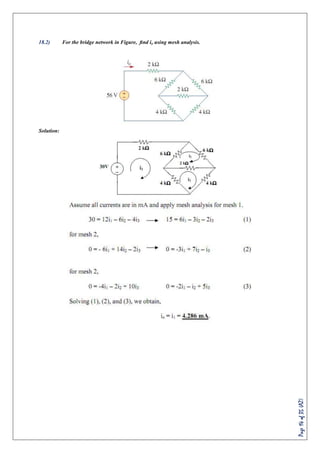
12.2) Use mesh analysis to determine and in Fig. 3.25. [ Answer: i1=4.632 A, i2= 631.6 mA, i3=1.4736 A.]
Fig.3.25
Solution: [Try to solve]](https://image.slidesharecdn.com/3oaryf9q8ax5rjjuzxax-signature-57131695d886dc7a3b4649a55fe4a467c7ec7cae92d186c688b947f51b4408af-poli-170524023511/85/EEE-2-8-320.jpg)

![Page10of35(AZ)
14.2) Calculate the mesh currents I1 and I2 of the circuit of Fig. 3.19. [I1=2.5A, I2=0]
Fig.3.19
Solution: [Try to solve]
15.2) Use mesh analysis to find the current Io in the circuit of Fig. 3.20.
Fig.3.20](https://image.slidesharecdn.com/3oaryf9q8ax5rjjuzxax-signature-57131695d886dc7a3b4649a55fe4a467c7ec7cae92d186c688b947f51b4408af-poli-170524023511/85/EEE-2-10-320.jpg)

![Page12of35(AZ)
16.2) Using mesh analysis, find Io in the circuit of Figure. [Answer: -4A]
Solution: [Try to solve]](https://image.slidesharecdn.com/3oaryf9q8ax5rjjuzxax-signature-57131695d886dc7a3b4649a55fe4a467c7ec7cae92d186c688b947f51b4408af-poli-170524023511/85/EEE-2-12-320.jpg)


![Page16of35(AZ)
20.2) Find vx and ix in the circuit shown in Fig.
Solution:
21.2) Determine current in 5Ω resistor by any one method. [Answer: 3.633A ]
Solution: [Try to solve]](https://image.slidesharecdn.com/3oaryf9q8ax5rjjuzxax-signature-57131695d886dc7a3b4649a55fe4a467c7ec7cae92d186c688b947f51b4408af-poli-170524023511/85/EEE-2-16-320.jpg)

![Page18of35(AZ)
23.2) Use nodal analysis to determine the voltage across 5Ω resistance and the current in the 12V
source. [Answer: 14.18 volt, 1.412 amp ]
Solution: [Try to solve]
24.2) Use the superposition theorem to find v in the circuit of Fig. 4.6.
Fig.4.6
Solution:](https://image.slidesharecdn.com/3oaryf9q8ax5rjjuzxax-signature-57131695d886dc7a3b4649a55fe4a467c7ec7cae92d186c688b947f51b4408af-poli-170524023511/85/EEE-2-18-320.jpg)


![Page21of35(AZ)
26.2) Find I in the circuit of Fig. 4.14 using the superposition principle. [Answer: 375 mA]](https://image.slidesharecdn.com/3oaryf9q8ax5rjjuzxax-signature-57131695d886dc7a3b4649a55fe4a467c7ec7cae92d186c688b947f51b4408af-poli-170524023511/85/EEE-2-21-320.jpg)


![Page25of35(AZ)
29.2) Find io in the circuit using source transformation. [Answer: 1.78 A.]
30.2) Find the Thevenin equivalent circuit of the circuit shown in Fig. 4.27, to the left of the terminals a-
b Then find the current through RL= 6, 16 and 36 Ohm.
Fig.4.27
Solution:](https://image.slidesharecdn.com/3oaryf9q8ax5rjjuzxax-signature-57131695d886dc7a3b4649a55fe4a467c7ec7cae92d186c688b947f51b4408af-poli-170524023511/85/EEE-2-25-320.jpg)


