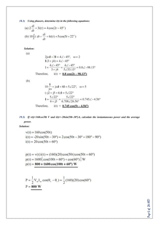
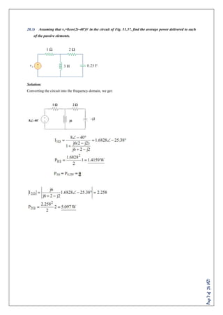
This document contains a set of practice problems related to sinusoidal signals, phasors, and AC power analysis. It begins with definitions of terms like sinusoids, phasors, resistance, inductance, capacitance, and impedance. It then presents 35 problems involving concepts like phasor representations of signals, phase relationships between voltage and current in different circuit elements, power calculations, RMS values, and power factors. The document spans 24 pages and provides the questions, blank spaces for solutions, and sometimes diagrams related to circuit analysis.


![Page16of24(AZ)
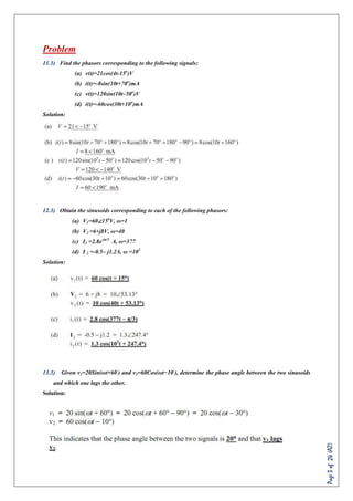
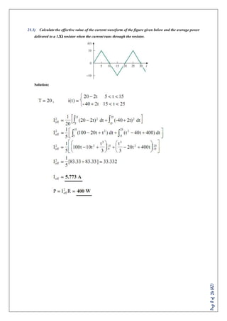
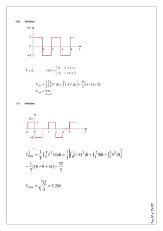
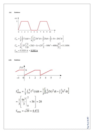
24.3) Find the rms value of the current waveform of Fig. 11.15. If the current flows through a resistor,
calculate the average power absorbed by the resistor. [Answer: 9.238 A, 768 W]
Solution:](https://image.slidesharecdn.com/b8ices46r9evf1cjtmxl-signature-57131695d886dc7a3b4649a55fe4a467c7ec7cae92d186c688b947f51b4408af-poli-170524023512/85/EEE-3-16-320.jpg)
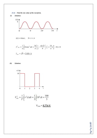
![Page18of24(AZ)
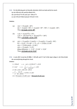
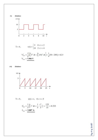
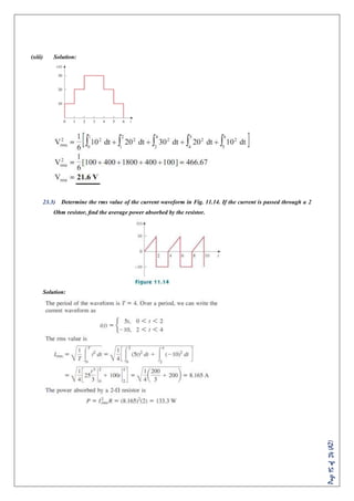
26.3) Find the rms value of the full-wave rectified sine wave in Fig. 11.17. Calculate the average power
dissipated in a resistor. [Answer: 70.71V, 833.3W]
Solution:
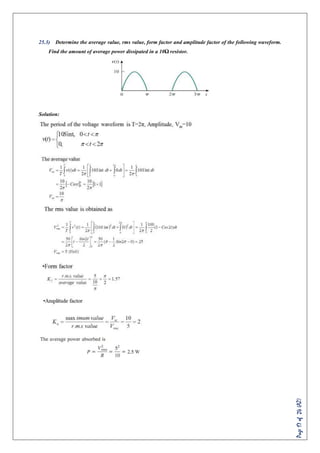
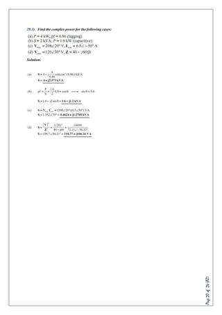
27.3) A 110-V rms, 60Hz source is applied to a load impedance Z. The apparent power entering the load is
120VA at a power factor of 0.707 lagging.
(a) Calculate the complex power.
(b) Find the rms current supplied to the load.
(c) Determine Z.
(d) Assuming that Z = R + jωL, find the values of R and L.
Solution:](https://image.slidesharecdn.com/b8ices46r9evf1cjtmxl-signature-57131695d886dc7a3b4649a55fe4a467c7ec7cae92d186c688b947f51b4408af-poli-170524023512/85/EEE-3-18-320.jpg)


![Trigonometry [QEE-R 2012]](https://cdn.slidesharecdn.com/ss_thumbnails/qeereviewproblemswithsoln-120412063344-phpapp02-thumbnail.jpg?width=640&height=640&fit=bounds)


![AC_CIRCUITS[1].pptx](https://cdn.slidesharecdn.com/ss_thumbnails/accircuits1-230813170350-dc7f310b-thumbnail.jpg?width=640&height=640&fit=bounds)


