Introduction to ElectricalMachine (ECEG 3141)
Chapter One
Magnetic Circuits and Magnetic Materials
SECE, DDIT 2024/25 By Muluhabt D.
2.
Outlines
Basic lawsof magnetic theory,
Magnetic circuit analysis,
Flux linkage,
Inductance and Energy,
Properties of magnetic materials,
AC excitation,
Permanent Magnets,
Magnetic Core Losses.
3.
1.1. Introduction
BasicLaws of Magnetic Theory
Magnetic theory studies how electric charges and currents interact, forming the basis of
electromagnetic forces and waves.
Electromagnetic theory is based on four fundamental equations, known as Maxwell’s
equations, that relate electric and magnetic fields to their sources and to each other.
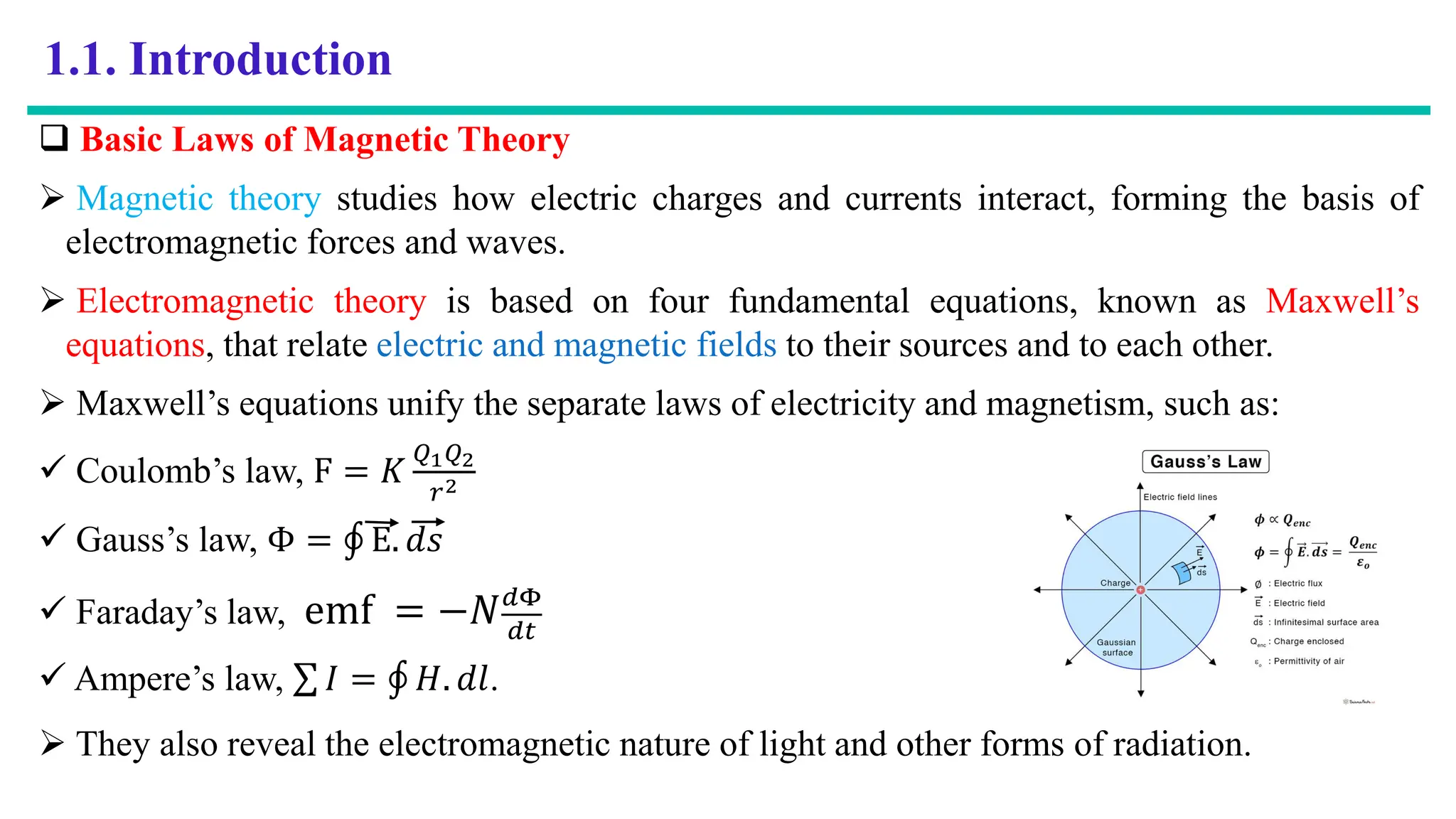
Maxwell’s equations unify the separate laws of electricity and magnetism, such as:
Coulomb’s law, F = 𝐾
𝑄1𝑄2
𝑟2
Gauss’s law, Φ = ׯ E. 𝑑𝑠
Faraday’s law, emf = −𝑁𝑑Φ
𝑑𝑡
Ampere’s law, σ 𝐼 = ׯ 𝐻. 𝑑𝑙.
They also reveal the electromagnetic nature of light and other forms of radiation.
4.
Cont…
Magnetic CircuitAnalysis
A magnetic circuit is a path that magnetic flux follows, and it is a fundamental concept in
the study of electromagnetism.
In the same way that electric circuits are essential in the design and analysis of electronic
devices, magnetic circuits play a crucial role in the construction and performance of
magnetic devices.
Magnetic circuits are essential in the design of motors, transformers, and generators.
The basic components include a magnetic material, a magnetic source such as a magnet or
an electric current, and a magnetic field.
The magnetic field is produced by the magnetic source, and it travels through the magnetic
material along the magnetic circuit.
The magnetic material is chosen based on its magnetic properties, and it is often a material
with high magnetic permeability.
5.
Cont…
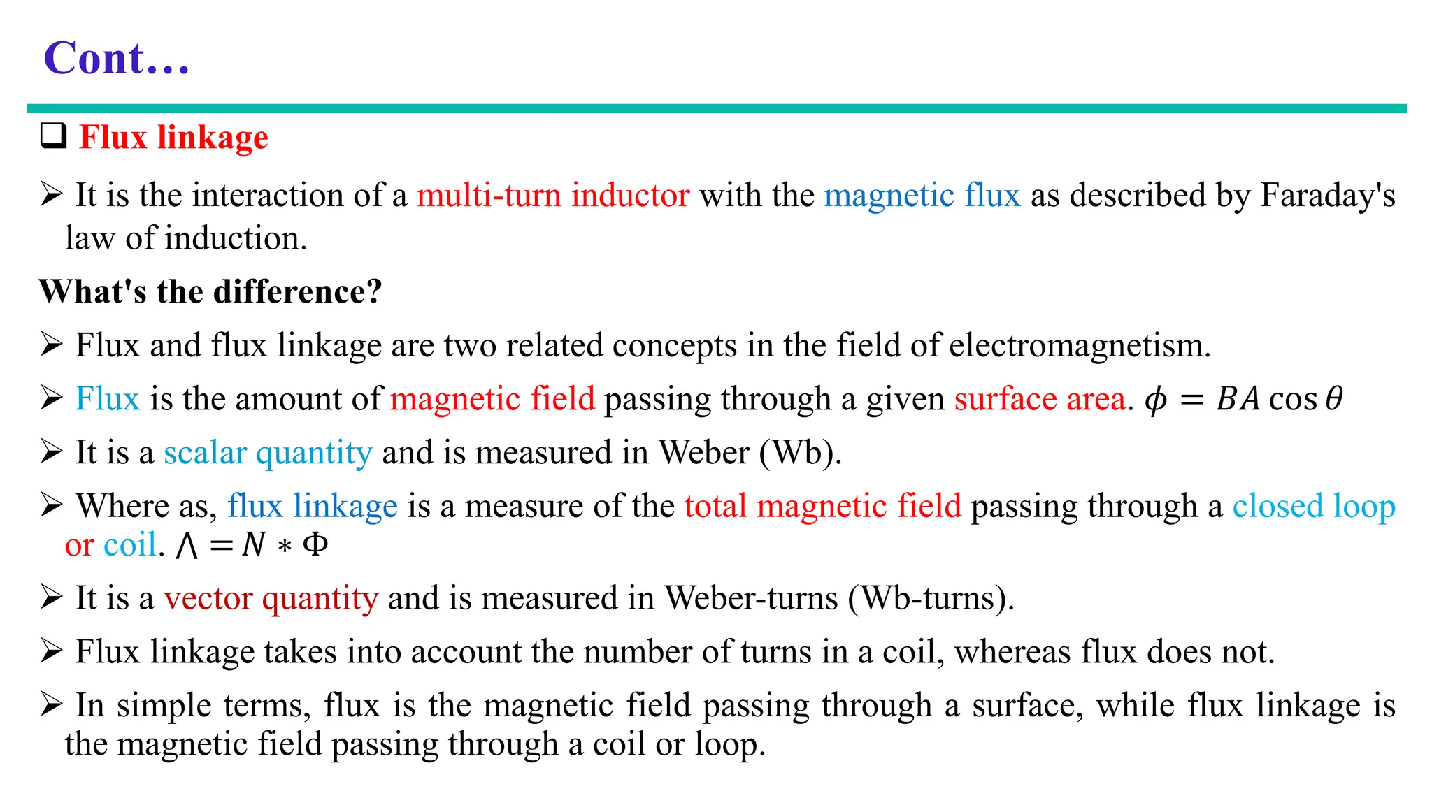
Flux linkage
It is the interaction of a multi-turn inductor with the magnetic flux as described by Faraday's
law of induction.
What's the difference?
Flux and flux linkage are two related concepts in the field of electromagnetism.
Flux is the amount of magnetic field passing through a given surface area. 𝜙 = 𝐵𝐴 cos 𝜃
It is a scalar quantity and is measured in Weber (Wb).
Where as, flux linkage is a measure of the total magnetic field passing through a closed loop
or coil. ٿ = 𝑁 ∗ Φ
It is a vector quantity and is measured in Weber-turns (Wb-turns).
Flux linkage takes into account the number of turns in a coil, whereas flux does not.
In simple terms, flux is the magnetic field passing through a surface, while flux linkage is
the magnetic field passing through a coil or loop.
6.
Cont…
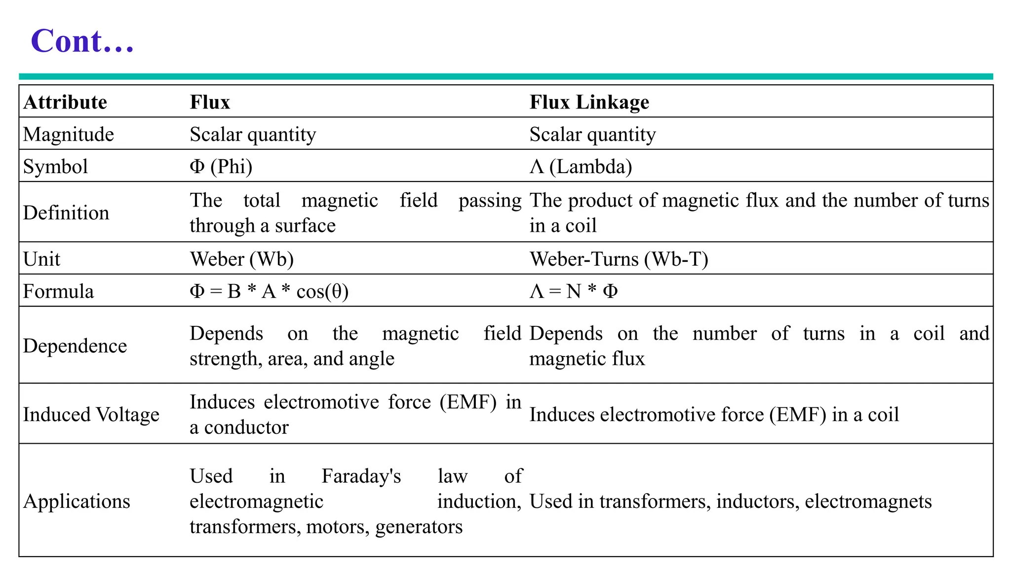
Attribute Flux FluxLinkage
Magnitude Scalar quantity Scalar quantity
Symbol Φ (Phi) Λ (Lambda)
Definition
The total magnetic field passing
through a surface
The product of magnetic flux and the number of turns
in a coil
Unit Weber (Wb) Weber-Turns (Wb-T)
Formula Φ = B * A * cos(θ) Λ = N * Φ
Dependence
Depends on the magnetic field
strength, area, and angle
Depends on the number of turns in a coil and
magnetic flux
Induced Voltage
Induces electromotive force (EMF) in
a conductor
Induces electromotive force (EMF) in a coil
Applications
Used in Faraday's law of
electromagnetic induction,
transformers, motors, generators
Used in transformers, inductors, electromagnets
7.
Cont…
Inductance andEnergy
Inductance: is the ability of an inductor to store energy in a magnetic field.
The energy is stored in the field as the current through the inductor changes, creating a
voltage drop across the inductor.
The energy stored in the field is proportional to the square of the current and the inductance
of the inductor.
Properties of Magnetic Material
It feels a force from a magnetic field and can attract or repeal other magnetic materials.
It has two magnetic poles, north and south that always exist in pairs.
It aligns itself the north-south direction when suspended freely in mid-air.
It can be classified in to three groups: diamagnetic, paramagnetic and ferromagnetic
depending on how it responds to an external magnetic filed.
8.
Cont…
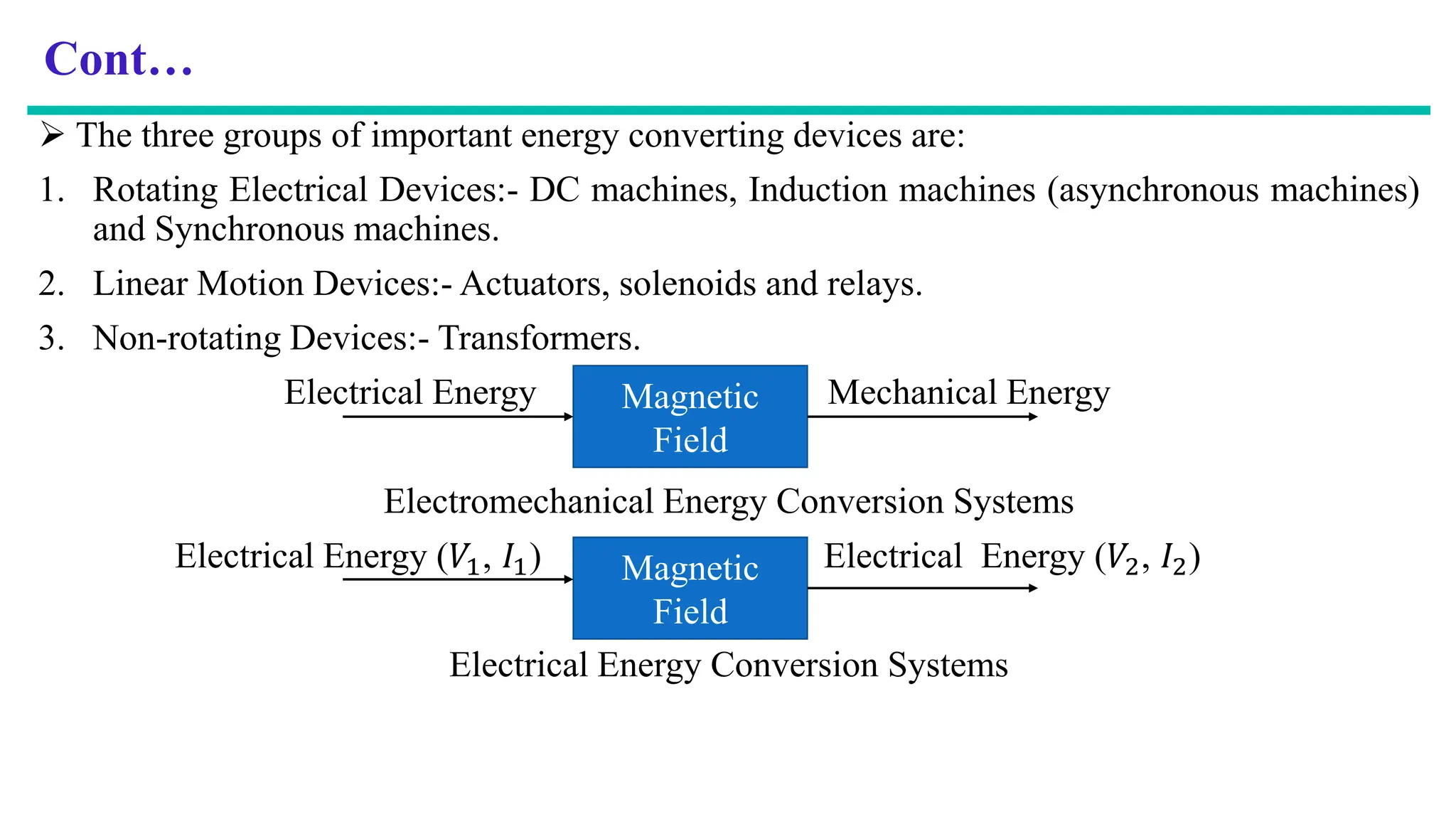
The threegroups of important energy converting devices are:
1. Rotating Electrical Devices:- DC machines, Induction machines (asynchronous machines)
and Synchronous machines.
2. Linear Motion Devices:- Actuators, solenoids and relays.
3. Non-rotating Devices:- Transformers.
Electrical Energy Mechanical Energy
Electromechanical Energy Conversion Systems
Electrical Energy (𝑉1, 𝐼1) Electrical Energy (𝑉2, 𝐼2)
Electrical Energy Conversion Systems
Magnetic
Field
Magnetic
Field
9.
Cont…
The threeaspects to establish the magnetic circuit or the magnetic field.
These are:
a. Producing the magnetic field-use coils and current (permanent magnet),
b. Magnetic field medium-use magnetic material as medium,
c. Shaping the magnetic material-a structure to shape and direct magnetic field.
Magnetic circuit is important b/s it is responsible for conversion of energy. It is formed by:
coils and current (permanent magnet),
magnetic material in conjunction with an air medium or magnetic material only.
10.
Cont…
Rotating electricalmachines such as:-
DC machines,
Induction Machines (Asynchronous Machines), perform energy conversion system.
Synchronous machines.
Electromechanical energy conversion system is the process of converting electrical energy
into mechanical energy or vice versa.
Actuators, solenoids and relays are concerned with linear motion.
Magnetic materials with magnetic circuits are used to:
shape and magnetic fields.
direct
Magnetic fields act as medium in electromechanical energy conversion system.
Major advantages of using magnetic materials is to obtain high flux density.
High flux density results in large torque or large machine output per unit machine volume.
11.
Cont….
The sizeof machine is greatly reduced by the use of magnetic materials.
Magnetic materials form a major part in the construction of electrical machines.
Magnetic circuits may be formed by ferromagnetic materials (only in transformers) or by
ferromagnetic materials in conjunction with an air medium in rotating machines.
In most electrical machines, except permanent magnet machines, the magnetic field (flux) is
produced by passing an electrical current through coils wound on ferromagnetic materials.
A. i-H Relation
The direction of flux lines or magnetic field intensity H determined by thumb rule, which
states that if the conductor is held with the right hand with the thumb indicating the direction
of current in the conductor, then the fingertips indicate the direction of magnetic field
intensity.
Ampere’s Law; states that the line integral of magnetic field intensity H around a closed
path is equal to the total current linked the contour.
12.
Cont….
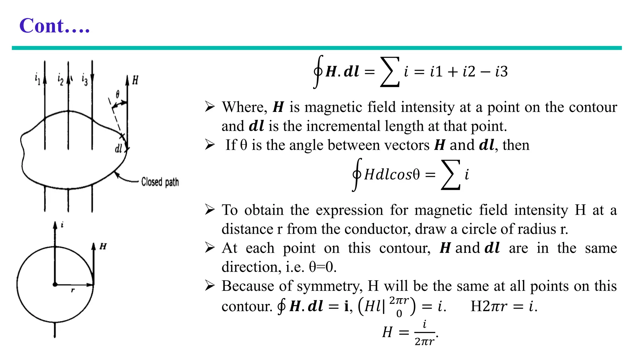
ර𝑯. 𝒅𝒍 = 𝑖 = 𝑖1 + 𝑖2 − 𝑖3
Where, 𝑯 is magnetic field intensity at a point on the contour
and 𝒅𝒍 is the incremental length at that point.
If θ is the angle between vectors 𝑯 and 𝒅𝒍, then
ර𝐻𝑑𝑙𝑐𝑜𝑠θ = 𝑖
To obtain the expression for magnetic field intensity H at a
distance r from the conductor, draw a circle of radius r.
At each point on this contour, 𝑯 and 𝒅𝒍 are in the same
direction, i.e. θ=0.
Because of symmetry, H will be the same at all points on this
contour. ׯ 𝑯. 𝒅𝒍 = 𝐢, ȁ
𝐻𝑙 2𝜋𝑟
0
= 𝑖. H2𝜋𝑟 = 𝑖.
𝐻 =
𝑖
2𝜋𝑟
.
13.
Cont….
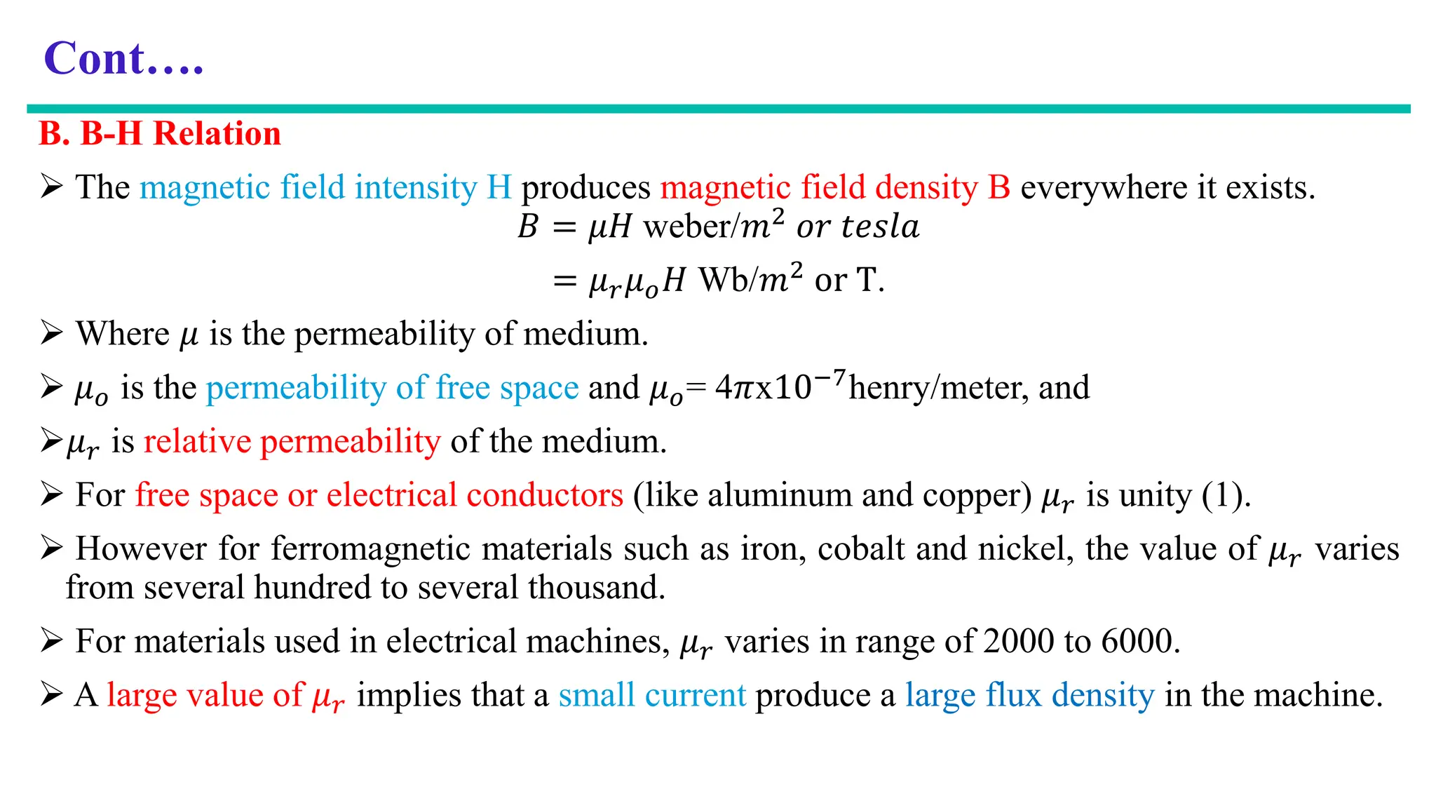
B. B-H Relation
The magnetic field intensity H produces magnetic field density B everywhere it exists.
𝐵 = 𝜇𝐻 weber/𝑚2 𝑜𝑟 𝑡𝑒𝑠𝑙𝑎
= 𝜇𝑟𝜇𝑜𝐻 Wb/𝑚2 or T.
Where 𝜇 is the permeability of medium.
𝜇𝑜 is the permeability of free space and 𝜇𝑜= 4𝜋x10−7henry/meter, and
𝜇𝑟 is relative permeability of the medium.
For free space or electrical conductors (like aluminum and copper) 𝜇𝑟 is unity (1).
However for ferromagnetic materials such as iron, cobalt and nickel, the value of 𝜇𝑟 varies
from several hundred to several thousand.
For materials used in electrical machines, 𝜇𝑟 varies in range of 2000 to 6000.
A large value of 𝜇𝑟 implies that a small current produce a large flux density in the machine.
14.
Cont….
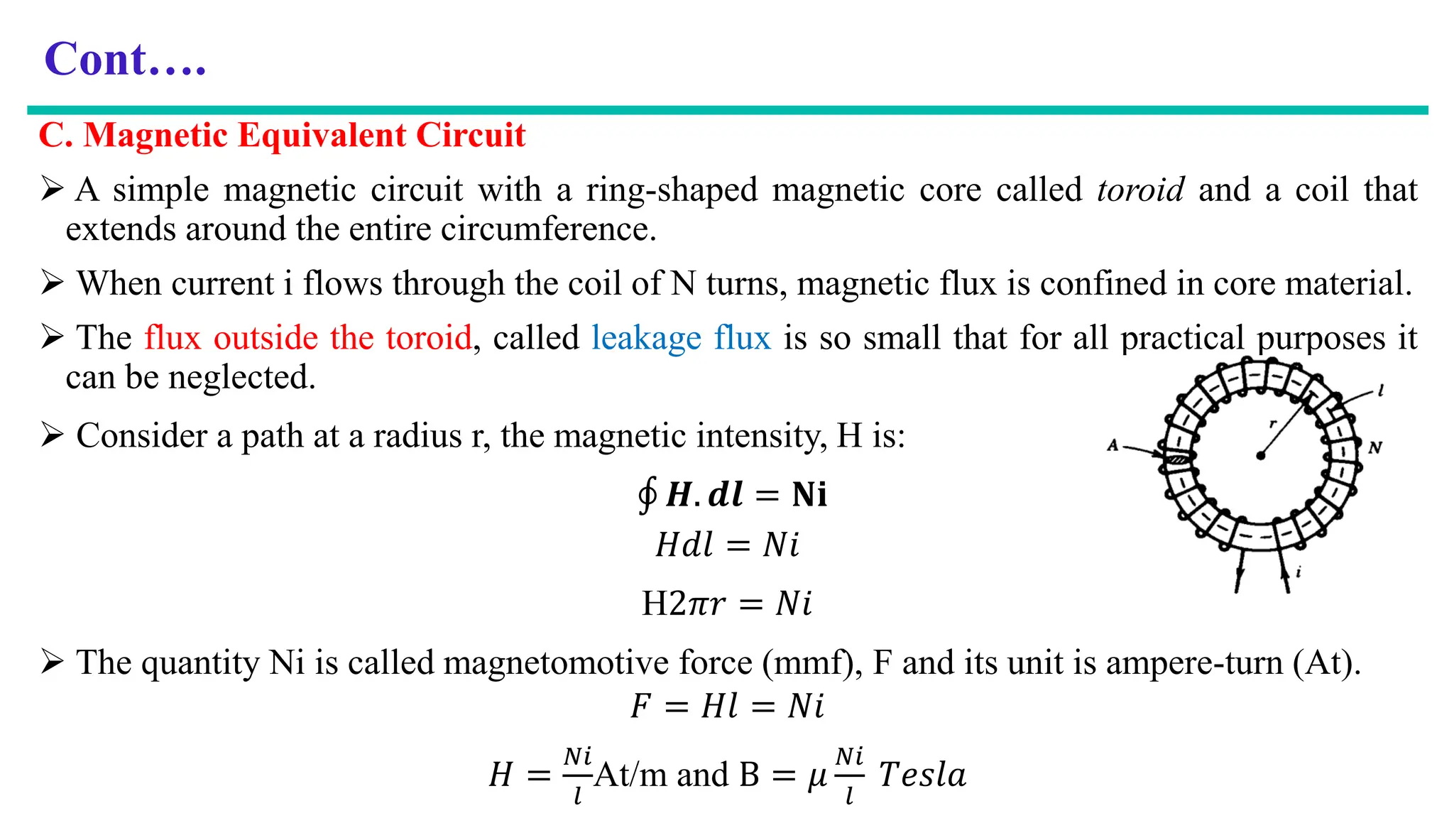
C. Magnetic EquivalentCircuit
A simple magnetic circuit with a ring-shaped magnetic core called toroid and a coil that
extends around the entire circumference.
When current i flows through the coil of N turns, magnetic flux is confined in core material.
The flux outside the toroid, called leakage flux is so small that for all practical purposes it
can be neglected.
Consider a path at a radius r, the magnetic intensity, H is:
ׯ 𝑯. 𝒅𝒍 = 𝐍𝐢
𝐻𝑑𝑙 = 𝑁𝑖
H2𝜋𝑟 = 𝑁𝑖
The quantity Ni is called magnetomotive force (mmf), F and its unit is ampere-turn (At).
𝐹 = 𝐻𝑙 = 𝑁𝑖
𝐻 =
𝑁𝑖
𝑙
At/m and B = 𝜇
𝑁𝑖
𝑙
𝑇𝑒𝑠𝑙𝑎
15.
Cont….
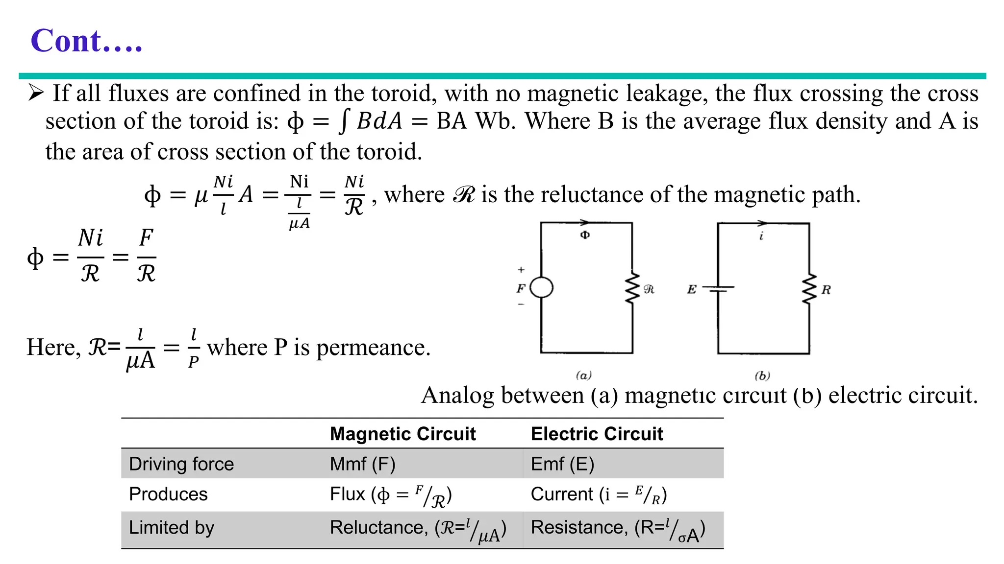
If allfluxes are confined in the toroid, with no magnetic leakage, the flux crossing the cross
section of the toroid is: ɸ = 𝐵𝑑𝐴 = BA Wb. Where B is the average flux density and A is
the area of cross section of the toroid.
ɸ = 𝜇
𝑁𝑖
𝑙
𝐴 =
Ni
𝑙
𝜇𝐴
=
𝑁𝑖
ℛ
, where ℛ is the reluctance of the magnetic path.
ɸ =
𝑁𝑖
ℛ
=
𝐹
ℛ
Here, ℛ=
𝑙
𝜇A
=
𝑙
𝑃
where P is permeance.
Analog between (a) magnetic circuit (b) electric circuit.
Magnetic Circuit Electric Circuit
Driving force Mmf (F) Emf (E)
Produces Flux (ɸ = ൗ
𝐹
ℛ) Current (i = Τ
𝐸
𝑅)
Limited by Reluctance, (ℛ= ൗ
𝑙
𝜇A) Resistance, (R= ൗ
𝑙
σA)
16.
Cont….
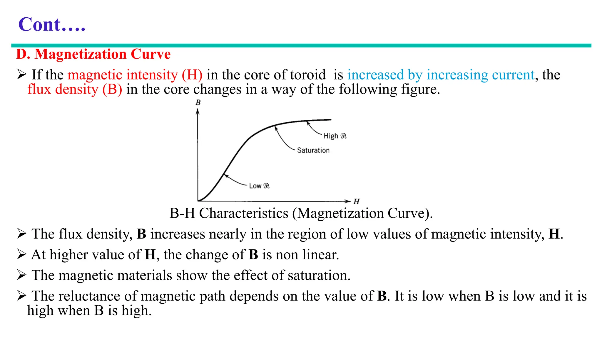
D. Magnetization Curve
If the magnetic intensity (H) in the core of toroid is increased by increasing current, the
flux density (B) in the core changes in a way of the following figure.
B-H Characteristics (Magnetization Curve).
The flux density, B increases nearly in the region of low values of magnetic intensity, H.
At higher value of H, the change of B is non linear.
The magnetic materials show the effect of saturation.
The reluctance of magnetic path depends on the value of B. It is low when B is low and it is
high when B is high.
17.
Cont….
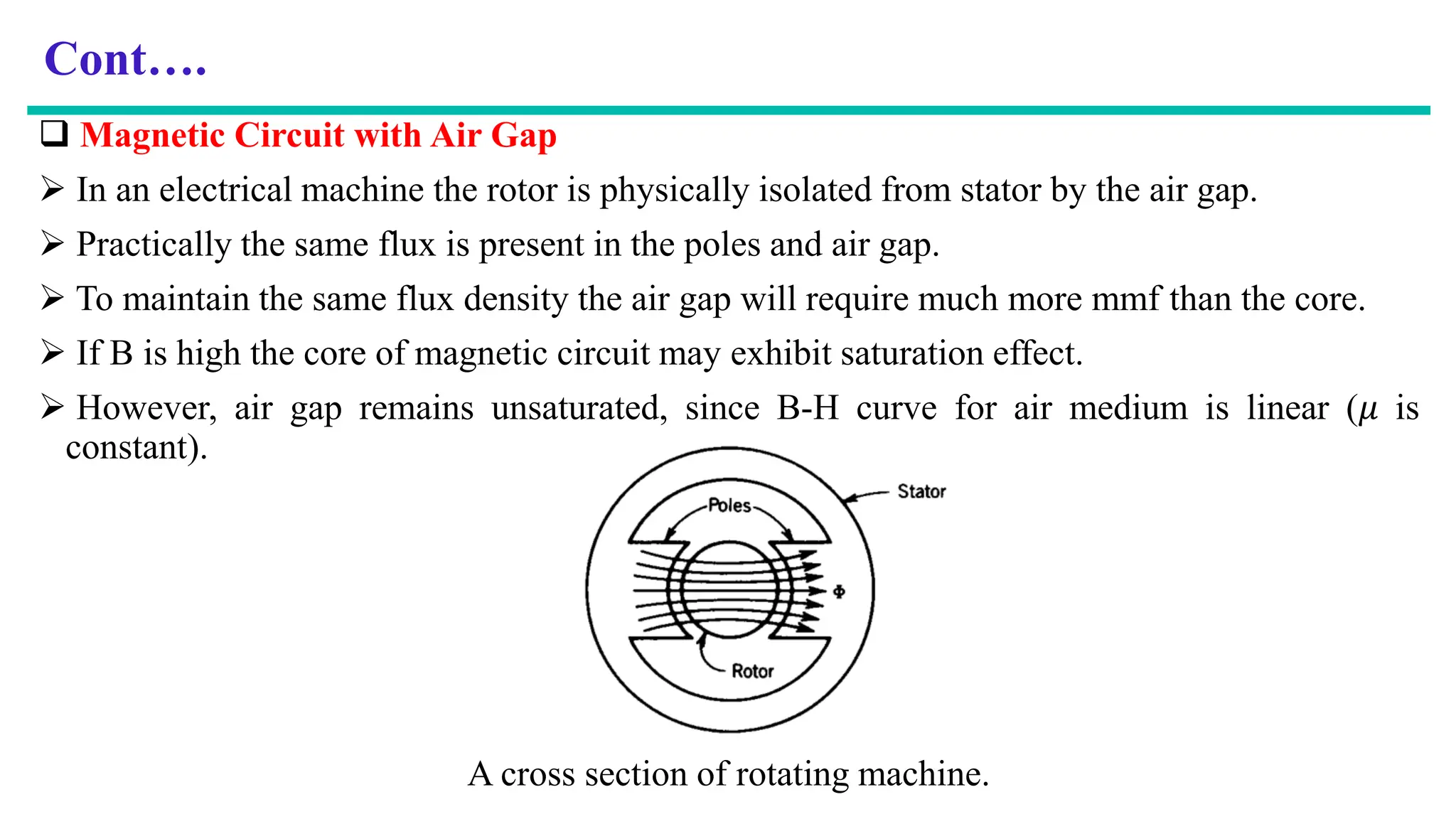
Magnetic Circuitwith Air Gap
In an electrical machine the rotor is physically isolated from stator by the air gap.
Practically the same flux is present in the poles and air gap.
To maintain the same flux density the air gap will require much more mmf than the core.
If B is high the core of magnetic circuit may exhibit saturation effect.
However, air gap remains unsaturated, since B-H curve for air medium is linear (𝜇 is
constant).
A cross section of rotating machine.
18.
Cont….
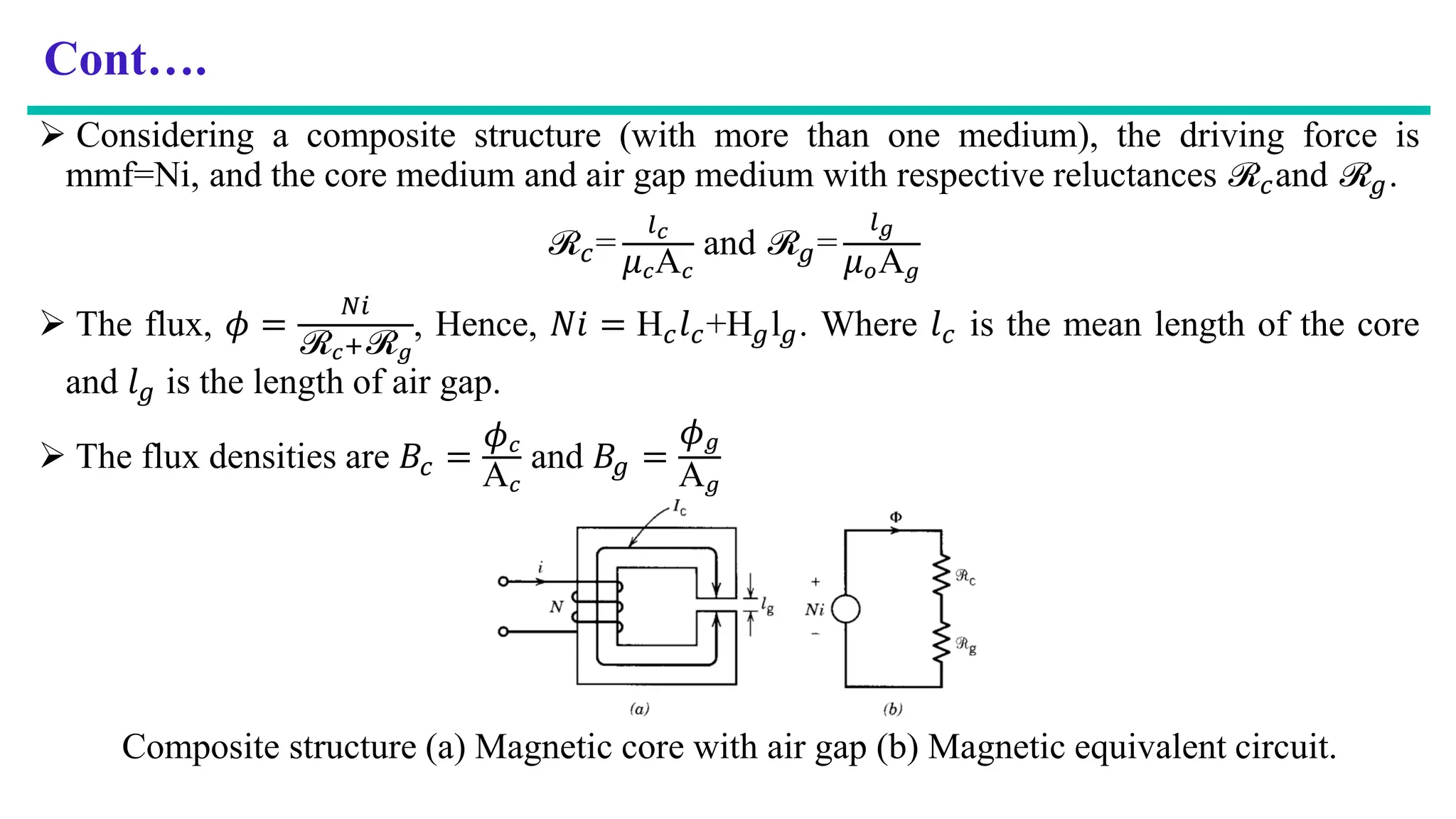
Considering acomposite structure (with more than one medium), the driving force is
mmf=Ni, and the core medium and air gap medium with respective reluctances ℛ𝑐and ℛ𝑔.
ℛ𝑐=
𝑙𝑐
𝜇𝑐A𝑐
and ℛ𝑔=
𝑙𝑔
𝜇𝑜A𝑔
The flux, 𝜙 =
𝑁𝑖
ℛ𝑐+ℛ𝑔
, Hence, 𝑁𝑖 = H𝑐𝑙𝑐+H𝑔l𝑔. Where 𝑙𝑐 is the mean length of the core
and 𝑙𝑔 is the length of air gap.
The flux densities are 𝐵𝑐 =
𝜙𝑐
A𝑐
and 𝐵𝑔 =
𝜙𝑔
A𝑔
Composite structure (a) Magnetic core with air gap (b) Magnetic equivalent circuit.
19.
Cont….
In theair gap magnetic flux lines bulge outward, this is called fringing of flux. The effect of
fringing increases the cross sectional area of the air gap.
For small air gaps the fringing effect can be neglected, so area of core is the same as area of
air gap. i.e. A𝑐 = A𝑔. So B𝑐 = B𝑔 =
𝜙
A𝑐
.
Example: The coil has 500 turns and the mean core path is l𝑐 = 360𝑚𝑚. When air gap
lengths are 1.5 mm each, a flux density of 0.8 tesla is required to actuate the relay. The core is
cast steel.
a, Find the current in the coil.
b, Compute the values of permeability and relative permeability of the core.
c, If air gap is zero, find the current in the coil for the same flux density of 0.8 T in the core.
Solution:
a, The air gap is small and so fringing can be neglected. Hence flux density, B is the same in
both air gap and core.
20.
Cont….
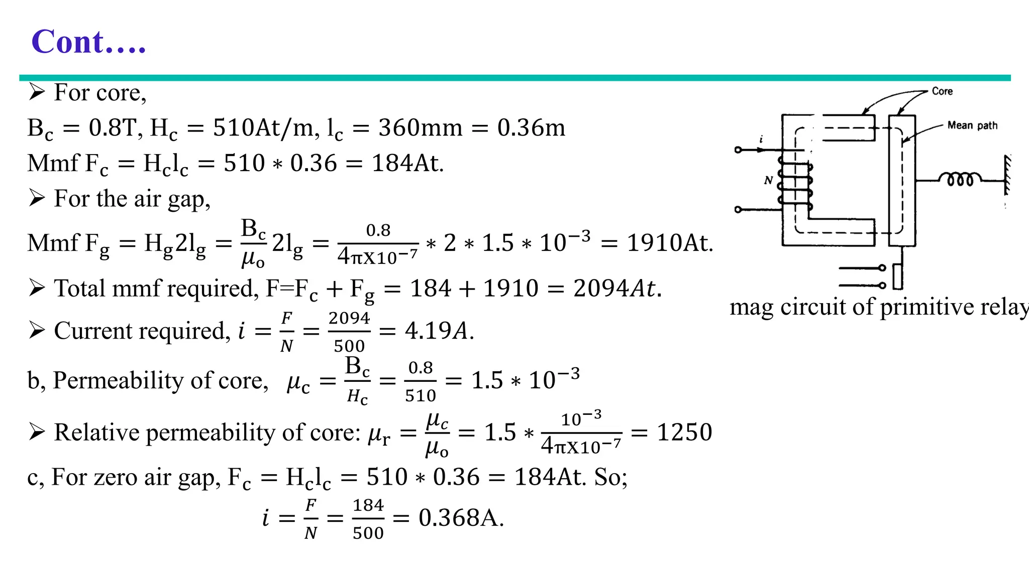
For core,
Bc= 0.8T, Hc = 510At/m, lc = 360mm = 0.36m
Mmf Fc = Hclc = 510 ∗ 0.36 = 184At.
For the air gap,
Mmf Fg = Hg2lg =
Bc
𝜇o
2lg =
0.8
4πx10−7 ∗ 2 ∗ 1.5 ∗ 10−3
= 1910At.
Total mmf required, F=Fc + Fg = 184 + 1910 = 2094𝐴𝑡.
Current required, 𝑖 =
𝐹
𝑁
=
2094
500
= 4.19𝐴.
b, Permeability of core, 𝜇c =
Bc
𝐻c
=
0.8
510
= 1.5 ∗ 10−3
Relative permeability of core: 𝜇r =
𝜇𝑐
𝜇o
= 1.5 ∗
10−3
4πx10−7 = 1250
c, For zero air gap, Fc = Hclc = 510 ∗ 0.36 = 184At. So;
𝑖 =
𝐹
𝑁
=
184
500
= 0.368A.
mag circuit of primitive relay
21.
Cont….
Note thatif the air gap is not present, a much smaller current is required to establish the same flux
density in the magnetic circuit.
There are two methods used to find magnetic flux density in magnetic circuit analysis. These are:
Load line method: 𝑁𝑖 = H𝑔l𝑔 + H𝑐𝑙𝑐 =
B𝑔
𝜇o
l𝑔 + H𝑐𝑙𝑐, rearranging, Bg = −𝜇o
𝑙c
lg
H𝑐 +
𝜇o𝑁𝑖
𝑙g
Try and error method:
a) Assume a flux density,
b) Calculate H𝑐 (from B-H curve) and 𝐻𝑔 (=
B𝑔
𝜇o
),
c) Calculate F𝑐 (=H𝑐 𝑙𝑐), F𝑐 (= H𝑐𝑙𝑐) and 𝐹 = F𝑐 + F𝑔,
d) Calculate i =
𝐹
𝑁
,
e) If i is different from the given current, assume other judicious value of flux density. Continue the
method until I is close to the given current.
Exercise: Consider the magnetic system of above example. If the coil current is 4A when each air gap
length is 1mm, find the flux density in the air gap.
22.
Cont….
A coilwound on a magnetic core, frequently used in electric circuits, is called inductor.
Inductance of inductor is given by: L =
𝞚
𝑖
=
𝑁𝛷
𝑖
=
𝑁BA
𝑖
=
𝑁𝜇𝐻A
𝑖
=
𝑁𝜇𝐻A
𝐻𝑙
𝑁
=
𝑁2𝜇A
𝑙
=
𝑁2
𝑙
𝜇A
=
𝑁2
ℛ
where, 𝞚 = 𝑁𝛷, 𝛷 = BA, 𝐵 = 𝜇𝐻, i =
𝐻𝑙
𝑁
,
𝑙
𝜇A
= ℛ.
Example: For the magnetic circuit with N=400 turns, mean core length, lc = 50𝑐𝑚, air gap
length, lg = 1𝑚𝑚, cross sectional area, Ac = A𝑔 = 15𝑐𝑚2, relative permeability of core,
𝜇r = 3000, and 𝑖 = 1𝐴. Find:
a) Flux and flux density in air gap, b) Inductance of the coil.
Solution:
a) ℛ𝑐=
𝑙𝑐
𝜇𝑐A𝑐
=
𝑙𝑐
𝜇𝑟𝜇𝑜A𝑐
=
50∗10−2
3000∗4πx10−7∗15∗10−4 = 88.42 ∗ 103𝐴𝑡/𝑊𝑏, and
ℛ𝑔=
𝑙𝑔
𝜇𝑜A𝑔
=
1∗10−3
4πx10−7∗15∗10−4 = 530.515 ∗ 103𝐴𝑡/𝑊𝑏.
23.
Cont….
𝜙 =
𝑁𝑖
ℛ𝑐 +ℛ𝑔
=
400 ∗ 1
(88.42 + 530.515) ∗ 103
= 0.6463 ∗ 10−3 𝑊𝑏.
B𝑔 =
𝜙
A𝑔
=
0.6463 ∗ 103
15 ∗ 10−4
= 0.4309 𝑇
b) L =
𝑁2
ℛ𝑐+ℛ𝑔
=
4002
(88.42+530.515)∗103 = 258.51 ∗ 10−3 𝐻 or
L =
𝞚
𝑖
=
𝑁𝛷
𝑖
=
400∗0.6463∗10−3
1
= 258.51 ∗ 10−3
𝐻.
Properties of Magnetic Materials
Magnetic Materials have certain important properties:
attractive property: Magnet attracts ferromagnetic materials like iron, cobalt, and nickel.
repulsive properties: Like magnetic poles repel each other and unlike magnetic poles attract
each other.
directive property: A freely suspended magnet always points in a north-south direction.
magnetic materials feel a non-contact magnetic force from a magnetic field.
24.
Cont….
Magnetic CoreLosses
Core loss is generated by the changing magnetic flux field within a material, since no
magnetic materials exhibit perfectly efficient magnetic response.
Hysteresis
Assuming initially unmagnetized coil core, and if the magnetic intensity, H is increased by
slowly increasing the current i, the flux density, B will change according to the curve 0a.
The point a corresponds to a particular value of magnetic intensity, H1 corresponding with
current i1.
If the magnetic intensity, H is now slowly decrease, the B-H curve will follow a different
path, such as abc. When H is made zero, the core has retained the flux density, B𝑟 known as
the residual flux density.
If H is reversed by reversing current i, 𝜙 in the core will decrease and for −H𝑐, 𝜙 will be
removed.
This magnetic intensity, −H𝑐 coercivity or coercive force of the magnetic core.
25.
Cont….
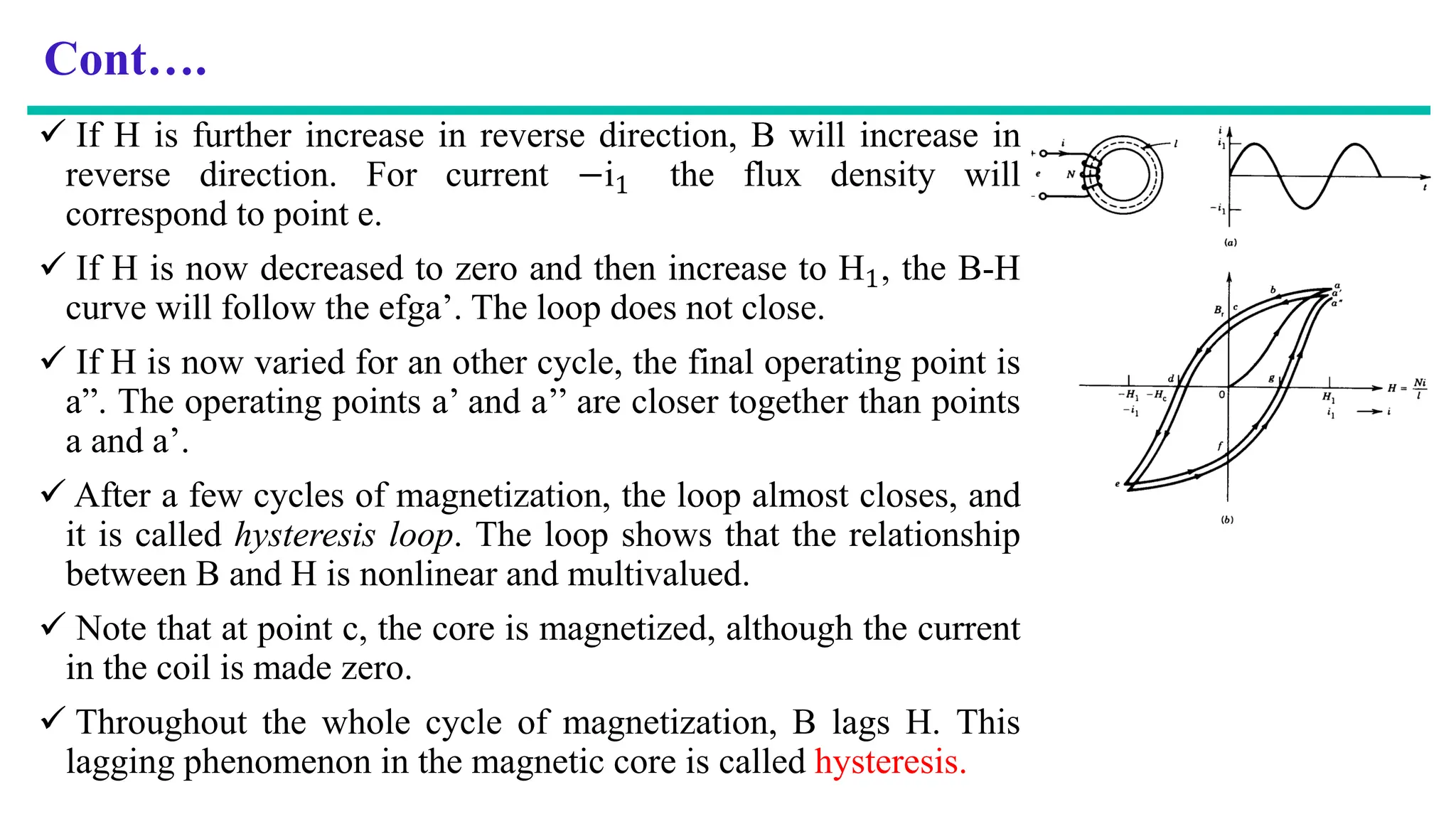
If His further increase in reverse direction, B will increase in
reverse direction. For current −i1 the flux density will
correspond to point e.
If H is now decreased to zero and then increase to H1, the B-H
curve will follow the efga’. The loop does not close.
If H is now varied for an other cycle, the final operating point is
a”. The operating points a’ and a’’ are closer together than points
a and a’.
After a few cycles of magnetization, the loop almost closes, and
it is called hysteresis loop. The loop shows that the relationship
between B and H is nonlinear and multivalued.
Note that at point c, the core is magnetized, although the current
in the coil is made zero.
Throughout the whole cycle of magnetization, B lags H. This
lagging phenomenon in the magnetic core is called hysteresis.
26.
Cont….
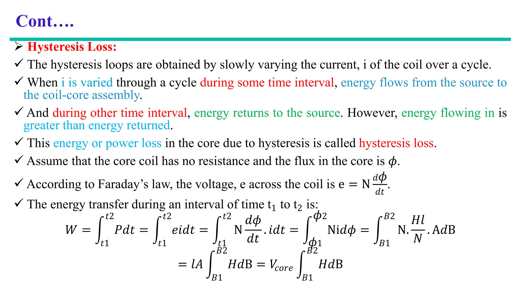
Hysteresis Loss:
The hysteresis loops are obtained by slowly varying the current, i of the coil over a cycle.
When i is varied through a cycle during some time interval, energy flows from the source to
the coil-core assembly.
And during other time interval, energy returns to the source. However, energy flowing in is
greater than energy returned.
This energy or power loss in the core due to hysteresis is called hysteresis loss.
Assume that the core coil has no resistance and the flux in the core is 𝜙.
According to Faraday’s law, the voltage, e across the coil is e = N
𝑑𝜙
𝑑𝑡
.
The energy transfer during an interval of time t1 to t2 is:
𝑊 = න
𝑡1
𝑡2
𝑃𝑑𝑡 = න
𝑡1
𝑡2
𝑒𝑖𝑑𝑡 = න
𝑡1
𝑡2
N
𝑑𝜙
𝑑𝑡
. 𝑖𝑑𝑡 = න
𝜙1
𝜙2
Ni𝑑𝜙 = න
𝐵1
𝐵2
N.
𝐻𝑙
𝑁
. A𝑑B
= 𝑙𝐴 න
𝐵1
𝐵2
𝐻𝑑B = 𝑉
𝑐𝑜𝑟𝑒 න
𝐵1
𝐵2
𝐻𝑑B
27.
Cont….
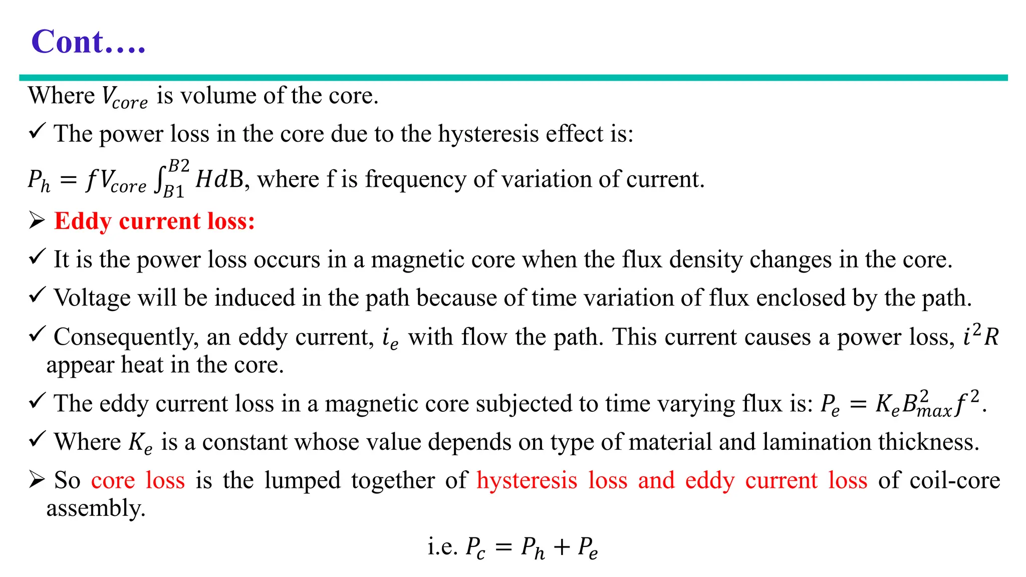
Where 𝑉
𝑐𝑜𝑟𝑒 isvolume of the core.
The power loss in the core due to the hysteresis effect is:
𝑃ℎ = 𝑓𝑉
𝑐𝑜𝑟𝑒
𝐵1
𝐵2
𝐻𝑑B, where f is frequency of variation of current.
Eddy current loss:
It is the power loss occurs in a magnetic core when the flux density changes in the core.
Voltage will be induced in the path because of time variation of flux enclosed by the path.
Consequently, an eddy current, 𝑖𝑒 with flow the path. This current causes a power loss, 𝑖2𝑅
appear heat in the core.
The eddy current loss in a magnetic core subjected to time varying flux is: 𝑃𝑒 = 𝐾𝑒𝐵𝑚𝑎𝑥
2 𝑓2.
Where 𝐾𝑒 is a constant whose value depends on type of material and lamination thickness.
So core loss is the lumped together of hysteresis loss and eddy current loss of coil-core
assembly.
i.e. 𝑃𝑐 = 𝑃ℎ + 𝑃𝑒
28.
Cont….
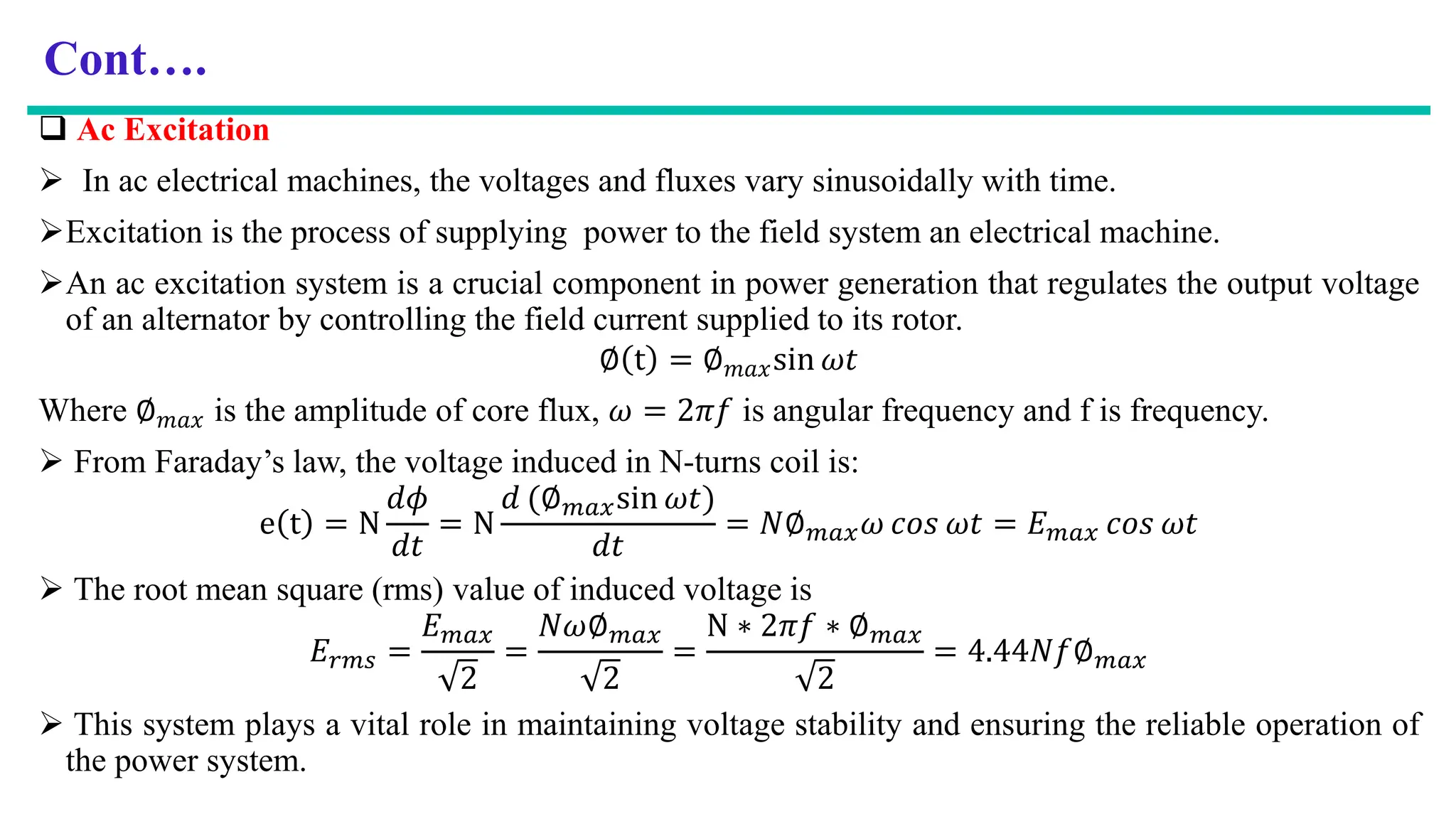
Ac Excitation
In ac electrical machines, the voltages and fluxes vary sinusoidally with time.
Excitation is the process of supplying power to the field system an electrical machine.
An ac excitation system is a crucial component in power generation that regulates the output voltage
of an alternator by controlling the field current supplied to its rotor.
∅ t = ∅𝑚𝑎𝑥sin 𝜔𝑡
Where ∅𝑚𝑎𝑥 is the amplitude of core flux, 𝜔 = 2𝜋𝑓 is angular frequency and f is frequency.
From Faraday’s law, the voltage induced in N-turns coil is:
e t = N
𝑑𝜙
𝑑𝑡
= N
𝑑 (∅𝑚𝑎𝑥sin 𝜔𝑡)
𝑑𝑡
= 𝑁∅𝑚𝑎𝑥𝜔 𝑐𝑜𝑠 𝜔𝑡 = 𝐸𝑚𝑎𝑥 𝑐𝑜𝑠 𝜔𝑡
The root mean square (rms) value of induced voltage is
𝐸𝑟𝑚𝑠 =
𝐸𝑚𝑎𝑥
2
=
𝑁𝜔∅𝑚𝑎𝑥
2
=
N ∗ 2𝜋𝑓 ∗ ∅𝑚𝑎𝑥
2
= 4.44𝑁𝑓∅𝑚𝑎𝑥
This system plays a vital role in maintaining voltage stability and ensuring the reliable operation of
the power system.
29.
Cont….
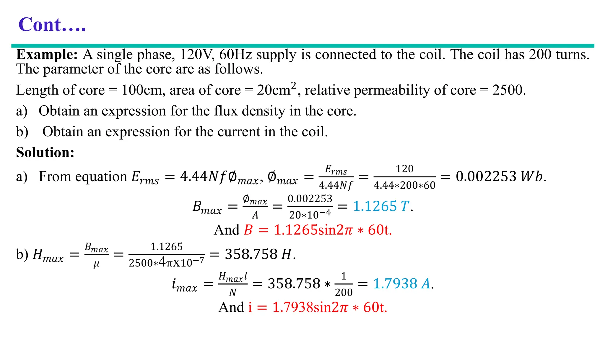
Example: A singlephase, 120V, 60Hz supply is connected to the coil. The coil has 200 turns.
The parameter of the core are as follows.
Length of core = 100cm, area of core = 20cm2, relative permeability of core = 2500.
a) Obtain an expression for the flux density in the core.
b) Obtain an expression for the current in the coil.
Solution:
a) From equation 𝐸𝑟𝑚𝑠 = 4.44𝑁𝑓∅𝑚𝑎𝑥, ∅𝑚𝑎𝑥 =
𝐸𝑟𝑚𝑠
4.44𝑁𝑓
=
120
4.44∗200∗60
= 0.002253 𝑊𝑏.
𝐵𝑚𝑎𝑥 =
∅𝑚𝑎𝑥
𝐴
=
0.002253
20∗10−4 = 1.1265 𝑇.
And 𝐵 = 1.1265sin2𝜋 ∗ 60t.
b) 𝐻𝑚𝑎𝑥 =
𝐵𝑚𝑎𝑥
𝜇
=
1.1265
2500∗4πx10−7 = 358.758 𝐻.
𝑖𝑚𝑎𝑥 =
𝐻𝑚𝑎𝑥𝑙
𝑁
= 358.758 ∗
1
200
= 1.7938 𝐴.
And i = 1.7938sin2𝜋 ∗ 60t.
30.
Cont….
Permanent Magnets
A permanent magnet is a capable of maintaining magnetic field with out any excitation mmf
provided to it.
Permanent magnets are magnetic materials that exhibit a persistent magnetic field without
the need for an external source.
They are not easily demagnetized and can generate their own magnetic filed.
Types of permanent magnets include:
natural Magnets (Magnetite); and
artificial Magnets (aluminum-nickel-cobalt alloy). These modern magnets are made from a
combination of iron, neodymium, samarium, cobalt and nickel.
Permanent magnets are characterized by:
Large B-H loop,
High retentivity (High value of 𝐵𝑟), and
High coercive force (High value of 𝐻𝑐).