Download to read offline
![IOSR Journal of Electronics and Communication Engineering (IOSR-JECE)
e-ISSN: 2278-2834,p- ISSN: 2278-8735.Volume 10, Issue 6, Ver. II (Nov - Dec .2015), PP 114-120
www.iosrjournals.org
DOI: 10.9790/2834-1062114120 www.iosrjournals.org 114 | Page
Gain Analysis of EDF Amplifier Based WDM System Using
Different PumpingWavelength
Vishal Srivastava1
, Munish Singh2
1
M-Tech Student ECE, Lovely Professional University, Punjab, India 2
Assistant Professor, ECE, Lovely
Professional University, India
Abstract: This report describes the simulation model of Erbium doped fiber amplifier (EDFA) with different
pump power (250mw,300mw,up to 500mw) with optimized gain and maintained noise figure is obtained by
using single pumping (backward pumping) with the wavelength 980nm and 1480nm pumping wavelength and
the results are plotted with various fiber length and pump power. The performance of the EDFA based WDM
system has been evaluated in terms of different parameter such as gain, gain flatness, and noise figure. The
system has a wide variety of research in next generation networks. The EDFA optical amplifier system is
require less input power so such systems are easy to evaluate and provide high gain and less noise figure. Many
factors i.e. gain flatness, noise figure and bit error rate (BER) may influence the performance of such systems.
In this research, the gain is being optimized in terms of different fiber length and pump power. The system is
simulated on Opti- system software to analyze the gain flatness bit error rate and noise figure of EDFA through
optimized fiber length and pump power. The gain is flattened within 39±0.25dB and noise figure<5dB for 16
channels from 1546nm to 1558nm range of wavelength with the channel spacing of 0.8nm are simultaneously
operating with the single stage EDFA with a constant input power -26dB.
Keywords: EDFA, gain flatness, fiber length, pump power, WDM, single pumping,pumping wavelength.
I. Introduction
Optical Amplifier is a device that amplifies an optical signal (as input signal) directly in optical form
without the need of first convert it into an electrical signal. There are so many optical amplifier are used in
telecommunication but here we do the gain analysis of Erbium-doped fiber amplifier (EDFA) using WDM
system. Now a days, Internet services requires large bandwidth, so EDFA’s are used in WDM Technology
which increases the optical network capacity without affecting the cost. Wavelength-division multiplexing
(WDM) is the kind of the multiplexer that is intended to use multiple number of sources that are bound to
operate at different wavelengths for transmission of several independent information streams over the same fiber
in simultaneous manner. The fiber transmission capacity is further enhanced using WDM. In WDM system the
wavelengths over C-band and L-band are amplified to require power level where the amplification of the
particular channel depends on [1] :
Signal wavelength
Number of signal present in system
Input signal power
Since the WDM device need to operate at electronic speed commonly, it is easier to implement any
WDM devices.
II. System Description
Erbium Doped Fiber Amplifier (EDFA) is a Optical Amplifier that uses a fiber which has been lightly
doped with rare earth ion (i.e.erbium). It is uses this doped optical fiber as a gain medium to amplify an optical
signal. The signal to be amplified and a pump laser are multiplexed into a doped fiber and the signal is amplified
through interaction with doping ions.The EDFA having limited range (10m to 30m) [2]. The operation of
standard EDFA normally is limited to 1530 to 1560 nm region, this region is known as C-band (Conventional
band). For simultaneous amplification of various data channel having different wavelengths in different gain
regions a single EDFA is used. Before the development of such fiber amplifiers there was no such practical
method available for the process of amplification of the channels between long fiber spans of fiber optics link
[3].Several methods used for the purpose of designing flat spectral gain EDFA are :](https://image.slidesharecdn.com/p01062114120-160806044903/85/P01062114120-1-320.jpg)
![IOSR Journal of Electronics and Communication Engineering (IOSR-JECE)
e-ISSN: 2278-2834,p- ISSN: 2278-8735.Volume 10, Issue 6, Ver. II (Nov - Dec .2015), PP 114-120
www.iosrjournals.org
DOI: 10.9790/2834-1062114120 www.iosrjournals.org 114 | Page
Gain Analysis of EDF Amplifier Based WDM System Using
Different PumpingWavelength
Vishal Srivastava1
, Munish Singh2
1
M-Tech Student ECE, Lovely Professional University, Punjab, India 2
Assistant Professor, ECE, Lovely
Professional University, India
Abstract: This report describes the simulation model of Erbium doped fiber amplifier (EDFA) with different
pump power (250mw,300mw,up to 500mw) with optimized gain and maintained noise figure is obtained by
using single pumping (backward pumping) with the wavelength 980nm and 1480nm pumping wavelength and
the results are plotted with various fiber length and pump power. The performance of the EDFA based WDM
system has been evaluated in terms of different parameter such as gain, gain flatness, and noise figure. The
system has a wide variety of research in next generation networks. The EDFA optical amplifier system is
require less input power so such systems are easy to evaluate and provide high gain and less noise figure. Many
factors i.e. gain flatness, noise figure and bit error rate (BER) may influence the performance of such systems.
In this research, the gain is being optimized in terms of different fiber length and pump power. The system is
simulated on Opti- system software to analyze the gain flatness bit error rate and noise figure of EDFA through
optimized fiber length and pump power. The gain is flattened within 39±0.25dB and noise figure<5dB for 16
channels from 1546nm to 1558nm range of wavelength with the channel spacing of 0.8nm are simultaneously
operating with the single stage EDFA with a constant input power -26dB.
Keywords: EDFA, gain flatness, fiber length, pump power, WDM, single pumping,pumping wavelength.
I. Introduction
Optical Amplifier is a device that amplifies an optical signal (as input signal) directly in optical form
without the need of first convert it into an electrical signal. There are so many optical amplifier are used in
telecommunication but here we do the gain analysis of Erbium-doped fiber amplifier (EDFA) using WDM
system. Now a days, Internet services requires large bandwidth, so EDFA’s are used in WDM Technology
which increases the optical network capacity without affecting the cost. Wavelength-division multiplexing
(WDM) is the kind of the multiplexer that is intended to use multiple number of sources that are bound to
operate at different wavelengths for transmission of several independent information streams over the same fiber
in simultaneous manner. The fiber transmission capacity is further enhanced using WDM. In WDM system the
wavelengths over C-band and L-band are amplified to require power level where the amplification of the
particular channel depends on [1] :
Signal wavelength
Number of signal present in system
Input signal power
Since the WDM device need to operate at electronic speed commonly, it is easier to implement any
WDM devices.
II. System Description
Erbium Doped Fiber Amplifier (EDFA) is a Optical Amplifier that uses a fiber which has been lightly
doped with rare earth ion (i.e.erbium). It is uses this doped optical fiber as a gain medium to amplify an optical
signal. The signal to be amplified and a pump laser are multiplexed into a doped fiber and the signal is amplified
through interaction with doping ions.The EDFA having limited range (10m to 30m) [2]. The operation of
standard EDFA normally is limited to 1530 to 1560 nm region, this region is known as C-band (Conventional
band). For simultaneous amplification of various data channel having different wavelengths in different gain
regions a single EDFA is used. Before the development of such fiber amplifiers there was no such practical
method available for the process of amplification of the channels between long fiber spans of fiber optics link
[3].Several methods used for the purpose of designing flat spectral gain EDFA are :](https://image.slidesharecdn.com/p01062114120-160806044903/75/P01062114120-1-2048.jpg)
![Gain Analysis of EDFAmplifier Based WDM System Using Different PumpingWavelength
DOI: 10.9790/2834-1062114120 www.iosrjournals.org 115 | Page
By controlling doped fiber length, pump power and choosing proper optical notch for filters characteristics.
By employing homogenous broadened gain medium
By using acousto-optic tunable fiber
Fig. 1.1: Basic block diagram of an EDFA
EDFA-WDM system stimulated using Opti-system software to achieve the gain flatness of EDFA
through optimized fiber length and pump power. The gains are flattened within 39±0.5 dB from 1546nm to
1558nm band of wavelength with noise figure (NF)<6dB for 16-channels simultaneous amplification in a single
stage EDFA with channel spacing 0.8nm. The gain is optimized using a single pumping with the wavelength
980nm. The 980nm pumping yields a complete population inversion (maximum gain) at shorter amplifier
lengths than 1480nm pumping. This leads to a lower amplifiers noise figure when using 980 nm pumping [4][5].
III. Motivation Of Research Work
In analyzing and designing optical network there are several methods can be used. For this EDFA
(Erbium doped fiber amplifier) gain optimization for WDM (Wavelength Division Multiplexer) system optical
network, used simulation approach rather than fabrication methods. Simulator allows engineers to design the
most correct and efficient design before the actual optical network constructed. Moreover, able to explore the
merits of other design without physically build it. Besides, by using simulation method engineers able to study
problem that occur during designing the optical network. Before starts to design, need to identify the best
simulators software that is suitable to design this optical network. After comparing advantages and
disadvantages between Opti- system and MATLAB, Opti-system software was selected to be used in designing
EDFA in WDM system. Opti- system is a comprehensive simulation package developed by Opti-wave[6]. This
software enables users to plan, test, and simulate optical links in the transmission layer of modern optical
networks. A robust graphical user interface controls the optical component layout, component models and
presentation graphics. An extensive library of active and passive components includes realistic, wavelength-
dependent parameters. Parameters sweeps allow us to investigate the effect of particular device specifications on
systemperformance [7][8].
The applied methodology is based on Backward Single Pumping approach. Each block in the
architecture was added in the model and tested and later those blocks were assembled and were added to
compose.
IV. Research Methodology
A relatively high-powered beam of light is mixed with the input signal using a wavelength selective
coupler. The input signal and the excitation light must be at significantly different wavelengths [9]. The mixed
light is guided into a section of fiber with erbium ions included in the core. This high-powered light beam
excites the erbium ions to their higher-energy state. When the photons belonging to the signal at a different
wavelength from the pump light meet the excited erbium atoms, the erbium atoms give up some of their energy
to the signal and return to their lower-energy state[10].](https://image.slidesharecdn.com/p01062114120-160806044903/85/P01062114120-2-320.jpg)
![Gain Analysis of EDFAmplifier Based WDM System Using Different PumpingWavelength
DOI: 10.9790/2834-1062114120 www.iosrjournals.org 116 | Page
Fig. 1.2 Flowchart of EDFA amplifying process
V. Proposed Work And Result
In analyzing and designing optical network there are several methods can be used. For this EDFA
(Erbium doped fiber amplifier) gain optimization for WDM (Wavelength Division Multiplexer) system optical
network, used simulation approach rather than fabrication methods. Simulator allows engineers to design the
most correct and efficient design before the actual optical network constructed. Moreover [11], able to explore
the merits of other design without physically build it. Besides, by using simulation method engineers are able to
study problem that occur during designing the optical network .The pump power is taken in a range of 250mw-
500mw while the fiber length is bound between 2 to 22m. In other hand, the 16 input channels with a spacing of
0.8nm from 1546nm to 1558nm were simultaneously operated on a single fiber with a constant input power i.e.
26dBm. The reference pup power is set to be 120mw. After that it is measured at different pump power such as
250mw,300mw etc, with an increment of 50mw up to 500mw [12]. The pumping wavelength is 980nm. the
reference power is set to 120mw for the measurement of different fiber length to find the optimized length of
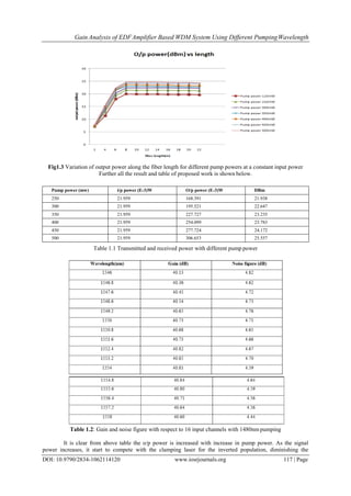
fiber for amplifier used in this system as show in table1.A suitable length of fiber is 8m is chosen as an optimum
length for this system because at 8m the output power gave the maximum value at the reference power.
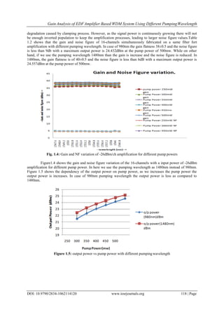
Therefore, the gain and noise figure are measured at 8m length with different pump power as shown in Fig 1.3
[13].](https://image.slidesharecdn.com/p01062114120-160806044903/85/P01062114120-3-320.jpg)
![Gain Analysis of EDFAmplifier Based WDM System Using Different PumpingWavelength
DOI: 10.9790/2834-1062114120 www.iosrjournals.org 120 | Page
References
[1]. M.M.Ismail et al, “EDFA-WDM Optical Network Design System”, In SciVerse Science Direct, Malaysian Technical Universities
Conference on Engineering And Technology 2012, MUCET2012.
[2]. Farah Diana Binti Mahad et al, “EDFA Gain Optimization for WDM System”, In ELEKTRIKA Department of Optic and
Telematics Engineering, Vol.11,No.1,-2009.
[3]. S.Semmalar et al, “Optimized Gain EDFA of different lengths with an influence of pumping power”, In Engineering college,
puducherry,India.
[4]. B.Nagaraju et al, “Design and fabrication of an asymmetric twin-core fiber directional coupler for gain- flattened EDFA”, In
physics department, India institute of technology delhi, CNRS 6622 parc valrose, F 06108 NICE cedex2, France.
[5]. Hirotaka Ono, “Wide-Range Variable Gain Fiber Amplifier With Erbium-Doped Fiber Switching”, in journal of light wave
technology, vol. 13, No.12, june15,2013.
[6]. Liu Liying, Ma Yu, Yang Jiuru “Performance Optimization based Spectrum Analysis on OFRA and EDFA Devices” P.R. China
TELKOMNIKA, Vol. 11, No. 7, July 2013, pp. 3742~3749 e-ISSN: 2087- 278X.
[7]. Simranjit Singh, R.S. Kaler “Multistage gain-flattened hybrid optical amplifier at reduced wavelength spacing”.2014.06.030030-
4026/© 2014 Elsevier GmbH. All rightsreserved.
[8]. Deepika Verma et al, “Gain Flatness and Bit Error Rate Improvements for an EDFA in WDM System”, In International Journal of
Enhanced Research in Science Technology & Engineering,Vol.3 Issue 5, May-2014.
[9]. Hirotaka Ono, “Wide-Range Variable Gain Fiber Amplifier With Erbium-Doped Fiber Switching”, in journal of light wave
technology, vol. 13, No.12, june15,2013.
[10]. G. Keiser,” Optical Fiber Communication”, Third Edition,2000.
[11]. Shweta Bharti, “EDFA WDM Optical Network using GFF”, In International Journal of Enhanced Research in Science Technology
& Engineering,Vol.3 Issue 8,August-2014.
[12]. C. R. Giles and E. Desurvire, “Modeling Erbium Doped Fiber Amplifiers”, IEEE Journal of Light wave Technology, vol.9, pp.271-
283, 1991.
[13]. M. N. Islam, “Raman Amplifiers for Telecommunications”, IEEE Journal of Selected Topics in Quantum Electronics, vol.8, pp.
548-559, 2002.](https://image.slidesharecdn.com/p01062114120-160806044903/85/P01062114120-7-320.jpg)

This document summarizes research on optimizing the gain of an erbium-doped fiber amplifier (EDFA) based wavelength division multiplexing (WDM) system using different pumping wavelengths. The EDFA-WDM system was simulated using OptiSystem software to analyze gain flatness, noise figure, and bit error rate for 16 channels simultaneously amplified using a single EDFA stage. Pumping wavelengths of 980nm and 1480nm were compared, with 1480nm pumping achieving gain flatness of 40±0.5dB and noise figure below 6dB across all channels. Output power was found to increase with higher pump power, up to 24.557dBm at 500mW of pump power for 1480


