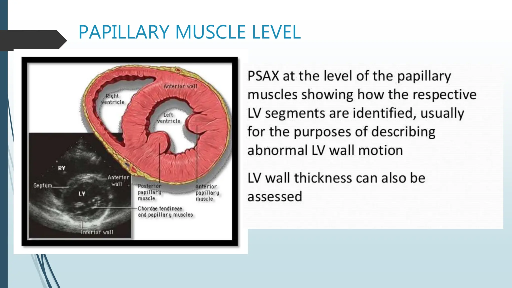
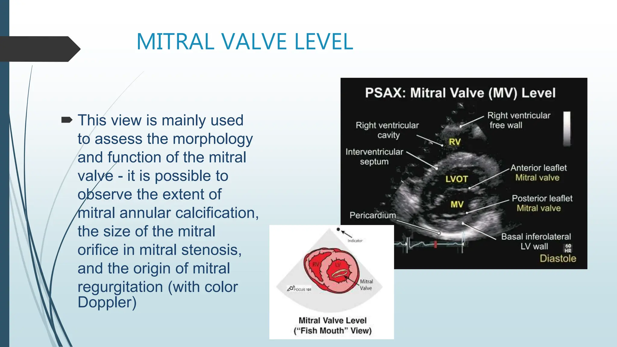
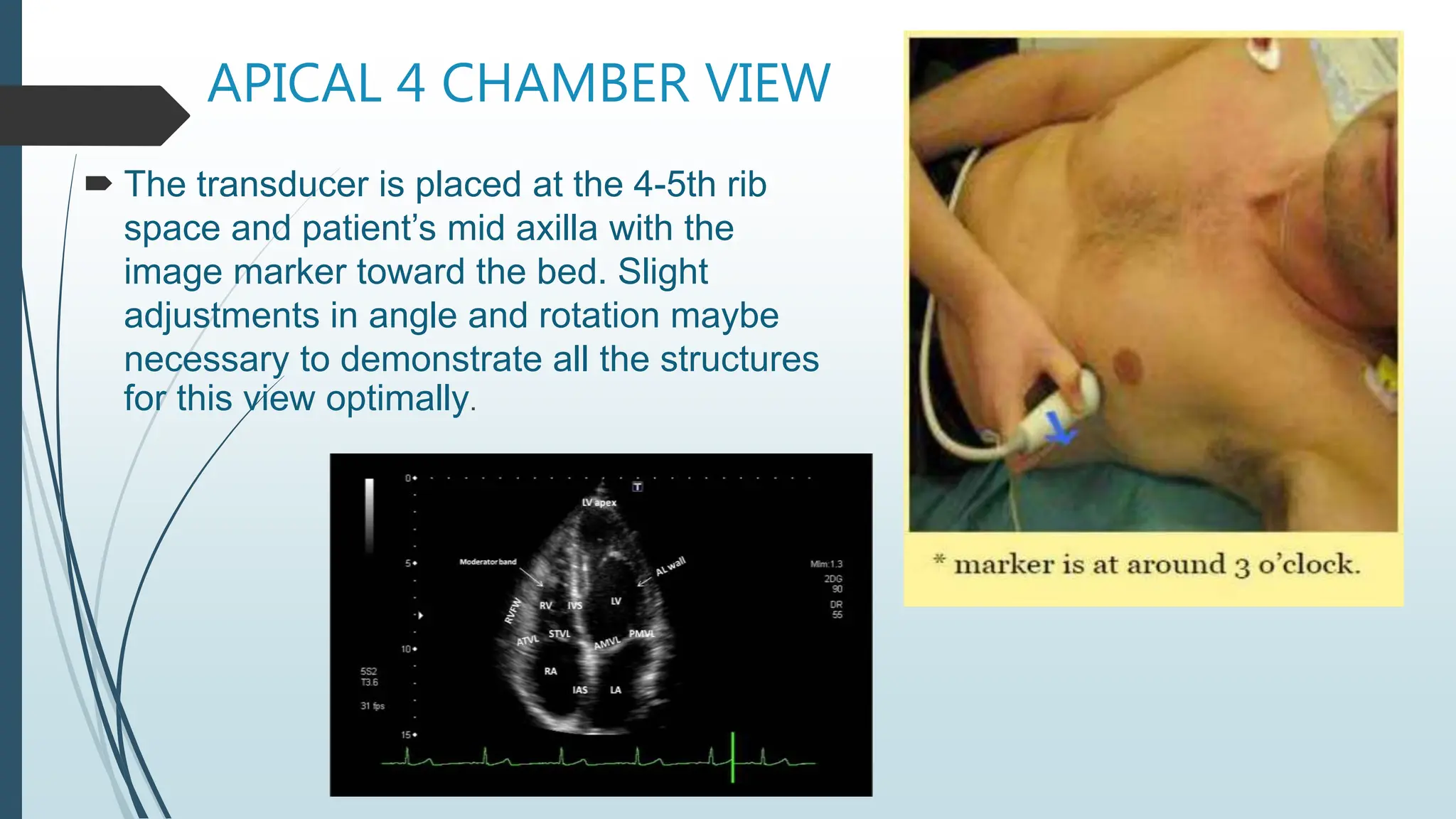
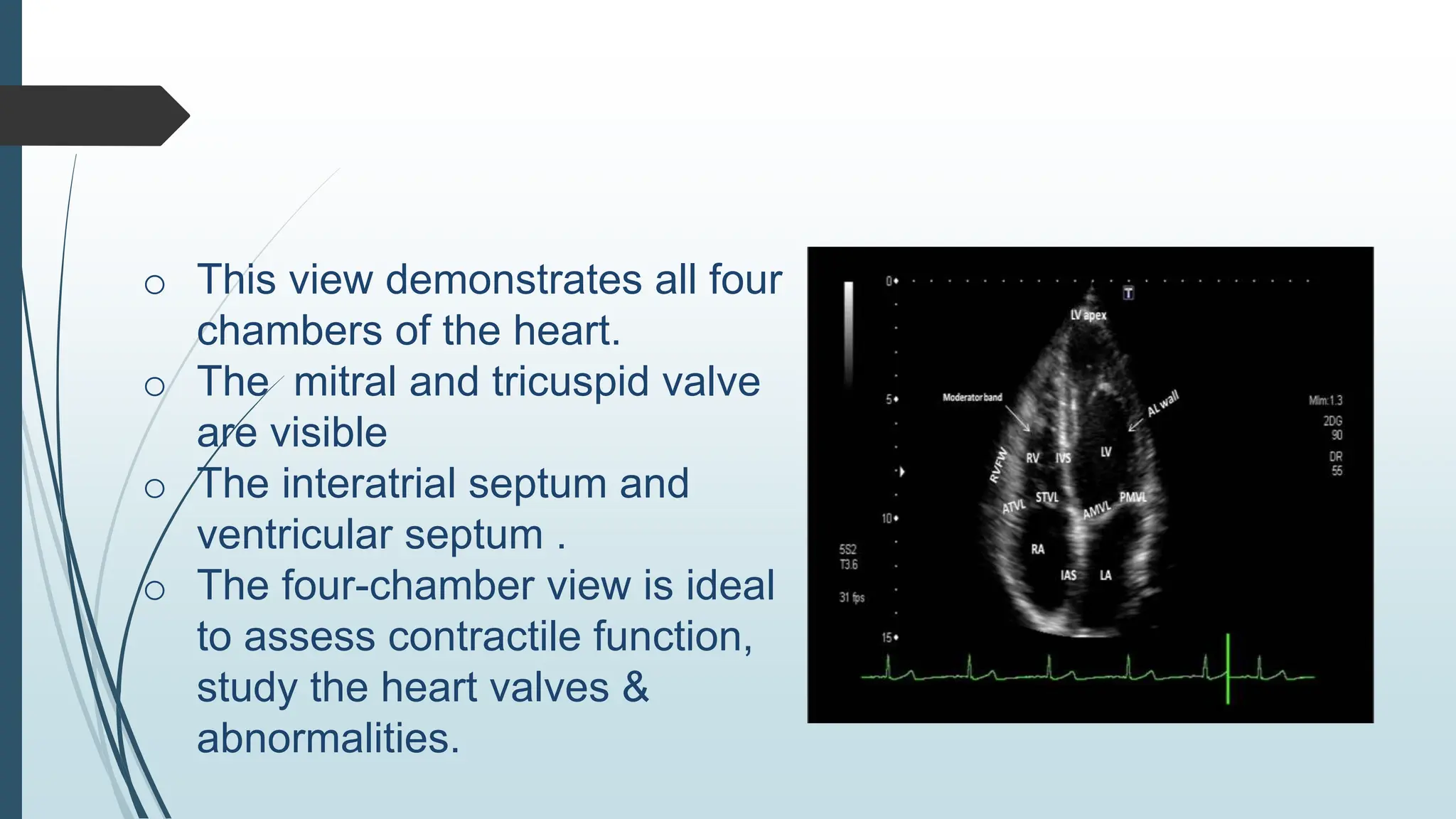
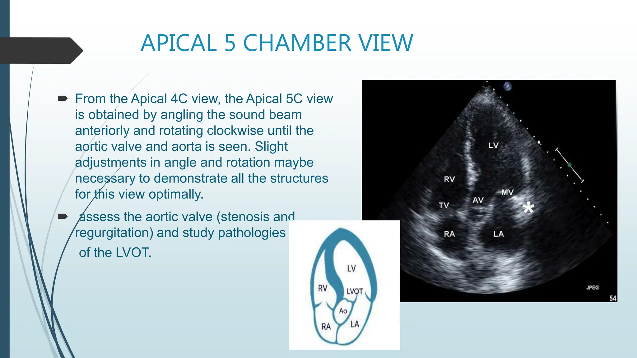
ECHOCARDIOGRAPHY
WINDOWS AND VIEWS
BY: RUTVI THAKER
3rd YEAR BSC CARDIAC CARE TECHNOLOGY
INTRODUCTION
 An echocardiography, is an ultrasound of the heart. It is a type of medical
imaging of the heart, using standard ultrasound.
 Echocardiography has become routinely used in the diagnosis,
management, and follow-up of patients with any suspected or known heart
disease.
 It can provide information about :
o Heart chambers
o Pumping capacity
o Extent of any tissue damage
o Assessment of valves and cardiac masses
o Cardiac output
o Ejection fraction
o Systolic & Diastolic function.
PRINCIPLE
Echo studies are carried out using high-frequency
sound waves (about 1.5MHz -7.5MHz). the sound
waves of different frequencies is transmitted from a
device called a Transducer (probe).
 The sound waves bounce off of the heart and return
to the transducer as echoes. The echoes are
converted into images on a television monitor to
produce pictures of your heart in motion.
ULTRASOUND PRODUCTION AND
DETECTION
 Ultrasound results from the property of certain crystals to transform electrical
oscillations (varying voltages) into mechanical oscillations (sound). This is called the
piezoelectric effect.
 The same crystals can also act as ultrasound receivers since they can effect the
transformation in the opposite direction (mechanical to electrical). The repetition
rate is 1000/second.
VIEWING THE HEART
 Transducer (probe) which is placed on the subject’s
anterior chest wall. This is Transthoracic echo (TTE).
 The transducer usually has a line or dot to help rotate
it into the correct position to give different echo
views. The subject usually lies in the Left lateral
position and ultrasound jelly is placed on the
transducer to ensure good images.
 Continuous electrocardiograph (ECG) recording is
performed and phonocardiography may be used to
time cardiac events. An echo examination usually
takes 15–20 min.
ECHO WINDOWS & VIEWS
 MAIN ECHO WINDOWS
VIEWS
Image obtain in the long axis, slice the heart
form base to the apex.
Parasternal long axis view showing the
dense calcification of anterior mitral leaflet
(AML) with commissural fusion in a 52-year-
old male.
2.
AROTIC VALVE LEVEL
PAPILLARY MUSCLE LEVEL
MITRAL VALVE LEVEL
 This view is mainly used
to assess the morphology
and function of the mitral
valve - it is possible to
observe the extent of
mitral annular calcification,
the size of the mitral
orifice in mitral stenosis,
and the origin of mitral
regurgitation (with color
Doppler)
APICAL 4 CHAMBER VIEW
 The transducer is placed at the 4-5th rib
space and patient’s mid axilla with the
image marker toward the bed. Slight
adjustments in angle and rotation maybe
necessary to demonstrate all the structures
for this view optimally.
o This view demonstrates all four
chambers of the heart.
o The mitral and tricuspid valve
are visible
o The interatrial septum and
ventricular septum .
o The four-chamber view is ideal
to assess contractile function,
study the heart valves &
abnormalities.
APICAL 5 CHAMBER VIEW
 From the Apical 4C view, the Apical 5C view
is obtained by angling the sound beam
anteriorly and rotating clockwise until the
aortic valve and aorta is seen. Slight
adjustments in angle and rotation maybe
necessary to demonstrate all the structures
for this view optimally.
 assess the aortic valve (stenosis and
regurgitation) and study pathologies
of the LVOT.
2 CHAMBER VIEW
 the transducer notch turned 60-90
(usually 90) degrees from the Four
Chamber position, pointed toward
the left shoulder.
 The right atrium and right
ventricle fall out of view, and the
left atrium and anterior and inferior
walls of the left ventricle are
visualized.
3 CHAMBER OR LONG AXIS VIEW
 The probe is placed in the fourth intercostal space. The tip of the
transducer is rotated counter clockwise from the Apical Two Chamber
view to about 120 degrees.
Subcostal Short-Axis View
 By rotating the transducer counterclockwise you can create
short-axis views. Short-axis views can be obtained at different
levels by moving the transducer more to the left to view the
ventricular segments, and to the right to view the basal
segments.
 structures see the pulmonary valve and the pulmonary artery.
Subcostal vena cava view
 To obtain the subcostal view of the inferior vena cava is to start with a four-
chamber view. Make sure the right atrium is in the center of the image. Then
rotate the transducer counterclockwise and direct it to the right. The subcostal
view shows the vena cava inferior in a "long axis".
 Assessing the size and blood flow of the inferior vena cava and the hepatic
veins, you can identify a prominent Eustachian valve, a pericardial effusion, or
a (right-sided) pleural effusion.
• The suprasternal long axis shows the ascending aorta (on the left of the
image), the aortic arch with the brachiocephalic artery (common trunk),
the left common carotid artery, the left subclavian artery and the cranial
segment of the descending aorta (on the right).
Measure the width of the aortic arch
Look for aortic dissection or coarctation
Assess retrograde flow in the descending aorta

echocardiograhy window and views at large

  • 1.
    ECHOCARDIOGRAPHY WINDOWS AND VIEWS BY:RUTVI THAKER 3rd YEAR BSC CARDIAC CARE TECHNOLOGY
  • 2.
    INTRODUCTION  An echocardiography,is an ultrasound of the heart. It is a type of medical imaging of the heart, using standard ultrasound.  Echocardiography has become routinely used in the diagnosis, management, and follow-up of patients with any suspected or known heart disease.  It can provide information about : o Heart chambers o Pumping capacity o Extent of any tissue damage o Assessment of valves and cardiac masses o Cardiac output o Ejection fraction o Systolic & Diastolic function.
  • 3.
    PRINCIPLE Echo studies arecarried out using high-frequency sound waves (about 1.5MHz -7.5MHz). the sound waves of different frequencies is transmitted from a device called a Transducer (probe).  The sound waves bounce off of the heart and return to the transducer as echoes. The echoes are converted into images on a television monitor to produce pictures of your heart in motion.
  • 4.
    ULTRASOUND PRODUCTION AND DETECTION Ultrasound results from the property of certain crystals to transform electrical oscillations (varying voltages) into mechanical oscillations (sound). This is called the piezoelectric effect.  The same crystals can also act as ultrasound receivers since they can effect the transformation in the opposite direction (mechanical to electrical). The repetition rate is 1000/second.
  • 5.
    VIEWING THE HEART Transducer (probe) which is placed on the subject’s anterior chest wall. This is Transthoracic echo (TTE).  The transducer usually has a line or dot to help rotate it into the correct position to give different echo views. The subject usually lies in the Left lateral position and ultrasound jelly is placed on the transducer to ensure good images.  Continuous electrocardiograph (ECG) recording is performed and phonocardiography may be used to time cardiac events. An echo examination usually takes 15–20 min.
  • 6.
    ECHO WINDOWS &VIEWS  MAIN ECHO WINDOWS
  • 7.
    VIEWS Image obtain inthe long axis, slice the heart form base to the apex.
  • 9.
    Parasternal long axisview showing the dense calcification of anterior mitral leaflet (AML) with commissural fusion in a 52-year- old male.
  • 10.
  • 12.
  • 13.
  • 14.
    MITRAL VALVE LEVEL This view is mainly used to assess the morphology and function of the mitral valve - it is possible to observe the extent of mitral annular calcification, the size of the mitral orifice in mitral stenosis, and the origin of mitral regurgitation (with color Doppler)
  • 15.
    APICAL 4 CHAMBERVIEW  The transducer is placed at the 4-5th rib space and patient’s mid axilla with the image marker toward the bed. Slight adjustments in angle and rotation maybe necessary to demonstrate all the structures for this view optimally.
  • 16.
    o This viewdemonstrates all four chambers of the heart. o The mitral and tricuspid valve are visible o The interatrial septum and ventricular septum . o The four-chamber view is ideal to assess contractile function, study the heart valves & abnormalities.
  • 17.
    APICAL 5 CHAMBERVIEW  From the Apical 4C view, the Apical 5C view is obtained by angling the sound beam anteriorly and rotating clockwise until the aortic valve and aorta is seen. Slight adjustments in angle and rotation maybe necessary to demonstrate all the structures for this view optimally.  assess the aortic valve (stenosis and regurgitation) and study pathologies of the LVOT.
  • 19.
    2 CHAMBER VIEW the transducer notch turned 60-90 (usually 90) degrees from the Four Chamber position, pointed toward the left shoulder.  The right atrium and right ventricle fall out of view, and the left atrium and anterior and inferior walls of the left ventricle are visualized.
  • 20.
    3 CHAMBER ORLONG AXIS VIEW  The probe is placed in the fourth intercostal space. The tip of the transducer is rotated counter clockwise from the Apical Two Chamber view to about 120 degrees.
  • 23.
    Subcostal Short-Axis View By rotating the transducer counterclockwise you can create short-axis views. Short-axis views can be obtained at different levels by moving the transducer more to the left to view the ventricular segments, and to the right to view the basal segments.  structures see the pulmonary valve and the pulmonary artery.
  • 24.
    Subcostal vena cavaview  To obtain the subcostal view of the inferior vena cava is to start with a four- chamber view. Make sure the right atrium is in the center of the image. Then rotate the transducer counterclockwise and direct it to the right. The subcostal view shows the vena cava inferior in a "long axis".  Assessing the size and blood flow of the inferior vena cava and the hepatic veins, you can identify a prominent Eustachian valve, a pericardial effusion, or a (right-sided) pleural effusion.
  • 26.
    • The suprasternallong axis shows the ascending aorta (on the left of the image), the aortic arch with the brachiocephalic artery (common trunk), the left common carotid artery, the left subclavian artery and the cranial segment of the descending aorta (on the right). Measure the width of the aortic arch Look for aortic dissection or coarctation Assess retrograde flow in the descending aorta