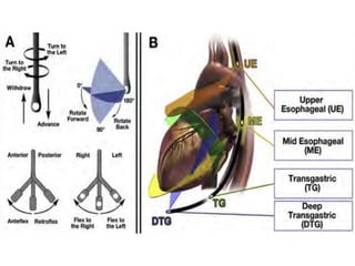
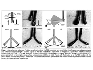
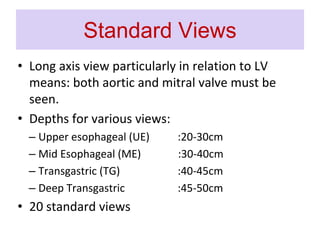
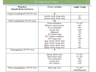
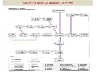
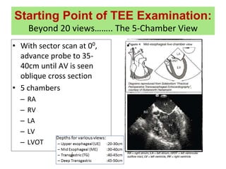
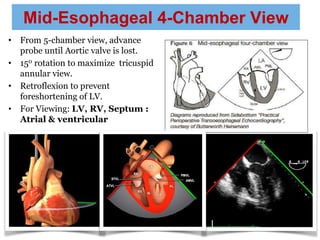
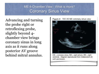
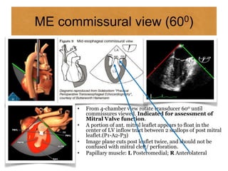
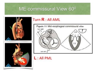
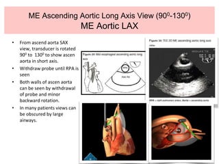
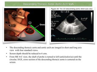
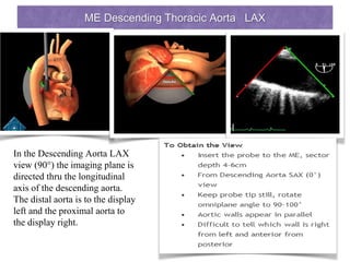
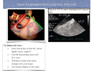
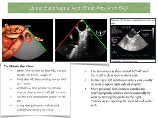
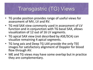
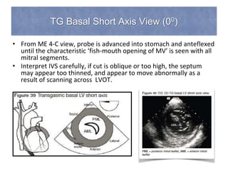
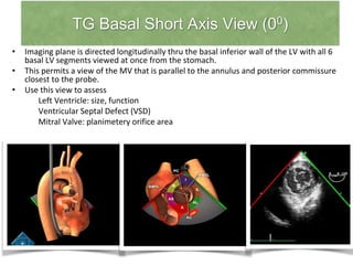
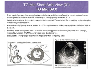
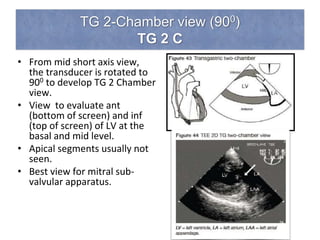
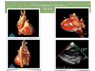
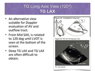
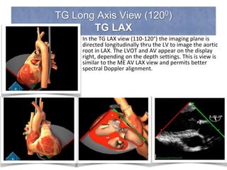
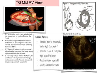
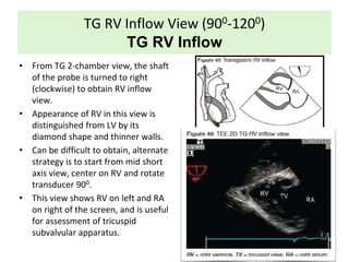
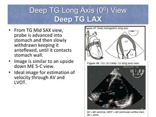
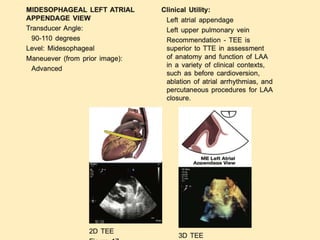
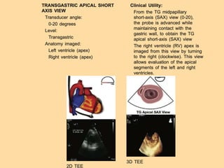
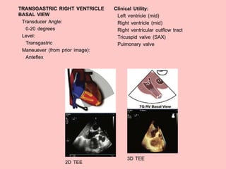
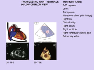
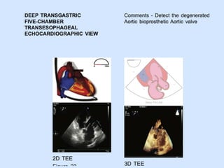
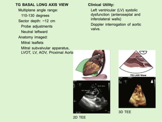
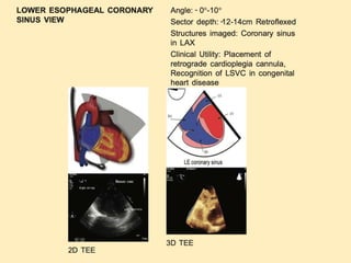
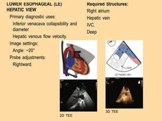
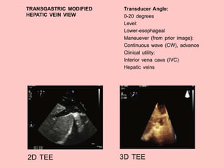
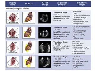
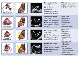
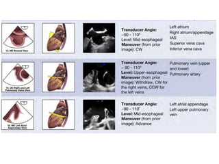
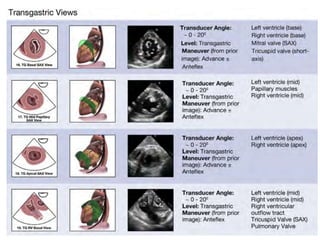
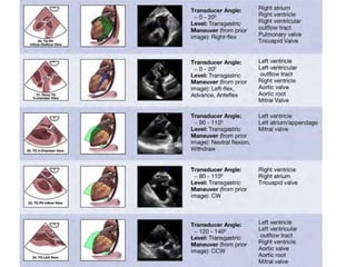
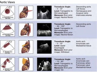
Comprehensive TEE
examination
PRESENTER: DR RICHA MALIK
MODERATOR: DR AJAY KUMAR
Advantages of TEE
- The advantage of TEE over TTE is usually clearer images,
especially of structures that are difficult to view transthoracically
(through the chest wall).
- the heart rests directly upon the esophagus leaving only
millimeters that the ultrasound beam has to travel. This reduces
the attenuation (weakening) of the ultrasound signal,
generating a stronger return signal, ultimately enhancing image
and Doppler quality.
Advantages of TEE
- Comparatively, transthoracic ultrasound must first traverse skin, fat, ribs and
lungs before reflecting off the heart and back to the probe before an image
can be created. All these structures, along with the increased distance the
beam must travel, weaken the ultrasound signal thus degrading the image
and Doppler quality.
- In adults, several structures can be evaluated and imaged better with the
TEE, including the aorta, pulmonary artery, valves of the heart, both atria,
atrial septum, left atrial appendage, and coronary arteries. TEE has a very
high sensitivity for locating a blood clot inside the left atrium.
INDICATIONS
CONTRAINDICATIONS
Probe preparation and placement
• Minimally invasive and complications are rare
provided care is taken and contraindications
avoided.
• GE hemorrhage and esophageal perforations are
rare but potentially fatal.
• Probes are modified gastroscopes and suitable
for use in patients heavier than 25 kg.
• Small probes are available for pediatric use.
Probe Insertion Techniques in OT
• In the operating room, the patient remains supine and probe
is typically placed from the head of the bed with slight
anteflexion of the probe.
• The bite block should not be placed in the mouth before
placement of the probe, because this will displace the tongue
posteriorly and obstruct probe passage.
• Lifting the mandible anteriorly and caudally usually opens the
mouth and displaces the tongue anteriorly to allow smooth
probe placement.
• A laryngoscope can be used to facilitate probe placement into
the esophagus, or the fingers can guide the probe into the
posterior fossa in anesthetized patients.
• Ensure the patient is deeply anesthetized or paralyzed before
inserting fingers into the oropharynx, as the bite block is not
present
Probe movement
Small wheel rotation
Left and right
Large wheel rotation
0-1800
Probe position and orientation
• Apex of sector scan
marking origin from
esophageal probe is shown
at the top and locates post
structures.
• Transverse image plane at
00, L of image is towards
patient’s R
Probe position and orientation
• In the vertical plane
image 900, L side of
image is inferior and
points towards patient’s
feet.
• Right side of image is
anterior and points
towards patient’s head.
Area of interest in the center
• Once a structure has been centered within one
image plane, it will remain in the center in
subsequent image planes as the transducer is
rotated between 0-180.
• This feature helps in 3-dimentional assessment
of the structure.
• To center the structure in a image:
– At 00, turn shaft Left or Right
– At 900, advance or withdraw shaft vertically
Systematic Examination
Standard Views
• Connect ECG.
• Adjust 2D gain to get chambers black and tissue
grey/white.
• Adjust colour gain .
• Start at sector depth of 12 cm that is
standardised to assess heart size: small, normal
or dilated.
• Rule of thumb: At TG view at 12 cm, LV should
fill up 2/3rd of the sector.
Standard Views
• Long axis view particularly in relation to LV
means: both aortic and mitral valve must be
seen.
• Depths for various views:
– Upper esophageal (UE) :20-30cm
– Mid Esophageal (ME) :30-40cm
– Transgastric (TG) :40-45cm
– Deep Transgastric :45-50cm
• 20 standard views
20 standard views
Scheme to obtain 20 Standard TEE views
Starting Point of TEE Examination:
Beyond 20 views…….. The 5-Chamber View
• With sector scan at 00,
advance probe to 35-
40cm until AV is seen
oblique cross section
• 5 chambers
– RA
– RV
– LA
– LV
– LVOT
• .
Mid-Esophageal 4-Chamber View
• From 5-chamber view, advance
probe until Aortic valve is lost.
• 150 rotation to maximize tricuspid
annular view.
• Retroflexion to prevent
foreshortening of LV.
• For Viewing: LV, RV, Septum :
Atrial & ventricular
ME 4-Chamber View : What is more?
Coronary Sinus View
Advancing and turning
the probe right or
retroflexing probe,
slightly beyond 4-
chamber view brings
coronary sinus in long
axis as it runs along
posterior AV groove
behind mitral annulus.
ME commissural view (600)
• From 4-chamber view rotate transducer 600 until
commissures viewed. Indicated for assessment of
Mitral Valve function.
• A portion of ant. mitral leaflet appears to float in the
center of LV inflow tract between 2 scallops of post mitral
leaflet.(P1-A2-P3)
• Image plane cuts post leaflet twice, and should not be
confused with mitral cleft/ perforation.
• Papillary muscle: L Posteromedial; R Anterolateral
ME commissural View 600
• Turn R : All AML
Turn L : All PML
Mid Esophageal 2-Chamber View 900
(ME 2C)
• From commissural
view, rotate 900,
until 2 chamber
view is seen.
• Useful for
assessment of LV
and MV.
• Identified by
appearance of
coronary sinus on L
and LA appendage
on R
Mid Esophageal 2-Chamber View 900
(ME 2C)
• In contrast to 4-C view, PML now appears
on L and AML on R adjacent to atrial
appendage.
• Inf wall is seen on L and ant wall on the R.
• If the LV appears to lengthen during
rotation of the transducer, it indicates
apex was not adequately visualized in 4-C
view.
• Clue to LV foreshortening  excessive
motion of apparent apex. When true apex
is visualized, wall motion and thickening
appear similar to surrounding myocardium
unless WMA present.
• Extension of apex below bottom of screen
in the 2-chamber view at 15cm depth
indicates LA/LV dilatation.
Midesophageal long-axis view
ME Long Axis View (1300)
ME AV LAX
• From AV short axis view,
transducer is rotated 90 deg-
130 deg to obtain long axis
view of AV. Probe is turned R
and L until leaflet excursion is
clear.
• RCC being most ant, is seen
lower most, adjacent to RVOT.
The cusp seen adjacent to AML
is either NCC(more often) or
LCC.
• If fluid has collected behind
heart, oblique pericardial sinus
may be seen between post wall
of LA and esophagus.
• Fluid in transverse pericardial
sinus is sometimes seen
between post wall of ascending
aorta and LA.
To Obtain the View ME AORTIC VALVE SHORT AXIS VIEW (45)
• Insert the probe to the ME, sector depth 8-l0cm.
. Find the ME 4C (0:) withdraw cephalad to obtain the ME 5C view (0:) that includes the LVOT and
AV.
. Rotate omniplane angle to 30- 45.
• Center aortic valve and aim to make 3 aortic valve cusps symmetric
• withdraw probe for coronary ostia . Advance probe for LVOT
ME RV inflow-outflow view (800)
• From ME 5-chamber view, rotate
transducer to 800 and turn
clockwise (R) to show TV and PV.
• Note RV free wall on L and RVOT
on the R.
• An in situ PAC can be seen to wrap
around AV from RA to TV to RVOT.
• This view provides good alignment
between a CW Doppler signal and
a jet of tricupid regurgitation.
• TV valve: Post leaflet on L
Ant leaflet on R
ME Ascending Aortic Short Axis View (400)
ME Aortic SAX
• From 5-chamber view, the
transducer is rotated between 00
to 400 and the probe is
withdrawn until short axis view
of ascending aorta is seen.
• The view shows proximal
ascending aorta, MPA, RPA and
SVC.
• Satisfactory alignment of Doppler
signal with blood flow through
MPA can be obtained.
• As the probe is progressively
withdrawn, MPA, initially seen as
circle becomes oval as it curves
posteriorly towards probe before
branching into R and L. At this
level, RPA separates probe from
aorta , and not LA.
ME Ascending Aortic Long Axis View (900-1300)
ME Aortic LAX
• From ascend aorta SAX
view, transducer is rotated
900 to 1300 to show ascen
aorta in short axis.
• Withdraw probe until RPA is
seen
• Both walls of ascen aorta
can be seen by withdrawal
of probe and minor
backward rotation.
• In many patients views can
be obscured by large
airways.
Descending Thoracic Aorta, Aortic Arch SAX
• The descending thoracic aorta and aortic arch are imaged in short and long axis
view with four standard views.
• Screen depth should be reduced to 6 cms.
• From ME 4-C view, the shaft of probe is turned to left (anticlockwise) until the
circular, SAX, cross section of the descending thoracic aorta is centered on the
screen.
ME Descending Thoracic Aorta LAX
In the Descending Aorta LAX
view (90°) the imaging plane is
directed thru the longitudinal
axis of the descending aorta.
The distal aorta is to the display
left and the proximal aorta to
the display right.
Upper Esophageal Arch Long Axis Arch LAX
Upper Esophageal Arch Short Axis Arch SAX
• The transducer is then rotated 600-900 until
the distal arch is seen in short axis.
• In this view left subclavian artery can usually
be seen in upper right side of display.
• More proximal left common carotid and
brachiocephalic arteries can occasionally be
seen by turning the probe to the right
(clockwise) to open up the view of mid aortic
arch.
Transgastric (TG) Views
• TG probe position provides range of useful views for
assessment of MV, LV and RV.
• TG mid SAX view commonly used in assessment of LV
function and in conjunction with TG basal SAX, allows
visualization of 12 out of 16 LV segments.
• TG apical SAX view (not described by ASE/SCA) can
visualize remaining 4 apical segments.
• TG long axis and Deep TG LAX provide the only TEE
images for satisfactory alignment of Doppler for blood
flow through AV.
• ME and TG views may have some overlap but in practice
they are complementary.
TG Basal Short Axis View (00)
• From ME 4-C view, probe is advanced into stomach and anteflexed
until the characteristic ‘fish-mouth opening of MV’ is seen with all
mitral segments.
• Interpret IVS carefully, if cut is oblique or too high, the septum
may appear too thinned, and appear to move abnormally as a
result of scanning across LVOT.
TG Basal Short Axis View (00)
• Imaging plane is directed longitudinally thru the basal inferior wall of the LV with all 6
basal LV segments viewed at once from the stomach.
• This permits a view of the MV that is parallel to the annulus and posterior commissure
closest to the probe.
• Use this view to assess
Left Ventricle: size, function
Ventricular Septal Defect (VSD)
Mitral Valve: planimetery orifice area
TG Mid Short Axis View (00)
TG Mid SAX
• From basal short axis view, probe is advanced slightly, and then anteflexed to keep it apposed to the
diaphragmatic surface of stomach to develop TG mid-papillary short axis of LV.
• Gentle adjustment of flexion with forward rotation up to 150 may be helpful in avoiding oblique imaging
indicated by oval shaped LV.
• Posteromedial papillary muscle is seen at 1 o’clock position and anterolateral papillary muscle is seen at
5 o’clock.
• Probably most widely used view , useful for monitoring global LV function (fractional area change),
regional LV function (RWMA), and preload (end-diastolic area) .
• Best used by saving ‘loops’ at different stages and then comparing later.
TG 2-Chamber view (900)
TG 2 C
• From mid short axis view,
the transducer is rotated to
900 to develop TG 2 Chamber
view.
• View to evaluate ant
(bottom of screen) and inf
(top of screen) of LV at the
basal and mid level.
• Apical segments usually not
seen.
• Best view for mitral sub-
valvular apparatus.
TG 2-Chamber view (900)
TG 2 C
TG Long Axis View (1200)
TG LAX
• An alternative view
suitable for Doppler
evaluation of AV and
outflow tract.
• From Mid SAX, is rotated
to 120 deg until LVOT is
seen at the bottom of the
screen.
• Deep TG LAX and TG LAX
are often difficult to
obtain.
TG Long Axis View (1200)
TG LAX
In the TG LAX view (110-120°) the imaging plane is
directed longitudinally thru the LV to image the aortic
root in LAX. The LVOT and AV appear on the display
right, depending on the depth settings. This is view is
similar to the ME AV LAX view and permits better
spectral Doppler alignment.
TG Mid RV View
• By turning the probe right (clockwise),
the image may be centered on the RV
SAX.
• Crescentic shape and more extensive
trabeculae of RV compared to LV are
evident. RV wall thickness is normally
half that of LV.
• RV free wall has no formal segmental
classification but terms like basal, apical,
anterior and inferior are used.
• RV usually not cut in true short axis, this
combined with asymmetric RV shape,
makes assessment of chamber size and
thickness potentially unreliable.
TG RV Inflow View (900-1200)
TG RV Inflow
• From TG 2-chamber view, the shaft
of the probe is turned to right
(clockwise) to obtain RV inflow
view.
• Appearance of RV in this view is
distinguished from LV by its
diamond shape and thinner walls.
• Can be difficult to obtain, alternate
strategy is to start from mid short
axis view, center on RV and rotate
transducer 900.
• This view shows RV on left and RA
on right of the screen, and is useful
for assessment of tricuspid
subvalvular apparatus.
Deep TG Long Axis (00) View
Deep TG LAX
• From TG Mid SAX view,
probe is advanced into
stomach and then slowly
withdrawn keeping it
anteflexed, until it contacts
stomach wall.
• Image is similar to an upside
down ME 5-C view.
• Ideal image for estimation of
velocity through AV and
LVOT.
Deep TG Long Axis (00) View
Deep TG LAX
Use this View to
– Diagnose paravalvular leak prosthetic aortic valve
– AV gradient spectral doppler
– LVOT gradient spectral doppler
Mitral Valve
Views and Key Structures
Aortic Valve
Left Ventricle
Views and Key Structures
Interatrial Septum and Venae Cavae
Descending Thoracic Aorta
Ascending Aorta and Pulmonary Artery
ttT

comprehensive TEE examination

  • 1.
    Comprehensive TEE examination PRESENTER: DRRICHA MALIK MODERATOR: DR AJAY KUMAR
  • 2.
    Advantages of TEE -The advantage of TEE over TTE is usually clearer images, especially of structures that are difficult to view transthoracically (through the chest wall). - the heart rests directly upon the esophagus leaving only millimeters that the ultrasound beam has to travel. This reduces the attenuation (weakening) of the ultrasound signal, generating a stronger return signal, ultimately enhancing image and Doppler quality.
  • 3.
    Advantages of TEE -Comparatively, transthoracic ultrasound must first traverse skin, fat, ribs and lungs before reflecting off the heart and back to the probe before an image can be created. All these structures, along with the increased distance the beam must travel, weaken the ultrasound signal thus degrading the image and Doppler quality. - In adults, several structures can be evaluated and imaged better with the TEE, including the aorta, pulmonary artery, valves of the heart, both atria, atrial septum, left atrial appendage, and coronary arteries. TEE has a very high sensitivity for locating a blood clot inside the left atrium.
  • 4.
  • 5.
  • 6.
    Probe preparation andplacement • Minimally invasive and complications are rare provided care is taken and contraindications avoided. • GE hemorrhage and esophageal perforations are rare but potentially fatal. • Probes are modified gastroscopes and suitable for use in patients heavier than 25 kg. • Small probes are available for pediatric use.
  • 7.
    Probe Insertion Techniquesin OT • In the operating room, the patient remains supine and probe is typically placed from the head of the bed with slight anteflexion of the probe. • The bite block should not be placed in the mouth before placement of the probe, because this will displace the tongue posteriorly and obstruct probe passage. • Lifting the mandible anteriorly and caudally usually opens the mouth and displaces the tongue anteriorly to allow smooth probe placement. • A laryngoscope can be used to facilitate probe placement into the esophagus, or the fingers can guide the probe into the posterior fossa in anesthetized patients. • Ensure the patient is deeply anesthetized or paralyzed before inserting fingers into the oropharynx, as the bite block is not present
  • 8.
    Probe movement Small wheelrotation Left and right Large wheel rotation 0-1800
  • 11.
    Probe position andorientation • Apex of sector scan marking origin from esophageal probe is shown at the top and locates post structures. • Transverse image plane at 00, L of image is towards patient’s R
  • 12.
    Probe position andorientation • In the vertical plane image 900, L side of image is inferior and points towards patient’s feet. • Right side of image is anterior and points towards patient’s head.
  • 13.
    Area of interestin the center • Once a structure has been centered within one image plane, it will remain in the center in subsequent image planes as the transducer is rotated between 0-180. • This feature helps in 3-dimentional assessment of the structure. • To center the structure in a image: – At 00, turn shaft Left or Right – At 900, advance or withdraw shaft vertically
  • 14.
    Systematic Examination Standard Views •Connect ECG. • Adjust 2D gain to get chambers black and tissue grey/white. • Adjust colour gain . • Start at sector depth of 12 cm that is standardised to assess heart size: small, normal or dilated. • Rule of thumb: At TG view at 12 cm, LV should fill up 2/3rd of the sector.
  • 17.
    Standard Views • Longaxis view particularly in relation to LV means: both aortic and mitral valve must be seen. • Depths for various views: – Upper esophageal (UE) :20-30cm – Mid Esophageal (ME) :30-40cm – Transgastric (TG) :40-45cm – Deep Transgastric :45-50cm • 20 standard views
  • 18.
  • 19.
    Scheme to obtain20 Standard TEE views
  • 20.
    Starting Point ofTEE Examination: Beyond 20 views…….. The 5-Chamber View • With sector scan at 00, advance probe to 35- 40cm until AV is seen oblique cross section • 5 chambers – RA – RV – LA – LV – LVOT • .
  • 21.
    Mid-Esophageal 4-Chamber View •From 5-chamber view, advance probe until Aortic valve is lost. • 150 rotation to maximize tricuspid annular view. • Retroflexion to prevent foreshortening of LV. • For Viewing: LV, RV, Septum : Atrial & ventricular
  • 22.
    ME 4-Chamber View: What is more? Coronary Sinus View Advancing and turning the probe right or retroflexing probe, slightly beyond 4- chamber view brings coronary sinus in long axis as it runs along posterior AV groove behind mitral annulus.
  • 23.
    ME commissural view(600) • From 4-chamber view rotate transducer 600 until commissures viewed. Indicated for assessment of Mitral Valve function. • A portion of ant. mitral leaflet appears to float in the center of LV inflow tract between 2 scallops of post mitral leaflet.(P1-A2-P3) • Image plane cuts post leaflet twice, and should not be confused with mitral cleft/ perforation. • Papillary muscle: L Posteromedial; R Anterolateral
  • 24.
    ME commissural View600 • Turn R : All AML Turn L : All PML
  • 25.
    Mid Esophageal 2-ChamberView 900 (ME 2C) • From commissural view, rotate 900, until 2 chamber view is seen. • Useful for assessment of LV and MV. • Identified by appearance of coronary sinus on L and LA appendage on R
  • 26.
    Mid Esophageal 2-ChamberView 900 (ME 2C) • In contrast to 4-C view, PML now appears on L and AML on R adjacent to atrial appendage. • Inf wall is seen on L and ant wall on the R. • If the LV appears to lengthen during rotation of the transducer, it indicates apex was not adequately visualized in 4-C view. • Clue to LV foreshortening  excessive motion of apparent apex. When true apex is visualized, wall motion and thickening appear similar to surrounding myocardium unless WMA present. • Extension of apex below bottom of screen in the 2-chamber view at 15cm depth indicates LA/LV dilatation.
  • 28.
  • 29.
    ME Long AxisView (1300) ME AV LAX • From AV short axis view, transducer is rotated 90 deg- 130 deg to obtain long axis view of AV. Probe is turned R and L until leaflet excursion is clear. • RCC being most ant, is seen lower most, adjacent to RVOT. The cusp seen adjacent to AML is either NCC(more often) or LCC. • If fluid has collected behind heart, oblique pericardial sinus may be seen between post wall of LA and esophagus. • Fluid in transverse pericardial sinus is sometimes seen between post wall of ascending aorta and LA.
  • 30.
    To Obtain theView ME AORTIC VALVE SHORT AXIS VIEW (45) • Insert the probe to the ME, sector depth 8-l0cm. . Find the ME 4C (0:) withdraw cephalad to obtain the ME 5C view (0:) that includes the LVOT and AV. . Rotate omniplane angle to 30- 45. • Center aortic valve and aim to make 3 aortic valve cusps symmetric • withdraw probe for coronary ostia . Advance probe for LVOT
  • 31.
    ME RV inflow-outflowview (800) • From ME 5-chamber view, rotate transducer to 800 and turn clockwise (R) to show TV and PV. • Note RV free wall on L and RVOT on the R. • An in situ PAC can be seen to wrap around AV from RA to TV to RVOT. • This view provides good alignment between a CW Doppler signal and a jet of tricupid regurgitation. • TV valve: Post leaflet on L Ant leaflet on R
  • 32.
    ME Ascending AorticShort Axis View (400) ME Aortic SAX • From 5-chamber view, the transducer is rotated between 00 to 400 and the probe is withdrawn until short axis view of ascending aorta is seen. • The view shows proximal ascending aorta, MPA, RPA and SVC. • Satisfactory alignment of Doppler signal with blood flow through MPA can be obtained. • As the probe is progressively withdrawn, MPA, initially seen as circle becomes oval as it curves posteriorly towards probe before branching into R and L. At this level, RPA separates probe from aorta , and not LA.
  • 33.
    ME Ascending AorticLong Axis View (900-1300) ME Aortic LAX • From ascend aorta SAX view, transducer is rotated 900 to 1300 to show ascen aorta in short axis. • Withdraw probe until RPA is seen • Both walls of ascen aorta can be seen by withdrawal of probe and minor backward rotation. • In many patients views can be obscured by large airways.
  • 34.
    Descending Thoracic Aorta,Aortic Arch SAX • The descending thoracic aorta and aortic arch are imaged in short and long axis view with four standard views. • Screen depth should be reduced to 6 cms. • From ME 4-C view, the shaft of probe is turned to left (anticlockwise) until the circular, SAX, cross section of the descending thoracic aorta is centered on the screen.
  • 35.
    ME Descending ThoracicAorta LAX In the Descending Aorta LAX view (90°) the imaging plane is directed thru the longitudinal axis of the descending aorta. The distal aorta is to the display left and the proximal aorta to the display right.
  • 36.
    Upper Esophageal ArchLong Axis Arch LAX
  • 37.
    Upper Esophageal ArchShort Axis Arch SAX • The transducer is then rotated 600-900 until the distal arch is seen in short axis. • In this view left subclavian artery can usually be seen in upper right side of display. • More proximal left common carotid and brachiocephalic arteries can occasionally be seen by turning the probe to the right (clockwise) to open up the view of mid aortic arch.
  • 38.
    Transgastric (TG) Views •TG probe position provides range of useful views for assessment of MV, LV and RV. • TG mid SAX view commonly used in assessment of LV function and in conjunction with TG basal SAX, allows visualization of 12 out of 16 LV segments. • TG apical SAX view (not described by ASE/SCA) can visualize remaining 4 apical segments. • TG long axis and Deep TG LAX provide the only TEE images for satisfactory alignment of Doppler for blood flow through AV. • ME and TG views may have some overlap but in practice they are complementary.
  • 39.
    TG Basal ShortAxis View (00) • From ME 4-C view, probe is advanced into stomach and anteflexed until the characteristic ‘fish-mouth opening of MV’ is seen with all mitral segments. • Interpret IVS carefully, if cut is oblique or too high, the septum may appear too thinned, and appear to move abnormally as a result of scanning across LVOT.
  • 40.
    TG Basal ShortAxis View (00) • Imaging plane is directed longitudinally thru the basal inferior wall of the LV with all 6 basal LV segments viewed at once from the stomach. • This permits a view of the MV that is parallel to the annulus and posterior commissure closest to the probe. • Use this view to assess Left Ventricle: size, function Ventricular Septal Defect (VSD) Mitral Valve: planimetery orifice area
  • 41.
    TG Mid ShortAxis View (00) TG Mid SAX • From basal short axis view, probe is advanced slightly, and then anteflexed to keep it apposed to the diaphragmatic surface of stomach to develop TG mid-papillary short axis of LV. • Gentle adjustment of flexion with forward rotation up to 150 may be helpful in avoiding oblique imaging indicated by oval shaped LV. • Posteromedial papillary muscle is seen at 1 o’clock position and anterolateral papillary muscle is seen at 5 o’clock. • Probably most widely used view , useful for monitoring global LV function (fractional area change), regional LV function (RWMA), and preload (end-diastolic area) . • Best used by saving ‘loops’ at different stages and then comparing later.
  • 42.
    TG 2-Chamber view(900) TG 2 C • From mid short axis view, the transducer is rotated to 900 to develop TG 2 Chamber view. • View to evaluate ant (bottom of screen) and inf (top of screen) of LV at the basal and mid level. • Apical segments usually not seen. • Best view for mitral sub- valvular apparatus.
  • 43.
    TG 2-Chamber view(900) TG 2 C
  • 44.
    TG Long AxisView (1200) TG LAX • An alternative view suitable for Doppler evaluation of AV and outflow tract. • From Mid SAX, is rotated to 120 deg until LVOT is seen at the bottom of the screen. • Deep TG LAX and TG LAX are often difficult to obtain.
  • 45.
    TG Long AxisView (1200) TG LAX In the TG LAX view (110-120°) the imaging plane is directed longitudinally thru the LV to image the aortic root in LAX. The LVOT and AV appear on the display right, depending on the depth settings. This is view is similar to the ME AV LAX view and permits better spectral Doppler alignment.
  • 46.
    TG Mid RVView • By turning the probe right (clockwise), the image may be centered on the RV SAX. • Crescentic shape and more extensive trabeculae of RV compared to LV are evident. RV wall thickness is normally half that of LV. • RV free wall has no formal segmental classification but terms like basal, apical, anterior and inferior are used. • RV usually not cut in true short axis, this combined with asymmetric RV shape, makes assessment of chamber size and thickness potentially unreliable.
  • 47.
    TG RV InflowView (900-1200) TG RV Inflow • From TG 2-chamber view, the shaft of the probe is turned to right (clockwise) to obtain RV inflow view. • Appearance of RV in this view is distinguished from LV by its diamond shape and thinner walls. • Can be difficult to obtain, alternate strategy is to start from mid short axis view, center on RV and rotate transducer 900. • This view shows RV on left and RA on right of the screen, and is useful for assessment of tricuspid subvalvular apparatus.
  • 48.
    Deep TG LongAxis (00) View Deep TG LAX • From TG Mid SAX view, probe is advanced into stomach and then slowly withdrawn keeping it anteflexed, until it contacts stomach wall. • Image is similar to an upside down ME 5-C view. • Ideal image for estimation of velocity through AV and LVOT.
  • 49.
    Deep TG LongAxis (00) View Deep TG LAX Use this View to – Diagnose paravalvular leak prosthetic aortic valve – AV gradient spectral doppler – LVOT gradient spectral doppler
  • 50.
    Mitral Valve Views andKey Structures
  • 51.
  • 52.
  • 53.
  • 54.
  • 55.
    Ascending Aorta andPulmonary Artery
  • 72.