Easy testing for smps led driver
•Download as PPTX, PDF•
0 likes•1,377 views

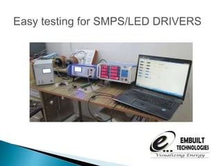
This system makes LED Driver, SMPS Testing easy, faster and organized. This test devices on user specified voltages and makes report.
Report
Share
Report
Share

Recommended
Plc analog Tutorial
This document discusses analog inputs and outputs for programmable logic controllers (PLCs). It begins by introducing analog values as continuous rather than discrete, and how they must be converted to and from digital values using analog-to-digital (A/D) and digital-to-analog (D/A) converters. It then focuses on the principles of analog inputs, including sampling issues like aliasing and quantization error. Equations are provided to calculate values from A/D converters. The document also briefly discusses analog outputs and the relationships for D/A conversion.
Ec8791 lpc2148 timer unit
LPC 2148 Timer Unit- Registers associated with LPC 2148 Timer, How to program LPC 2148 Timer/Counter/ECE/ 7Sem/ EC8791/ERTS
Analog To Digital Conversion (ADC) Programming in LPC2148
1) The document describes programming the on-chip 10-bit ADC of the LPC2148 microcontroller to implement a simple data acquisition system. It discusses the features of the ADC, the programming interface, control registers, and provides code to initialize the ADC and read conversion results.
2) The code configures the ADC ports and control registers, reads the conversion results when the ADC status indicates a conversion is complete, and prints the voltage levels to the UART.
3) The results show the ADC accurately converts analog voltages from 0-3.1V to their corresponding 10-bit digital values, which are printed to the UART terminal.
Ec8791 lpc2148 pwm
This document discusses pulse width modulation (PWM) and how it is implemented on the LPC2148 microcontroller. PWM is a technique for controlling the power delivered to a load by varying the duty cycle, or on-time, of a pulse signal while keeping frequency constant. The LPC2148 has a 32-bit timer/counter for PWM that can generate either single-edge or double-edge controlled PWM signals on multiple pins. It uses match registers to set the PWM period and pulse widths by controlling the rising and/or falling edges of the output pulses.
Part 5 PLC inputs & outputs
There are two main types of input/output modules for a PLC: analog and digital. Analog modules handle continuous signals like 0-10V, 4-20mA, and -20-20mA, while digital modules handle on/off signals represented as 1s and 0s. Common digital inputs include push buttons, switches, and sensors, while common digital outputs include relays, contactors, and lamps. Analog inputs include temperature and pressure sensors, and analog outputs control actuators, valves, and drives. The next video will discuss PLC programming languages.
Part 8 PLC faundamentals of wiring sink and source
Hello Friends,
in this video i have Discuss PLC Fundamental Wirnig and also we learn Sink and Source.
8253
The MSM82C53-2 is a CMOS programmable interval timer that contains three independent 16-bit counters. It can be programmed to operate in six different counter modes and count in binary or BCD. The device is controlled through programming of a control word register that selects the operating mode and count format for each counter. Count values are then loaded into the counters according to the programmed read/load format. The device outputs the counter states and is interfaced to a microprocessor through an address bus, data bus, and control signals.
Presentation industrial control
A multi-disciplinary control process of industrial plant. It is a group project designed by Subarna, Zheng and Liu.
Industrial Temperature Controller using Microcontroller
This practical temperature controller controls the temperature of any device according to its requirement for any industrial application. It also displays the temperature on an LCD displays in the range of –55°C to +125°C. At the heart of the circuit is the microcontroller from 8051 family which controls all its functions. It is important to control the speed of DC motor where precision and protection are essence. Here we will use a technique called PWM (pulse width modulation) to control the speed of DC motor.
PLC
This document is an introduction to the subject of mechatronics presented by Ramakant Rana. It provides various examples of circuits and programs used in mechatronics applications, including diagrams of PLC architecture, opto-isolators, ladder logic, timers, counters, shift registers, and proportional control examples. Contact information is provided to access further materials on the topics covered.
Pwm(Pulse Width Modulation) presentation
The Modulation technique to control steady actions like DC motors in Embedded Systems. the fastness and slowness of the speed is not swiftly rich at peak state, so this is done by PWM
8253
The 8253/8254 timer contains three independent counters that can each divide the input clock frequency. It has four I/O port addresses to access the individual counters and the control register. Each counter has pins for the clock input, output, and gating signal. The timer can operate in different modes like interrupt on terminal count, one shot, rate generator, and software/hardware triggered strobe by programming the corresponding counter and control registers.
Part 11 How to use binary concept In PLC.
Part 11 How to use binary concept In PLC.
hello Friend
I this video we learn about of how to use logic gates in PLC programming.
8254 presentation
The document discusses the Intel 8254 programmable interval timer/counter chip. It provides three independent 16-bit counters that can generate timing signals and time delays under software control. The 8254 has applications in real-time clocks, event counters, waveform generation and motor control. It interfaces with microprocessors through control and data lines. Counters are programmed by writing control words and initial counts, and can be read through simple reads, latching commands, or status read-back commands.
Temperature Controller with Atmega16
This document describes the design and implementation of a temperature controller using an FPGA, microcontroller, and NE555 timer chip. It acknowledges the project guidance provided. Diagrams of the working model, definitions, flowcharts and block diagrams are presented to explain the temperature sensing, analog to digital conversion, PWM signal generation, and output control. Details are given on the hardware components used including the LM35 temperature sensor, Atmega16 microcontroller, LCD display, and NE555 timer chip. The operation and limitations of the temperature controller system are also summarized.
speed control of induction motor using plc and vfd
This document discusses speed control of an induction motor using a PLC. It describes the main components involved, including a variable frequency drive, switched mode power supply, and PLC. It also provides information on ladder logic programming and the basic signal flow within a PLC system from sensor inputs to motor outputs.
8254 Programmable Interval Timer by vijay
The 8254 Programmable Interval Timer is an integrated circuit that provides three independent programmable timers/counters that can count at rates from DC to 10 MHz. It has various operating modes like interrupt on terminal count, programmable monoshot, rate generator, square wave generator, and software/hardware triggered strobe. The document discusses the architecture, components, modes of operation, and read operations of the 8254 timer chip in detail.
SEM88_Presentation
The document describes the SEM88 8-Port Serial Switch device. It has 8 serial ports that support different baud rates, parity, and character lengths to connect up to 8 devices. It also supports connecting two environmental sensors to monitor temperature and humidity. The device uses ARM technology and has Ethernet, USB, RS-232, and serial interfaces to manage the connected devices and sensors.
Packaging & Textile Temperature Controller, MAXVU
Introducing the innovative new temperature controller, MAXVU from West Control Solutions.
The MAXVU controller offers fast, reliable temperature control for packaging, textile and food and beverage machine builders on a budget.
MAXVU provides an uniquely large display, clearly visible from a distance and with a wide viewing angle.
The temperature controller has an extremely simple, easy-to-use set up menu, which concentrates on the essential parameters, meaning the controller can be set up in under 60 seconds for most common applications.
Programmable Timer 8253/8254
8253 Programmable Interval Timer IC. Basic descriptions, Internal block diagrams, Modes of operation and command words are included
Automatic temperature control
This document describes an automatic temperature control system using an 8085 microprocessor. The system uses an AD590 temperature sensor, differential amplifier, ADC0808 converter, and 8085 microprocessor to monitor and control the temperature. It aims to minimize manual intervention and control temperature in industrial plants. The system works by comparing the measured temperature to upper and lower setpoints and turning the heater or cooler on/off accordingly to maintain the temperature within the limits.
Digitalinputsoutputs
Digital inputs and outputs can be controlled through various logic priorities. The highest priority is direct control, followed by demand, timer, and time-of-use controls. Outputs default to an always-on state, and the control logics determine when to turn them off. Inputs can be configured for different functions like event monitoring, pulse counting, or interfacing with energy meters. Both inputs and outputs can be inverted, filtered, or controlled through timers and other functions.
Digital inputs & outputs
The document discusses digital inputs and outputs for control systems. It explains that by default outputs are always on, and control logic is used to turn outputs off based on priorities. It also describes how outputs can be controlled by different logics like demand, timer, and time of use according to a specified priority order. Advanced control functions include timers, minimum on/off times, and pause times. Digital inputs interface physical devices and can be configured for different types of operation like counting or detecting state changes. Inputs can be used individually or combined to interface with energy meters and pulses.
8051
The Intel MCS-51 (commonly referred to as 8051) is a Harvard architecture, CISC instruction set, single chip microcontroller (µC) series which was developed by Intel in 1980 for use in embedded systems.[1] Intel's original versions were popular in the 1980s and early 1990s and enhanced binary compatible derivatives remain popular today.
Lec 12 (cont plc)
This document discusses different types and programming of timers in PLC systems. It describes common approaches to modeling timers as relays or delay blocks. There are different types of timers including on-delay, off-delay, and pulse timers. Programming of timers varies between PLC manufacturers, with some treating timers as coils and others as delays. Examples are provided for sequencing motors using timers, cascading timers, producing an on-off cycle, and flashing a light using timers.
8254 timer - Microprocessor and interfacing
The 8254 timer has 3 independent 16-bit counters that can be programmed to operate in 6 different modes, including generating interrupts, oneshots, square waves, and strobes. Each counter is controlled by a programmable word and clock input, and can count in binary or BCD. The 8254 provides improved frequency operation over the 8253, up to 10 MHz.
8253ppt
The 8253 is a programmable timer/counter chip used in Intel microcomputers. It has 3 counters and 6 programmable modes. The modes determine how the OUT signal behaves, such as pulsing low/high periodically or non-periodically. The control byte programs the counter selection, read/write mode, count mode, and binary/BCD selection. Common uses include creating time intervals and counting events.
Gesmod
The document describes the Gesmod management and control system for a transmitter. Gesmod provides centralized supervision and control, interfaces between system components, and implements encoding algorithms. It contains several electronic boards including an SBC computer board, digital I/O boards, an MMI interface, and boards for safety devices, measurements, blocking functions, and encoding. Gesmod processes inputs, generates control signals, and monitors the transmitter system.
pH/redox Transmitter
Mycom S CPM153 with controller and limit value functions for Ex and non-Ex areas. Email: lam.nguyen@vietan-enviro.com HP: 0945 293292
Machine monitoring system
MACHINE MONITORING SYSTEM (DM-2000)
Bently 3300 monitoring system
TDIX
DM 2000 details
LATEST ASSETS MANAGEMENT SYSTEM (SYSTEM-1 )
More Related Content
What's hot
Industrial Temperature Controller using Microcontroller
This practical temperature controller controls the temperature of any device according to its requirement for any industrial application. It also displays the temperature on an LCD displays in the range of –55°C to +125°C. At the heart of the circuit is the microcontroller from 8051 family which controls all its functions. It is important to control the speed of DC motor where precision and protection are essence. Here we will use a technique called PWM (pulse width modulation) to control the speed of DC motor.
PLC
This document is an introduction to the subject of mechatronics presented by Ramakant Rana. It provides various examples of circuits and programs used in mechatronics applications, including diagrams of PLC architecture, opto-isolators, ladder logic, timers, counters, shift registers, and proportional control examples. Contact information is provided to access further materials on the topics covered.
Pwm(Pulse Width Modulation) presentation
The Modulation technique to control steady actions like DC motors in Embedded Systems. the fastness and slowness of the speed is not swiftly rich at peak state, so this is done by PWM
8253
The 8253/8254 timer contains three independent counters that can each divide the input clock frequency. It has four I/O port addresses to access the individual counters and the control register. Each counter has pins for the clock input, output, and gating signal. The timer can operate in different modes like interrupt on terminal count, one shot, rate generator, and software/hardware triggered strobe by programming the corresponding counter and control registers.
Part 11 How to use binary concept In PLC.
Part 11 How to use binary concept In PLC.
hello Friend
I this video we learn about of how to use logic gates in PLC programming.
8254 presentation
The document discusses the Intel 8254 programmable interval timer/counter chip. It provides three independent 16-bit counters that can generate timing signals and time delays under software control. The 8254 has applications in real-time clocks, event counters, waveform generation and motor control. It interfaces with microprocessors through control and data lines. Counters are programmed by writing control words and initial counts, and can be read through simple reads, latching commands, or status read-back commands.
Temperature Controller with Atmega16
This document describes the design and implementation of a temperature controller using an FPGA, microcontroller, and NE555 timer chip. It acknowledges the project guidance provided. Diagrams of the working model, definitions, flowcharts and block diagrams are presented to explain the temperature sensing, analog to digital conversion, PWM signal generation, and output control. Details are given on the hardware components used including the LM35 temperature sensor, Atmega16 microcontroller, LCD display, and NE555 timer chip. The operation and limitations of the temperature controller system are also summarized.
speed control of induction motor using plc and vfd
This document discusses speed control of an induction motor using a PLC. It describes the main components involved, including a variable frequency drive, switched mode power supply, and PLC. It also provides information on ladder logic programming and the basic signal flow within a PLC system from sensor inputs to motor outputs.
8254 Programmable Interval Timer by vijay
The 8254 Programmable Interval Timer is an integrated circuit that provides three independent programmable timers/counters that can count at rates from DC to 10 MHz. It has various operating modes like interrupt on terminal count, programmable monoshot, rate generator, square wave generator, and software/hardware triggered strobe. The document discusses the architecture, components, modes of operation, and read operations of the 8254 timer chip in detail.
SEM88_Presentation
The document describes the SEM88 8-Port Serial Switch device. It has 8 serial ports that support different baud rates, parity, and character lengths to connect up to 8 devices. It also supports connecting two environmental sensors to monitor temperature and humidity. The device uses ARM technology and has Ethernet, USB, RS-232, and serial interfaces to manage the connected devices and sensors.
Packaging & Textile Temperature Controller, MAXVU
Introducing the innovative new temperature controller, MAXVU from West Control Solutions.
The MAXVU controller offers fast, reliable temperature control for packaging, textile and food and beverage machine builders on a budget.
MAXVU provides an uniquely large display, clearly visible from a distance and with a wide viewing angle.
The temperature controller has an extremely simple, easy-to-use set up menu, which concentrates on the essential parameters, meaning the controller can be set up in under 60 seconds for most common applications.
Programmable Timer 8253/8254
8253 Programmable Interval Timer IC. Basic descriptions, Internal block diagrams, Modes of operation and command words are included
Automatic temperature control
This document describes an automatic temperature control system using an 8085 microprocessor. The system uses an AD590 temperature sensor, differential amplifier, ADC0808 converter, and 8085 microprocessor to monitor and control the temperature. It aims to minimize manual intervention and control temperature in industrial plants. The system works by comparing the measured temperature to upper and lower setpoints and turning the heater or cooler on/off accordingly to maintain the temperature within the limits.
Digitalinputsoutputs
Digital inputs and outputs can be controlled through various logic priorities. The highest priority is direct control, followed by demand, timer, and time-of-use controls. Outputs default to an always-on state, and the control logics determine when to turn them off. Inputs can be configured for different functions like event monitoring, pulse counting, or interfacing with energy meters. Both inputs and outputs can be inverted, filtered, or controlled through timers and other functions.
Digital inputs & outputs
The document discusses digital inputs and outputs for control systems. It explains that by default outputs are always on, and control logic is used to turn outputs off based on priorities. It also describes how outputs can be controlled by different logics like demand, timer, and time of use according to a specified priority order. Advanced control functions include timers, minimum on/off times, and pause times. Digital inputs interface physical devices and can be configured for different types of operation like counting or detecting state changes. Inputs can be used individually or combined to interface with energy meters and pulses.
8051
The Intel MCS-51 (commonly referred to as 8051) is a Harvard architecture, CISC instruction set, single chip microcontroller (µC) series which was developed by Intel in 1980 for use in embedded systems.[1] Intel's original versions were popular in the 1980s and early 1990s and enhanced binary compatible derivatives remain popular today.
Lec 12 (cont plc)
This document discusses different types and programming of timers in PLC systems. It describes common approaches to modeling timers as relays or delay blocks. There are different types of timers including on-delay, off-delay, and pulse timers. Programming of timers varies between PLC manufacturers, with some treating timers as coils and others as delays. Examples are provided for sequencing motors using timers, cascading timers, producing an on-off cycle, and flashing a light using timers.
8254 timer - Microprocessor and interfacing
The 8254 timer has 3 independent 16-bit counters that can be programmed to operate in 6 different modes, including generating interrupts, oneshots, square waves, and strobes. Each counter is controlled by a programmable word and clock input, and can count in binary or BCD. The 8254 provides improved frequency operation over the 8253, up to 10 MHz.
8253ppt
The 8253 is a programmable timer/counter chip used in Intel microcomputers. It has 3 counters and 6 programmable modes. The modes determine how the OUT signal behaves, such as pulsing low/high periodically or non-periodically. The control byte programs the counter selection, read/write mode, count mode, and binary/BCD selection. Common uses include creating time intervals and counting events.
Gesmod
The document describes the Gesmod management and control system for a transmitter. Gesmod provides centralized supervision and control, interfaces between system components, and implements encoding algorithms. It contains several electronic boards including an SBC computer board, digital I/O boards, an MMI interface, and boards for safety devices, measurements, blocking functions, and encoding. Gesmod processes inputs, generates control signals, and monitors the transmitter system.
What's hot (20)
Industrial Temperature Controller using Microcontroller
Industrial Temperature Controller using Microcontroller
speed control of induction motor using plc and vfd
speed control of induction motor using plc and vfd
Similar to Easy testing for smps led driver
pH/redox Transmitter
Mycom S CPM153 with controller and limit value functions for Ex and non-Ex areas. Email: lam.nguyen@vietan-enviro.com HP: 0945 293292
Machine monitoring system
MACHINE MONITORING SYSTEM (DM-2000)
Bently 3300 monitoring system
TDIX
DM 2000 details
LATEST ASSETS MANAGEMENT SYSTEM (SYSTEM-1 )
What Is a Programmable Logic Controller (PLC)
The document provides information on programmable logic controllers (PLCs), including common brands of PLCs, the basic components and functions of a PLC, why PLCs are used, advantages over electromechanical relays, differences from PCs, digital and analog I/O devices, programming languages, applications, safety considerations, and key terms. It discusses inputs, logic processing, outputs, and the PLC scan cycle in detail.
Presentaton on Plc & Scada
This document provides an overview of a presentation on programmable logic controllers (PLCs) and supervisory control and data acquisition (SCADA) systems. It includes an agenda that covers introductions to PLCs and SCADA, their classifications, elements, applications, and types. It also discusses the purpose of the research project, which is to develop teaching modules on general SCADA systems and PLCs using LabVIEW and wireless computers.
RFID Based Toll Gate System
This document describes a proposed optimal integrated operation strategy for a highway toll collection system using wireless technology. The system would use RFID tags in vehicles and RF receivers at toll gates to electronically collect tolls, eliminating delays. It provides block diagrams of the vehicle and toll gate sections, including the main components like RF modules, microcontrollers, encoders/decoders, and power supplies. The document discusses the advantages of this system in reducing time spent at tolls and references sources for further information.
Programmable Logic Controllers (1).pptx
Programmable logic controllers (PLCs) are special purpose computers used in industrial automation to monitor inputs and control outputs. A PLC replaces older relay-based automation and provides more flexibility than hardwired systems. PLCs have a CPU, memory, power supply, and input/output modules to interface with sensors and actuators. They are programmed using ladder logic or other programming languages to execute control programs. Common applications of PLCs include process automation, manufacturing equipment, and building systems.
JVL QuickStep Integrated Stepper Motor MIS34 up to 9 Nm
The document describes an integrated stepper motor called the Quickstep that combines a stepper motor, encoder, driver, controller, and indexer into a single compact unit. Key features include integrated electronics and control logic, compact size, simple installation without external cabling, built-in PLC functionality, and serial interface standards like RS485 and CANopen. The Quickstep offers high resolution, precision control, flexible I/O options, and connectivity to external devices over common industrial fieldbus protocols.
ACCELEROMETER BASED GESTURE ROBO CAR
This was my final year project based on embedded system
this is the code
http://downloads..com/download/24001476/code.rar.html
and the pcb are
http://downloads..com/download/24001498/pcb.rar.html
Electronic Line Break Protector for Fluid Systems
The ELB is an electronic pipeline monitoring system that detects pipeline breaks by continuously monitoring pressure. It will automatically move a valve actuator if pressure changes exceed thresholds. The ELB collects operational data and can be configured to meet various requirements. It has extensive alarm, control, and data logging capabilities to enhance pipeline safety and optimize performance.
Scada
The document provides details about the working principles of a SCADA (Supervisory Control and Data Acquisition) system used to monitor and control a 25KV electrified traction system. It can be divided into two broad categories - the Remote Control Centre equipment and the Remote Terminal Unit. The Remote Control Centre equipment monitors statuses, data, and controls field equipment. It consists of main/standby computers, communication processors, operator workstations, networking equipment, printers, modems, and displays. The Remote Terminal Unit acts as the interface between field devices and the Remote Control Centre, accepting inputs and receiving commands. It consists of processing, input/output, and communication modules along with transducers, power supply, and surge protection.
Plc (PROGRAMMABLE LOGIC CONTROLLER)
A PLC is a digital operating electronic apparatus.
Which uses a programmable memory for internal storage of instruction for implementing specific function such as logic, sequencing, timing, counting and arithmetic to control through analog or digital input/output modules various types of machines or process.
An Overview of PLC
Programmable Logic Controls have become and important part of the industrial automation. This Module enables to get the very basic knowledge to the PLCs. Its based on the basic introduction to PLC, Role of PLCs in industry, Why we need Automation, RTU, Basic Hardware of PLCs and Much more.
Eaton ATS Automatic Transfer Switch ATS-PWR
The Eaton Automatic Transfer Switch (ATS-PWR) monitors mains power for abnormalities and automatically starts a generator to provide backup power if issues are detected. It then switches the load to the generator. When mains power is restored, it returns the load to mains and stops the generator. The ATS-PWR offers benefits like remote monitoring, history logging for troubleshooting, and communication interfaces. It can be configured for standby generator applications to provide automatic backup power in the event of a mains failure.
Eaton ats automatic transfer switch ats pwr
The Eaton Automatic Transfer Switch (ATS-PWR) monitors mains power for abnormalities and automatically starts a generator to provide backup power if issues are detected. It then switches the load to the generator. When mains power is restored, it returns the load to mains and stops the generator. The ATS-PWR offers benefits like remote monitoring, history logging for troubleshooting, and configurable transfer settings. It can be used for standby generator applications to provide backup power in the event of a mains failure.
PIC-MICROCONTROLLER TUTORIALS FOR BEGINNERS
PIC microcontroller programming based on micro c IDE.Those who really want to build a base in microcontroller programming,just keep going through this. ;) :)
Digital Temperature Controllers
The materials included in this compilation are for the use of Dwyer Instruments, Inc. potential customers and current employees as a resource only. They may not be reproduced, published, or transmitted electronically for commercial purposes. Furthermore, the Company’s name, likeness, product names, and logos, included within these compilations may not be used without specific, written prior permission from Dwyer Instruments, Inc. ©Copyright 2014 Dwyer Instruments, Inc.
Temp based fan speed control
The document describes a project to control the speed of a fan using a microcontroller based on temperature readings from an LM35 temperature sensor. It uses an ATMEGA32 microcontroller to read the analog output from the LM35 sensor, convert it to a digital value, and generate a PWM signal to control the speed of a brushless DC motor fan. The PWM duty cycle is varied in steps from 20% to 80% over temperature ranges from 25°C to 65°C to efficiently control the fan speed based on temperature. Hardware and software implementation details are provided along with applications and a conclusion on open loop control performance.
UNIT 4 & 5 - I nterfacing_Lecture7.pptx
The document discusses analog sensor interfacing and analog to digital conversion. It explains that physical quantities in the real world are analog while computers use digital values, so an analog to digital converter (ADC) is used to convert analog sensor signals to digital values. It then describes the characteristics of ADCs like resolution, conversion time, reference voltage, and output data format. It provides examples of calculating the step size and digital output for different resolutions and reference voltages. Finally, it discusses different types of sensors, interfacing techniques for sensors, displays, and relays with microcontrollers.
Basic PLC.ppt
The document provides background information on programmable logic controllers (PLCs). It discusses the origin of PLCs in the 1960s as an alternative to relay-based control systems. It then covers the key components of PLCs including the processor, memory, I/O modules, and power supply. The document also discusses PLC programming and applications in various industrial sectors.
0 Sed2 Product Overview
The Siemens SED2 variable frequency drive is designed for HVAC applications. It provides speed control for fan and pump motors from 1/2 to 125HP. It has built-in PID controls and pump cascading functions to control multiple pumps without additional hardware. Setup and commissioning of the SED2 drive is menu-driven and can be completed in about 10 minutes.
Similar to Easy testing for smps led driver (20)
JVL QuickStep Integrated Stepper Motor MIS34 up to 9 Nm
JVL QuickStep Integrated Stepper Motor MIS34 up to 9 Nm
More from Embuilt Technologies
Harmonics standards
The document discusses IEC61000 standards for harmonic limits of electrical equipment. It classifies equipment into four classes (A, B, C, D) and provides the maximum permissible harmonic limits for each class. It also provides an example of using a single phase energy analyzer to test the harmonics of a 4W LED bulb and generate a harmonic report.
0.5 Watt LED bulb Harmonics report for THD levels upt 55th
The report analyzes the harmonics of a 0.5 Watt LED bulb tested on May 16, 2015. It found the voltage total harmonic distortion to be 1.051% and current THD to be 19.55%. The harmonic spectrum table shows the amplitudes of individual harmonics up to the 55th order for both voltage and current. The highest voltage harmonics were the 3rd, 5th and 7th orders, while the highest current harmonics were the 1st, 3rd, 5th and 7th orders.
Burn In Tester or Load Monitor for LED Drivers and Single Phase Devices
PRPT-16 is Programmable Range Power Tester for testing of multiple drivers, SMPS etc. It is also used in burn In testing of devices.
TOTAL HARMONIC DISTORTION MEASUREMENT -SIMPLE MATH, FARMULA AND FIGURE
The document discusses total harmonic distortion (THD) measurements and calculations. It provides examples of how THD percentages are calculated based on the voltages of the fundamental and harmonic components. Specifically, it states that if the voltage of the first harmonic is 99% of the rms voltage, the THD is 14.1%, and if the first harmonic voltage is 90% of the rms, the THD is 43.58%. It also notes that the THD of individual half-wave rectified waves can be 37% each, but if added together the total THD is 0%.
TOTAL HARMONIC DISTORTION POWER METER BY EMBUILT TECHNOLOGIES
THDPM-1 is THD analyzer which measures upto 51st harmonic.It provides Voltage and Current THD.It shows the net effect on THD due to load.
It also shows following parameters-
Voltage
Current
Watt
Frequency
Power Factor
It is useful for testing of LED Drivers, SMPS, CFL, CHOKES etc.
TOTAL HARMONIC DISTORTION POWER METER
THDPM-1 is THD analyzer which measures upto 51st harmonic.It provides Voltage and Current THD.It shows the net effect on THD due to load.
It also shows following parameters-
Voltage
Current
Watt
Frequency
Power Factor
It is useful for testing of LED Drivers, SMPS, CFL, CHOKES etc.
Smart Energy and Power Analysis Through EKALYSIS
By EKALYSIS energy analysis is very easy. EVL-3 stores energy data on SD Card and disk capture save it to computer or laptop.
EKalysis helps to analyse this data by presenting it in Tabular and graphical format.
It also shows events information.
Reports are generated for every date you selected.
You can also save all Tabular data in csv and graph data in image file.
It is useful for analyzing energy of plant,industry, home.
It is also used for testing of load and power of various machines.
UPS,Servo Stabilizer, inverter, heavy machines are also some example which power can be tested by this software.
It is not only energy or power logger, its the step to know energy.
Gprs based meter and data logger
GPRS based meter and data logger measure your electricity data and log it on the server www.emdata.in .You can access this data any time anywhere.
More from Embuilt Technologies (8)
0.5 Watt LED bulb Harmonics report for THD levels upt 55th
0.5 Watt LED bulb Harmonics report for THD levels upt 55th
Burn In Tester or Load Monitor for LED Drivers and Single Phase Devices
Burn In Tester or Load Monitor for LED Drivers and Single Phase Devices
TOTAL HARMONIC DISTORTION MEASUREMENT -SIMPLE MATH, FARMULA AND FIGURE
TOTAL HARMONIC DISTORTION MEASUREMENT -SIMPLE MATH, FARMULA AND FIGURE
TOTAL HARMONIC DISTORTION POWER METER BY EMBUILT TECHNOLOGIES
TOTAL HARMONIC DISTORTION POWER METER BY EMBUILT TECHNOLOGIES
Recently uploaded
"What does it really mean for your system to be available, or how to define w...
We will talk about system monitoring from a few different angles. We will start by covering the basics, then discuss SLOs, how to define them, and why understanding the business well is crucial for success in this exercise.
Harnessing the Power of NLP and Knowledge Graphs for Opioid Research
Gursev Pirge, PhD
Senior Data Scientist - JohnSnowLabs
Session 1 - Intro to Robotic Process Automation.pdf
👉 Check out our full 'Africa Series - Automation Student Developers (EN)' page to register for the full program:
https://bit.ly/Automation_Student_Kickstart
In this session, we shall introduce you to the world of automation, the UiPath Platform, and guide you on how to install and setup UiPath Studio on your Windows PC.
📕 Detailed agenda:
What is RPA? Benefits of RPA?
RPA Applications
The UiPath End-to-End Automation Platform
UiPath Studio CE Installation and Setup
💻 Extra training through UiPath Academy:
Introduction to Automation
UiPath Business Automation Platform
Explore automation development with UiPath Studio
👉 Register here for our upcoming Session 2 on June 20: Introduction to UiPath Studio Fundamentals: https://community.uipath.com/events/details/uipath-lagos-presents-session-2-introduction-to-uipath-studio-fundamentals/
"NATO Hackathon Winner: AI-Powered Drug Search", Taras Kloba
This is a session that details how PostgreSQL's features and Azure AI Services can be effectively used to significantly enhance the search functionality in any application.
In this session, we'll share insights on how we used PostgreSQL to facilitate precise searches across multiple fields in our mobile application. The techniques include using LIKE and ILIKE operators and integrating a trigram-based search to handle potential misspellings, thereby increasing the search accuracy.
We'll also discuss how the azure_ai extension on PostgreSQL databases in Azure and Azure AI Services were utilized to create vectors from user input, a feature beneficial when users wish to find specific items based on text prompts. While our application's case study involves a drug search, the techniques and principles shared in this session can be adapted to improve search functionality in a wide range of applications. Join us to learn how PostgreSQL and Azure AI can be harnessed to enhance your application's search capability.
QA or the Highway - Component Testing: Bridging the gap between frontend appl...
These are the slides for the presentation, "Component Testing: Bridging the gap between frontend applications" that was presented at QA or the Highway 2024 in Columbus, OH by Zachary Hamm.
[OReilly Superstream] Occupy the Space: A grassroots guide to engineering (an...
The typical problem in product engineering is not bad strategy, so much as “no strategy”. This leads to confusion, lack of motivation, and incoherent action. The next time you look for a strategy and find an empty space, instead of waiting for it to be filled, I will show you how to fill it in yourself. If you’re wrong, it forces a correction. If you’re right, it helps create focus. I’ll share how I’ve approached this in the past, both what works and lessons for what didn’t work so well.
GraphRAG for LifeSciences Hands-On with the Clinical Knowledge Graph
Tomaz Bratanic
Graph ML and GenAI Expert - Neo4j
AppSec PNW: Android and iOS Application Security with MobSF
Mobile Security Framework - MobSF is a free and open source automated mobile application security testing environment designed to help security engineers, researchers, developers, and penetration testers to identify security vulnerabilities, malicious behaviours and privacy concerns in mobile applications using static and dynamic analysis. It supports all the popular mobile application binaries and source code formats built for Android and iOS devices. In addition to automated security assessment, it also offers an interactive testing environment to build and execute scenario based test/fuzz cases against the application.
This talk covers:
Using MobSF for static analysis of mobile applications.
Interactive dynamic security assessment of Android and iOS applications.
Solving Mobile app CTF challenges.
Reverse engineering and runtime analysis of Mobile malware.
How to shift left and integrate MobSF/mobsfscan SAST and DAST in your build pipeline.
inQuba Webinar Mastering Customer Journey Management with Dr Graham Hill
HERE IS YOUR WEBINAR CONTENT! 'Mastering Customer Journey Management with Dr. Graham Hill'. We hope you find the webinar recording both insightful and enjoyable.
In this webinar, we explored essential aspects of Customer Journey Management and personalization. Here’s a summary of the key insights and topics discussed:
Key Takeaways:
Understanding the Customer Journey: Dr. Hill emphasized the importance of mapping and understanding the complete customer journey to identify touchpoints and opportunities for improvement.
Personalization Strategies: We discussed how to leverage data and insights to create personalized experiences that resonate with customers.
Technology Integration: Insights were shared on how inQuba’s advanced technology can streamline customer interactions and drive operational efficiency.
"Choosing proper type of scaling", Olena Syrota
Imagine an IoT processing system that is already quite mature and production-ready and for which client coverage is growing and scaling and performance aspects are life and death questions. The system has Redis, MongoDB, and stream processing based on ksqldb. In this talk, firstly, we will analyze scaling approaches and then select the proper ones for our system.
Lee Barnes - Path to Becoming an Effective Test Automation Engineer.pdf
So… you want to become a Test Automation Engineer (or hire and develop one)? While there’s quite a bit of information available about important technical and tool skills to master, there’s not enough discussion around the path to becoming an effective Test Automation Engineer that knows how to add VALUE. In my experience this had led to a proliferation of engineers who are proficient with tools and building frameworks but have skill and knowledge gaps, especially in software testing, that reduce the value they deliver with test automation.
In this talk, Lee will share his lessons learned from over 30 years of working with, and mentoring, hundreds of Test Automation Engineers. Whether you’re looking to get started in test automation or just want to improve your trade, this talk will give you a solid foundation and roadmap for ensuring your test automation efforts continuously add value. This talk is equally valuable for both aspiring Test Automation Engineers and those managing them! All attendees will take away a set of key foundational knowledge and a high-level learning path for leveling up test automation skills and ensuring they add value to their organizations.
MySQL InnoDB Storage Engine: Deep Dive - Mydbops
This presentation, titled "MySQL - InnoDB" and delivered by Mayank Prasad at the Mydbops Open Source Database Meetup 16 on June 8th, 2024, covers dynamic configuration of REDO logs and instant ADD/DROP columns in InnoDB.
This presentation dives deep into the world of InnoDB, exploring two ground-breaking features introduced in MySQL 8.0:
• Dynamic Configuration of REDO Logs: Enhance your database's performance and flexibility with on-the-fly adjustments to REDO log capacity. Unleash the power of the snake metaphor to visualize how InnoDB manages REDO log files.
• Instant ADD/DROP Columns: Say goodbye to costly table rebuilds! This presentation unveils how InnoDB now enables seamless addition and removal of columns without compromising data integrity or incurring downtime.
Key Learnings:
• Grasp the concept of REDO logs and their significance in InnoDB's transaction management.
• Discover the advantages of dynamic REDO log configuration and how to leverage it for optimal performance.
• Understand the inner workings of instant ADD/DROP columns and their impact on database operations.
• Gain valuable insights into the row versioning mechanism that empowers instant column modifications.
GlobalLogic Java Community Webinar #18 “How to Improve Web Application Perfor...
Під час доповіді відповімо на питання, навіщо потрібно підвищувати продуктивність аплікації і які є найефективніші способи для цього. А також поговоримо про те, що таке кеш, які його види бувають та, основне — як знайти performance bottleneck?
Відео та деталі заходу: https://bit.ly/45tILxj
Call Girls Chandigarh🔥7023059433🔥Agency Profile Escorts in Chandigarh Availab...
Call Girls Chandigarh🔥7023059433🔥Agency Profile Escorts in Chandigarh Available 24/7
AWS Certified Solutions Architect Associate (SAA-C03)
AWS Certified Solutions Architect Associate (SAA-C03)
What is an RPA CoE? Session 1 – CoE Vision
In the first session, we will review the organization's vision and how this has an impact on the COE Structure.
Topics covered:
• The role of a steering committee
• How do the organization’s priorities determine CoE Structure?
Speaker:
Chris Bolin, Senior Intelligent Automation Architect Anika Systems
"$10 thousand per minute of downtime: architecture, queues, streaming and fin...
Direct losses from downtime in 1 minute = $5-$10 thousand dollars. Reputation is priceless.
As part of the talk, we will consider the architectural strategies necessary for the development of highly loaded fintech solutions. We will focus on using queues and streaming to efficiently work and manage large amounts of data in real-time and to minimize latency.
We will focus special attention on the architectural patterns used in the design of the fintech system, microservices and event-driven architecture, which ensure scalability, fault tolerance, and consistency of the entire system.
"Scaling RAG Applications to serve millions of users", Kevin Goedecke
How we managed to grow and scale a RAG application from zero to thousands of users in 7 months. Lessons from technical challenges around managing high load for LLMs, RAGs and Vector databases.
Recently uploaded (20)
"What does it really mean for your system to be available, or how to define w...
"What does it really mean for your system to be available, or how to define w...
Harnessing the Power of NLP and Knowledge Graphs for Opioid Research
Harnessing the Power of NLP and Knowledge Graphs for Opioid Research
Session 1 - Intro to Robotic Process Automation.pdf
Session 1 - Intro to Robotic Process Automation.pdf
"NATO Hackathon Winner: AI-Powered Drug Search", Taras Kloba
"NATO Hackathon Winner: AI-Powered Drug Search", Taras Kloba
QA or the Highway - Component Testing: Bridging the gap between frontend appl...
QA or the Highway - Component Testing: Bridging the gap between frontend appl...
[OReilly Superstream] Occupy the Space: A grassroots guide to engineering (an...
[OReilly Superstream] Occupy the Space: A grassroots guide to engineering (an...
GraphRAG for LifeSciences Hands-On with the Clinical Knowledge Graph
GraphRAG for LifeSciences Hands-On with the Clinical Knowledge Graph
AppSec PNW: Android and iOS Application Security with MobSF
AppSec PNW: Android and iOS Application Security with MobSF
inQuba Webinar Mastering Customer Journey Management with Dr Graham Hill
inQuba Webinar Mastering Customer Journey Management with Dr Graham Hill
Lee Barnes - Path to Becoming an Effective Test Automation Engineer.pdf
Lee Barnes - Path to Becoming an Effective Test Automation Engineer.pdf
GlobalLogic Java Community Webinar #18 “How to Improve Web Application Perfor...
GlobalLogic Java Community Webinar #18 “How to Improve Web Application Perfor...
Call Girls Chandigarh🔥7023059433🔥Agency Profile Escorts in Chandigarh Availab...
Call Girls Chandigarh🔥7023059433🔥Agency Profile Escorts in Chandigarh Availab...
Poznań ACE event - 19.06.2024 Team 24 Wrapup slidedeck
Poznań ACE event - 19.06.2024 Team 24 Wrapup slidedeck
AWS Certified Solutions Architect Associate (SAA-C03)
AWS Certified Solutions Architect Associate (SAA-C03)
"$10 thousand per minute of downtime: architecture, queues, streaming and fin...
"$10 thousand per minute of downtime: architecture, queues, streaming and fin...
"Scaling RAG Applications to serve millions of users", Kevin Goedecke
"Scaling RAG Applications to serve millions of users", Kevin Goedecke
Easy testing for smps led driver
- 2. computer Smart QCTHDPM1 variac Auto Volt switcher Easy switch (Device under test) SMPS for testing Load
- 3. SMART-QC It measures AC and DC parameters. It has RS485 port in back. SMART-QC
- 4. THDPM-1 THDPM-1 •- Measures all AC parameters and THD upto 55th harmonics •- Reads all SMART-QC data using RS485 port at back -Easily configurable limits for Pass/Fail status Pass/Fail LED
- 5. Variac and Auto volt switcher Variac – We are using two variacs for 170V and 250V. Auto Volt Switcher- It is a programmable switching device. Four Buttons enable output in any one of 4 modes: 1. Relay1-170 volt 2. Relay2-250 volt 3. Zero output 4. Auto mode- in this mode it provides zero volt, 170V and 250V for 5 sec each. The objective here is to check and store all readings at two different voltage inputs.
- 6. Software Software- -It is easy to configure limits. -It automatically detects the test mode from Volt-switcher. - You can save in csv data on two/three different voltage levels on a single button.
- 7. Total testing time is one min per SMPS/LED Driver Connection time 25sec Press the button 05sec Measurement time 20sec Checking OK 10sec Total Time 60sec
- 8. Display Harmonic Graphical view