Download to read offline
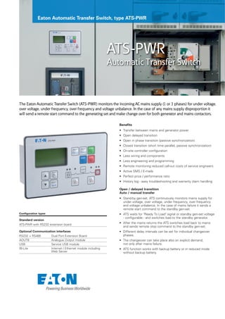

The Eaton Automatic Transfer Switch (ATS-PWR) monitors mains power for abnormalities and automatically starts a generator to provide backup power if issues are detected. It then switches the load to the generator. When mains power is restored, it returns the load to mains and stops the generator. The ATS-PWR offers benefits like remote monitoring, history logging for troubleshooting, and configurable transfer settings. It can be used for standby generator applications to provide backup power in the event of a mains failure.