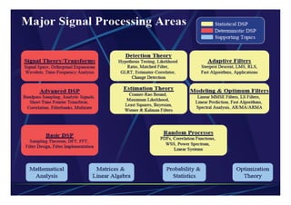
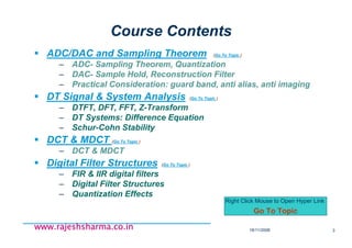
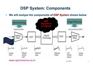
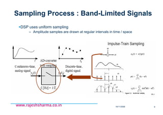
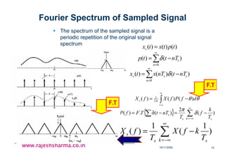
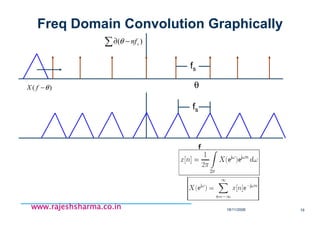
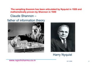
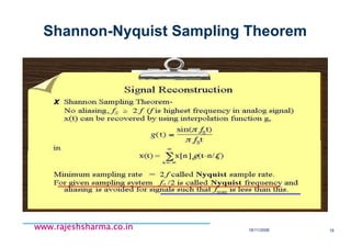
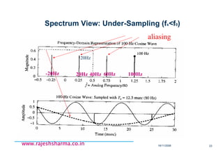
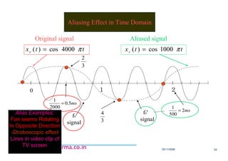
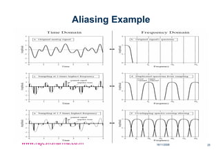
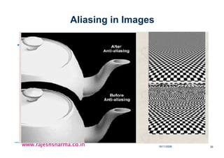
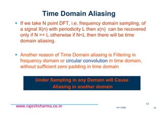
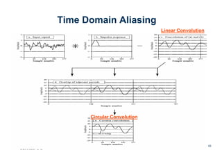
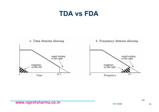
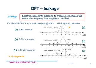
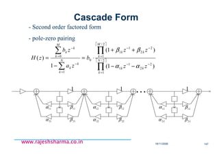
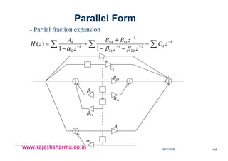
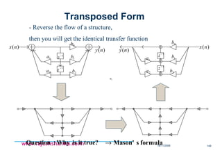
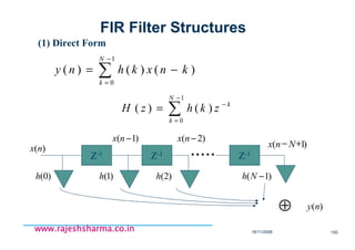
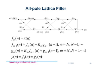
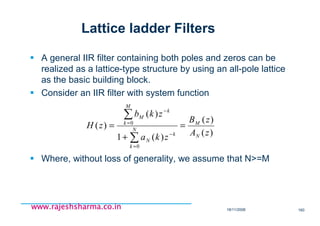
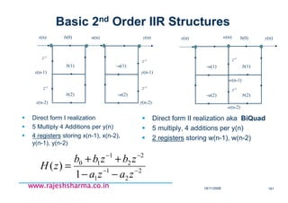
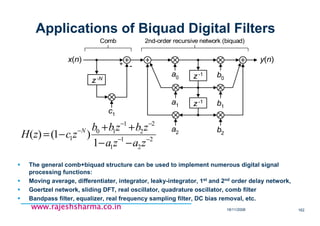
The document provides an overview of digital signal processing (DSP) fundamentals, including key concepts such as analog-to-digital conversion, sampling theorem, and digital filter structures. It discusses how DSP algorithms work on signals, the importance of sampling frequency for signal reconstruction, and the implications of aliasing in signal processing. Additionally, practical considerations and techniques for improving conversion accuracy, such as prefiltering and interpolation methods, are addressed.
![18/11/2008 7
www.rajeshsharma.co.inwww.rajeshsharma.co.inwww.rajeshsharma.co.inwww.rajeshsharma.co.in
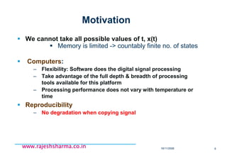
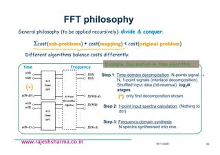
Objective….
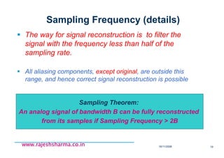
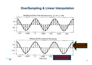
The sampling should not yield any loss of the information.
The problem is how to choose the sampling Frequency Fs.
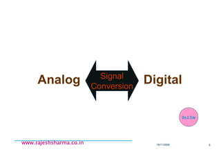
Analog
To
Digital
DSP
Digital
To
Analog
)(txa
][nx ][ny )(tya
A-to-D Conversion D-to-A Conversion
Sampling](https://image.slidesharecdn.com/dspfundamentalspart-ii-180730074432/85/Dsp-fundamentals-part-ii-7-320.jpg)
![18/11/2008 8
www.rajeshsharma.co.inwww.rajeshsharma.co.inwww.rajeshsharma.co.inwww.rajeshsharma.co.in
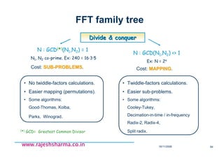
Analog to Digital Conversion
ADC
x(t) x[n]
A-to-D conversion constitute of](https://image.slidesharecdn.com/dspfundamentalspart-ii-180730074432/85/Dsp-fundamentals-part-ii-8-320.jpg)
![18/11/2008 13
www.rajeshsharma.co.inwww.rajeshsharma.co.inwww.rajeshsharma.co.inwww.rajeshsharma.co.in
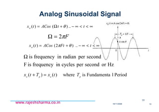
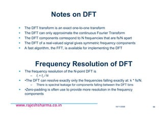
Discrete Time Sinusoid
A Discrete Time Sinusoid is periodic only if its frequency f is rational
number
2
1
2
1samplepercycleinfrequencyis
sampleperradianinfrequencyis
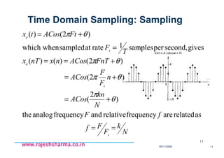
)2(][
2&NumberSample:riableinteger vais
..)()(
<<−
<<−
∞<<∞−+=
=
∞<<∞−+=
ff
nfnACosnx
fn
nnACosnx
πωπω
θπ
πω
θω
13
N
k
fnnxNnx ==+ ifonly:allfor)()(i.e](https://image.slidesharecdn.com/dspfundamentalspart-ii-180730074432/85/Dsp-fundamentals-part-ii-13-320.jpg)
![18/11/2008 27
www.rajeshsharma.co.inwww.rajeshsharma.co.inwww.rajeshsharma.co.inwww.rajeshsharma.co.in
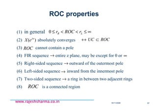
Digital-to-Analog Conversion
DAC
y(n) y(t)
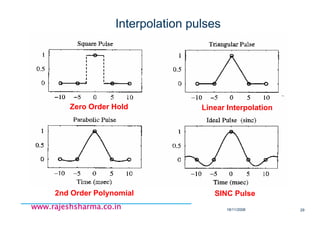
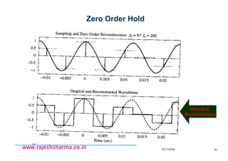
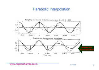
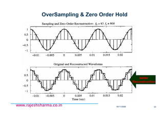
D-to-A conversion is implemented based on the
principle of interpolation:
∑
∞
−∞=
−=
n
snTtpnyty )(][)(
p(t) is the characteristic pulse shape of the converter.](https://image.slidesharecdn.com/dspfundamentalspart-ii-180730074432/85/Dsp-fundamentals-part-ii-27-320.jpg)
![18/11/2008 28
www.rajeshsharma.co.inwww.rajeshsharma.co.inwww.rajeshsharma.co.inwww.rajeshsharma.co.in
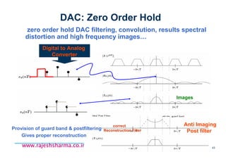
DAC: Digital-to-Analog Conversion
• The operation is equivalent to pass the discrete
sequence through a system, convolution, with
the impulse response of DAC i.e. p(t)
∑
∞
−∞=
−=
n
snTtpnyty )(][)(
Reconstructed
Signal
Discrete Time Signal &
Interpolation Pulse](https://image.slidesharecdn.com/dspfundamentalspart-ii-180730074432/85/Dsp-fundamentals-part-ii-28-320.jpg)

![18/11/2008 35
www.rajeshsharma.co.inwww.rajeshsharma.co.inwww.rajeshsharma.co.inwww.rajeshsharma.co.in
Shannon’s Solution
tf
tf
tg
s
s
π
π )sin(
)( =
)(][
0|)(~)(|),(][)()()(~
s
ss
nTxnxwhere
ttxtxnTtgnxdtgnTxtx
=
∀=−−=−= ∑∫∑ ττ
{ }
sT
ffXtxFT
2
1
0)()( ≥∀==
•Provided
•-fs/2 •fs/2 •
•f
•G(f)
•FT](https://image.slidesharecdn.com/dspfundamentalspart-ii-180730074432/85/Dsp-fundamentals-part-ii-35-320.jpg)
![18/11/2008 39
www.rajeshsharma.co.inwww.rajeshsharma.co.inwww.rajeshsharma.co.inwww.rajeshsharma.co.in
A/D Conversion
Sample&
Hold
A/D
Conversion
aliasinganti −
)(txc
)(tha
)(txa )(txo
1 2
)(txa
)(ts
)(txs
)(tho
)(txo
hold
order-zero
C/D Quantizer Coder
)(txo
][ˆ nxB
][ˆ nxB
][nx ][ˆ nx
<<
=
otherwise
Tt
th
,0
0,1
)(0
↑
0
t
1
T
∑∑
∞
−∞=
∞
−∞=
−⋅=−⋅=
nn
as nTtnxnTttxtx )()()()()( δδ1
2
3
3
∑ −⋅=∗=
n
oso nTthnxtxthtx )()()()()( 0
)(nTxa↑
t
)(txa )(txo
0 T 2T 3T
)]([)(ˆ nxQnx =
BB
XX
22
2 max
1
max
==∆ +
bits,1+B
B
BB aaaaaaaa −−−
⋅++⋅+⋅+⋅−= 2222 2
2
1
1
0
0210 LL
)complements2'(
∆2
∆
2
∆
2
3∆ )(nx
4](https://image.slidesharecdn.com/dspfundamentalspart-ii-180730074432/85/Dsp-fundamentals-part-ii-39-320.jpg)
![18/11/2008 40
www.rajeshsharma.co.inwww.rajeshsharma.co.inwww.rajeshsharma.co.inwww.rajeshsharma.co.in
Signal-to-Quantizing Noise Ratio
)(log208.1002.6)*12*2log(.10log10 max
102
max
2
2
2
2
dB
X
B
X
SNR
x
xB
e
x
σ
σ
σ
σ
⋅−+==⋅=
=
∆
=
∆
=
∆
≤<
∆
−−=
∫
∆
∆−
−2/
2/
max
222
22
12
2
12
1
2
)(
2
),()(ˆ)(
X
dee
nenxnxne
B
eσ
4
dBB
X
25.16SNRthen,
)inclusion99.93%gives4(.4/take
signalddistribute-Gaussianofcasein the
maxx
−≈
= σσ
(PCM)codingarithmiclog-
codinglinear-
operationrenttranspa],[ˆ][ˆCoding nxnx B⇔
Noise Power](https://image.slidesharecdn.com/dspfundamentalspart-ii-180730074432/85/Dsp-fundamentals-part-ii-40-320.jpg)
![18/11/2008 41
www.rajeshsharma.co.inwww.rajeshsharma.co.inwww.rajeshsharma.co.inwww.rajeshsharma.co.in
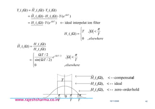
D/A Conversion
Scaled
by Xm
convert to
Impulse
Zero-order
hold
D/A
Conversoin
Compensated
Reconstruction
Filter
][ny
][ny
)(tyo
)(tyo
)(tyr
)( ΩjHo
)(
~
ΩjH r
2/
0
2
sin2
)(
,0
0,1
)(
)()()(
Tj
o
n
oo
e
t
jH
otherwise
Tt
th
nTthnyty
Ω−
⋅
Ω
Ω
=Ω
<<
=
−⋅= ∑
∑
∑
∑ ∫
∫∑
+Ω=←Ω⋅=
⋅Ω⋅=
⋅−⋅=
−=Ω
ΩΩ
Ω−
Ω−
∞
∞−
−Ω−
∞
∞−
Ω−
k
a
TjTj
n
nTj
o
n
nTjnTtj
o
n
tj
oo
T
k
jjY
T
eYjHeY
ejHny
edtenTthny
dtenTthnyjY
)
2
(
1
)()()(
)(][
)(][
)(][)(
0
)(
π](https://image.slidesharecdn.com/dspfundamentalspart-ii-180730074432/85/Dsp-fundamentals-part-ii-41-320.jpg)
![18/11/2008 44
www.rajeshsharma.co.inwww.rajeshsharma.co.inwww.rajeshsharma.co.inwww.rajeshsharma.co.in
Multirate Processing for A/D and D/A Conversions
Low-order
Anti-aliasing
Filter
A/D
conversion
Sharp
Lowpass
Filter
a aaab d1c 2c
M↓
][nx][ˆ nx)(txa
)(txc
doversample digital
(1)Oversampling-Decimation based A/D Conversion
(2) Interpolation - Low-order Reconstruction based D/A conversion
L↑
)(tyr][ny ][ˆ ny D/A
Conversion
Simple
Reconstruction
Filter
a aaab c d
)(tyDA
filter
imaginganti −](https://image.slidesharecdn.com/dspfundamentalspart-ii-180730074432/85/Dsp-fundamentals-part-ii-44-320.jpg)
![18/11/2008 45
www.rajeshsharma.co.inwww.rajeshsharma.co.inwww.rajeshsharma.co.inwww.rajeshsharma.co.in
Over Sampling-Decimation based A/D Conversion
Low-order
Anti-aliasing
Filter
A/D
conversion
Sharp
Lowpass
Filter
a aaab d1c 2c
M↓
][nx][ˆ nx)(txa
)(txc
a
b
d
CN Ω=ΩΩ=Ω
−
stoppass ,
LPFanalogorderLow
signalanalogFilteredLP
1c
2c
sampling)(over
(A/D)Sampling
NCs Ω+Ω=Ω
M
π
ω =N
LPFdigitalorder-High
signal1):(MdecimatedandFiltered
doversample digital](https://image.slidesharecdn.com/dspfundamentalspart-ii-180730074432/85/Dsp-fundamentals-part-ii-45-320.jpg)
![18/11/2008 46
www.rajeshsharma.co.inwww.rajeshsharma.co.inwww.rajeshsharma.co.inwww.rajeshsharma.co.in
Interpolation - Low-order Reconstruction based D/AC
1b
2b
L↑
)(tyr][ny ][ˆ ny
a
d
CN
T
Ω−=ΩΩ=Ω
−
''
2
,
LPFanalogorderLow
stopp
π
SignalOutputtedReconstruc
=
filterioninterpolat
dcompensate
LPFdigitalorder-High
N
L
π
ω
signalL):(1edInterpolat
D/A
Conversion
Simple
Reconstruction
Filter
a aaab c d
)(tyDA
filter
imaginganti −
c
convertedD/AbetoSignal](https://image.slidesharecdn.com/dspfundamentalspart-ii-180730074432/85/Dsp-fundamentals-part-ii-46-320.jpg)
![18/11/2008 48
www.rajeshsharma.co.inwww.rajeshsharma.co.inwww.rajeshsharma.co.inwww.rajeshsharma.co.in
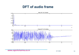
Fourier analysis - tools
Input Time Signal Frequency spectrum
∑
−
=
−
⋅=
1N
0n
N
nkπ2
j
es[n]
N
1
kc~
Discrete
DiscreteDFSDFSPeriodic
(period T)
ContinuousDTFT
Aperiodic
DiscreteDFTDFT
nfπ2je
n
s[n]S(f) −⋅
∞+
−∞=
= ∑
0
0.5
1
1.5
2
2.5
0 2 4 6 8 10 12
time, tk
0
0.5
1
1.5
2
2.5
0 1 2 3 4 5 6 7 8
time, tk
∑
−
=
−
⋅=
1N
0n
N
nkπ2
j
es[n]
N
1
kc~
dt
tfπj2
es(t)S(f)
−∞+
∞−
⋅= ∫
dt
T
0
tωkjes(t)
T
1
kc ∫
−⋅⋅=Periodic
(period T)
Discrete
ContinuousFTFTAperiodic
FSFS
Continuous
0
0.5
1
1.5
2
2.5
0 1 2 3 4 5 6 7 8
time, t
0
0.5
1
1.5
2
2.5
0 2 4 6 8 10 12
time, t
Note: j =√√√√-1, ωωωω = 2ππππ/T, s[n]=s(tn), N = No. of samples](https://image.slidesharecdn.com/dspfundamentalspart-ii-180730074432/85/Dsp-fundamentals-part-ii-48-320.jpg)
![18/11/2008 49
www.rajeshsharma.co.inwww.rajeshsharma.co.inwww.rajeshsharma.co.inwww.rajeshsharma.co.in
Frequency Domain Sampling: DFS
A Discrete Time Periodic Signal of fundamental period N may
consist of frequency components separated by
The Fourier Series representation of the discrete time periodic
signal will contain at the most N frequency components…
Discrete Time Fourier Series (DTFS): DFS
49
N
f
N
1or2 == πω
1,......1,0for][
1
0
/2
−== ∑
−
=
−
NkenxC
N
n
Nknj
k
π](https://image.slidesharecdn.com/dspfundamentalspart-ii-180730074432/85/Dsp-fundamentals-part-ii-49-320.jpg)
![18/11/2008 50
www.rajeshsharma.co.inwww.rajeshsharma.co.inwww.rajeshsharma.co.inwww.rajeshsharma.co.in
Discrete Fourier Series (DFS)
N consecutive samples of s[n]N consecutive samples of s[n]
completely describe s in time orcompletely describe s in time or
frequency domains.frequency domains.
DFS generate periodic ck
with same signal period
∑
−
=
⋅=
1N
0k
N
nk2π
j
ekcs[n] ~
Synthesis: finite sum ⇐ band-limited s[n]
Band-limited signal s[n], period = N.
mk,δ
1N
0n
N
-m)n(k2π
j
e
N
1
=
−
=
∑
Kronecker’s delta
Orthogonality in DFS:
synthesis
synthesis
∑
−
=
−
⋅=
1N
0n
N
nk2π
j
es[n]
N
1
kc~
Note:Note: ck+N = ck ⇔⇔⇔⇔ same period N
i.e. time periodicity propagates to frequencies!i.e. time periodicity propagates to frequencies!
DFS defined as:DFS defined as:
~~~~
analysis
analysis](https://image.slidesharecdn.com/dspfundamentalspart-ii-180730074432/85/Dsp-fundamentals-part-ii-50-320.jpg)
![18/11/2008 51
www.rajeshsharma.co.inwww.rajeshsharma.co.inwww.rajeshsharma.co.inwww.rajeshsharma.co.in
DFS analysis
DFS of periodic discreteDFS of periodic discrete
11--Volt squareVolt square--wavewave
⋅
−
−
±+=
=
otherwise,
N
kπ
sin
N
kLπ
sin
N
N
1)(Lkπ
j
e
2N,...N,0,k,
N
L
kc~
0.6
0 1 2 3 4 5 6 7 8 9 10 k
1
0 2 4 5 6 7 8 9 10 n
θk
-0.4π
0.2
0.24 0.24
0.6 0.6
0.24
1
0.24
-0.2π
0.4π
0.2π
-0.4π
-0.2π
0.4π
0.2π
0.6 ck
~
am
plitude
am
plitude
phase
phase
Discrete signalsDiscrete signals ⇒⇒⇒⇒⇒⇒⇒⇒ periodic frequency spectra.periodic frequency spectra.
Compare to continuous rectangular function
-5 0 1 2 3 4 5 6 7 8 9 10 n
0 L N
s[n]
1
s[n]: period NN, duty factor L/NL/N](https://image.slidesharecdn.com/dspfundamentalspart-ii-180730074432/85/Dsp-fundamentals-part-ii-51-320.jpg)
![18/11/2008 52
www.rajeshsharma.co.inwww.rajeshsharma.co.inwww.rajeshsharma.co.inwww.rajeshsharma.co.in
DFS properties
Time FrequencyTime Frequency
Homogeneity a·s[n] a·S(k)
Additivity s[n] + u[n] S(k)+U(k)
Linearity a·s[n] + b·u[n] a·S(k)+b·U(k)
Multiplication * s[n] ·u[n]
Convolution * S(k)·U(k)
Time shifting s[n - m]
Frequency shifting S(k - h)
∑
−
=
⋅
1N
0h
h)-S(h)U(k
N
1
∑
−
=
−⋅
1N
0m
m]u[ns[m]
S(k)e T
mk2π
j
⋅
⋅
−
s[n]T
th2π
j
e ⋅
+](https://image.slidesharecdn.com/dspfundamentalspart-ii-180730074432/85/Dsp-fundamentals-part-ii-52-320.jpg)
![18/11/2008 53
www.rajeshsharma.co.inwww.rajeshsharma.co.inwww.rajeshsharma.co.inwww.rajeshsharma.co.in
Discrete Time FT (DTFT)
Holds for aperiodic signals
∑
−
=
−
⋅=
1N
0n
N
nkπ2
j
es[n]
N
1
kc~
n
s[n] 1 period
n
s[n]
∫⋅=
2π
0
nfπ2j
dfS(f)e
2π
1
s[n]
synthesis
synthesis
nfπ2j
n
es[n]S(f) −
+∞
−∞=
⋅= ∑analysis
analysis
Obtained from DFS as N → ∞
DTFT defined as:DTFT defined as:](https://image.slidesharecdn.com/dspfundamentalspart-ii-180730074432/85/Dsp-fundamentals-part-ii-53-320.jpg)
![18/11/2008 54
www.rajeshsharma.co.inwww.rajeshsharma.co.inwww.rajeshsharma.co.inwww.rajeshsharma.co.in
DTFT - Convolution
Digital Linear Time Invariant systemDigital Linear Time Invariant system: obeys superposition principle.
∑
∞
=
⋅−=∗=
0m
h[m]m]x[nh[n]x[n]y[n]x[n] h[n]
ConvolutionConvolution
X(f) H(f) Y(f) = X(f) · H(f)
DIGITAL LTI
SYSTEM
h[n]
x[n] y[n]
h[t] = impulse response
DIGITAL
LTI
SYSTEM
0 n
δ[n]
1
0 n
h[n]
0 f
DTFT(δ[n])
1](https://image.slidesharecdn.com/dspfundamentalspart-ii-180730074432/85/Dsp-fundamentals-part-ii-54-320.jpg)
![18/11/2008 55
www.rajeshsharma.co.inwww.rajeshsharma.co.inwww.rajeshsharma.co.inwww.rajeshsharma.co.in
DTFT - Sampling/convolution
s[n] * u[n] ⇔⇔⇔⇔ S(f) · U(f) ,
s[n] · u[n] ⇔⇔⇔⇔ S(f) * U(f)
(From FT properties)
Time Frequency
t f
s(t) S(f)
t f
ts fsu(t) U(f)
n f
s”[n] S”(f)
Sampling s(t)
Multiply s(t) by
Shah = Щ(t)](https://image.slidesharecdn.com/dspfundamentalspart-ii-180730074432/85/Dsp-fundamentals-part-ii-55-320.jpg)
![18/11/2008 56
www.rajeshsharma.co.inwww.rajeshsharma.co.inwww.rajeshsharma.co.inwww.rajeshsharma.co.in
Discrete FT (DFT)
∑
−
=
⋅=
1N
0k
N
nk2π
j
ekcs[n] ~synthesis
synthesis
DFT defined as:DFT defined as:
Note:Note: ck+N = ck ⇔⇔⇔⇔ spectrum has period N
~~~~
∑
−
=
−
⋅=
1N
0n
N
nk2π
j
es[n]
N
1
kc~analysis
analysis
Applies to discrete time and frequency signals.
Same form of DFS but for aperiodic signals:
signal treated as periodic for computational purpose only.
DFT bins located @ analysis frequencies fm
DFT ~ bandpass filters centred @ fm
Frequency resolution
Analysis frequencies fAnalysis frequencies fmm
1N...20,m,
N
fm
f S
m −=
⋅
=](https://image.slidesharecdn.com/dspfundamentalspart-ii-180730074432/85/Dsp-fundamentals-part-ii-56-320.jpg)
![18/11/2008 57
www.rajeshsharma.co.inwww.rajeshsharma.co.inwww.rajeshsharma.co.inwww.rajeshsharma.co.in
Basis Vectors of DFT
•DFT & IDFT
•Can be written as
xFiX
xFX
NxxxxX
ni
n
N
rr
rr
•=
•=
−++++= −−−−
..1,
..1,2
)1(21
)(
)1(
)1(...)2()1()0(.1)1( ξξξ
•DFT projects x[n] on the basis vectors formed by the rows of F](https://image.slidesharecdn.com/dspfundamentalspart-ii-180730074432/85/Dsp-fundamentals-part-ii-57-320.jpg)
![18/11/2008 58
www.rajeshsharma.co.inwww.rajeshsharma.co.inwww.rajeshsharma.co.inwww.rajeshsharma.co.in
DFT - pulse & sinewave
ck = (1/N) e-jπk(N-1)/N sin(πk)/ sin(πk/N)~~
a) rectangular pulse, width Na) rectangular pulse, width N
r[n] =
1 , if 0≤n≤N-1
0 , otherwise
b) real sinewave, frequency fb) real sinewave, frequency f00 = L/N= L/N
cs[n] = cos(j2πf0n)
ck = (1/N) ejπ{(Nf0-k)-(Nf0 -k)/N} (½) sin{π(Nf0-k)}/ sin{π(Nf0-k)/N)} +
(1/N) ejπ{(Nf0+k)-(Nf0+k)/N} (½) sin{π(Nf0+k)}/ sin{π(Nf0+k)/N)}
~~
i.e. L complete cycles in N sampled points
-5 0 1 2 3 4 5 6 7 8 9 10 n
0 N
s[n]
1
0 1 2 3 4 5 6 7 8 9 10 k
1 1
ck
~](https://image.slidesharecdn.com/dspfundamentalspart-ii-180730074432/85/Dsp-fundamentals-part-ii-58-320.jpg)
![18/11/2008 60
www.rajeshsharma.co.inwww.rajeshsharma.co.inwww.rajeshsharma.co.inwww.rajeshsharma.co.in
Linearity a·s[n] + b·u[n] a·S(k)+b·U(k)
Multiplication s[n] ·u[n]
Convolution S(k)·U(k)
Time shifting s[n - m]
Frequency shifting S(k - h)
∑
−
=
⋅
1N
0h
h)-S(h)U(k
N
1
∑
−
=
−⋅
1N
0m
m]u[ns[m]
S(k)e T
mk2π
j
⋅
⋅
−
s[n]T
th2π
j
e ⋅
+
DFT properties
Time FrequencyTime Frequency](https://image.slidesharecdn.com/dspfundamentalspart-ii-180730074432/85/Dsp-fundamentals-part-ii-60-320.jpg)
![18/11/2008 61
www.rajeshsharma.co.inwww.rajeshsharma.co.inwww.rajeshsharma.co.inwww.rajeshsharma.co.in
DTFT vs. DFT vs. DFS
t
0 T /2 T 2T f
s[n] S(f)
f
~
cK
t
s”[n] D FTIDFT
(a)
(a) Aperiodic discrete signal.
(b)
(b) DTFT transform magnitude.
(c)
(c) Periodic version of (a).
(d)
(d) DFS coefficients = samples of (b).
(e)
(e) Inverse DFT estimates a single period of s[n]
(f)
(f) DFT estimates a single period of (d).](https://image.slidesharecdn.com/dspfundamentalspart-ii-180730074432/85/Dsp-fundamentals-part-ii-61-320.jpg)
![18/11/2008 66
www.rajeshsharma.co.inwww.rajeshsharma.co.inwww.rajeshsharma.co.inwww.rajeshsharma.co.in
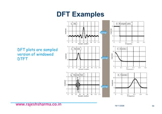
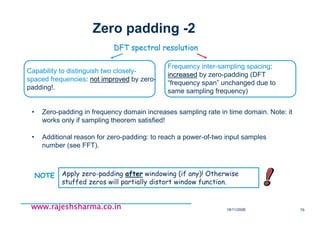
1. Cosine wave
DFT - leakage example
s(t) FT{s(t)}
2. Rectangular window4. Sampling function1. Cosine wave
0.25 Hz Cosine wave
3. Windowed cos wave5. Sampled windowed
wave
Leakage caused by sampling for a nonLeakage caused by sampling for a non--integer number of periodsinteger number of periods
s[n] · u[n] ⇔⇔⇔⇔ S(f) * U(f)
(Convolution)](https://image.slidesharecdn.com/dspfundamentalspart-ii-180730074432/85/Dsp-fundamentals-part-ii-66-320.jpg)
![18/11/2008 67
www.rajeshsharma.co.inwww.rajeshsharma.co.inwww.rajeshsharma.co.inwww.rajeshsharma.co.in
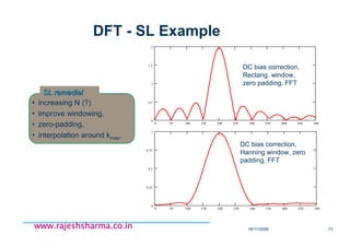
2. Rectangular window4. Sampling function1. Cosine wave
1. Cosine wave3. Windowed cos wave5. Sampled windowed
wave
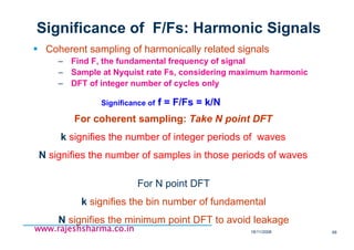
DFT - coherent sampling
s(t) FT{s(t)}
Coherent sampling: NC input cycles exactly into NS = NC (fS/fIN) sampled points.
s[n] ·u[n] ⇔⇔⇔⇔ S(f) * U(f)
(Convolution)
0.2 Hz Cosine wave](https://image.slidesharecdn.com/dspfundamentalspart-ii-180730074432/85/Dsp-fundamentals-part-ii-67-320.jpg)
![18/11/2008 72
www.rajeshsharma.co.inwww.rajeshsharma.co.inwww.rajeshsharma.co.inwww.rajeshsharma.co.in
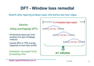
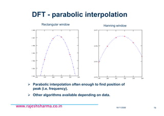
DFT - Window choice
Window type -3 dB Main-
lobe width
[bins]
-6 dB Main-
lobe width
[bins]
Max sidelobe
level
[dB]
Sidelobe roll-off
[dB/decade]
Rectangular 0.89 1.21 -13.2 20
Hamming 1.3 1.81 - 41.9 20
Hanning 1.44 2 - 31.6 60
Blackman 1.68 2.35 -58 60
Common windows characteristics
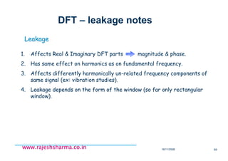
NB: Strong DC component can shadow nearby small signals. RemoveNB: Strong DC component can shadow nearby small signals. Remove it!it!
Far & strong interfering components ⇒⇒⇒⇒⇒⇒⇒⇒ high roll-off rate.
Near & strong interfering components ⇒⇒⇒⇒⇒⇒⇒⇒ small max sidelobe level.
Accuracy measure of single tone ⇒⇒⇒⇒⇒⇒⇒⇒ wide main-lobe
Observed signalObserved signal Window wish listWindow wish list](https://image.slidesharecdn.com/dspfundamentalspart-ii-180730074432/85/Dsp-fundamentals-part-ii-72-320.jpg)
![18/11/2008 76
www.rajeshsharma.co.inwww.rajeshsharma.co.inwww.rajeshsharma.co.inwww.rajeshsharma.co.in
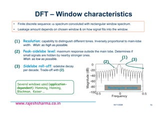
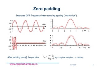
DFT - scalloping loss (SL)
Worst case when f0 falls
exactly midway between 2
successive bins (|r|=½)
SL
bin, k
Note:Note: Non-rectangular windows broaden
DFT main lobe ⇒⇒⇒⇒ SL less severeSL less severe
Correction depends on window used.Correction depends on window used.
f0
Frequency error: εf = r fS/N,
relative error: εR=εf / f0 = r/[(kmax+r)] εR
≤≤≤≤ 1/(1+2 kmax)
kmax
kmax
bin, k
We’re lucky here!
May impact on data
interpretation (wrong f0!)
Input frequency f0 btwn. bin
centres causes magnitude loss
SL = 20 Log10(|cr+kmax /ckmax|)
~~~~
|r| ≤ ½f0 = (kmax + r) fS/N](https://image.slidesharecdn.com/dspfundamentalspart-ii-180730074432/85/Dsp-fundamentals-part-ii-76-320.jpg)
![18/11/2008 80
www.rajeshsharma.co.inwww.rajeshsharma.co.inwww.rajeshsharma.co.inwww.rajeshsharma.co.in
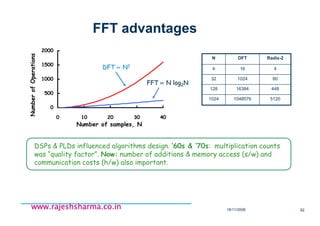
Efficient DFT calculation: FFT
∑∑
−
=
−
=
−
⋅=⋅=
1N
0n
kn
N
1N
0n
N
nk2π
j
k Ws[n]
N
1
es[n]
N
1
c~
WN
n,k = twiddle factors
k = 0,1 .. N-1
DFT
Direct DFT calculation redundancy
WN
kn periodic function calculated many times.
W8
0,k
W8
4,k
W8
2,k
W8
5,k
W8
6,k
W8
3,k
W8
7,k
W8
1,k
Algorithms (= Fast Fourier Transform) developed to compute N-points DFT with ~
Nlog2N multiplications (complexity O(Nlog2N) ).
Direct DFT calculation requires ~N2
complex multiplications.
complexity O(N2)
VERY
BAD
VERY
BAD
!!](https://image.slidesharecdn.com/dspfundamentalspart-ii-180730074432/85/Dsp-fundamentals-part-ii-80-320.jpg)
![18/11/2008 85
www.rajeshsharma.co.inwww.rajeshsharma.co.inwww.rajeshsharma.co.inwww.rajeshsharma.co.in
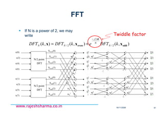
(Some) FFT concepts
Butterfly: basic FFT calculation element.
s[k+N/2]
s[k]
WN
N/2
WN
0
1. Decimation-in-time ⇒⇒⇒⇒⇒⇒⇒⇒ time data shuffling.
2. Decimation-in-frequency ⇒⇒⇒⇒⇒⇒⇒⇒ frequency data shuffling.
3. In-place computation: no auxiliary storage needed, allowed by most algorithms.
4. DFT pruning: only few bins needed or different from zero ⇒⇒⇒⇒⇒⇒⇒⇒ only they get calculated
(ex: Goertzel algorithm).
5. Real-data case: Mirroring effect in DFT coeffs. ⇒⇒⇒⇒⇒⇒⇒⇒ only half of them calculated.
6. N power-of-two: Many common FFT algorithms work with power-of-two number of
inputs. When they are not ⇒⇒⇒⇒⇒⇒⇒⇒ pad inputs with zeroes.
Dual approach: data to be reordered in
time or in frequency!](https://image.slidesharecdn.com/dspfundamentalspart-ii-180730074432/85/Dsp-fundamentals-part-ii-85-320.jpg)
![18/11/2008 86
www.rajeshsharma.co.inwww.rajeshsharma.co.inwww.rajeshsharma.co.inwww.rajeshsharma.co.in
Systems spectral analysis (hints)
System analysis: measure inputSystem analysis: measure input--output relationshipoutput relationship..
DIGITAL LTI
SYSTEM
h[n]
x[n] y[n]
H(f) : LTI transfer functionH(f) : LTI transfer function
∑
∞
=
⋅−=∗=
0m
h[m]m]x[nh[n]x[n]y[n]x[n] h[n]
X(f) H(f) Y(f) = X(f) · H(f)
DIGITAL
LTI
SYSTEM
0 n
δδδδ[n]
1
0 n
h[n]
h[t] = impulse response
Linear Time InvariantLinear Time Invariant
y[n] predicted from { x[n], h[t] }
Transfer function can be estimated by Y(f) / X(f)](https://image.slidesharecdn.com/dspfundamentalspart-ii-180730074432/85/Dsp-fundamentals-part-ii-86-320.jpg)
![18/11/2008 87
www.rajeshsharma.co.inwww.rajeshsharma.co.inwww.rajeshsharma.co.inwww.rajeshsharma.co.in
Estimating H(f) (hints)
(f)XX(f)(f)G *
xx ⋅= Power Spectral Density of x[t] (FT
of autocorrelation).
(f)XY(f)(f)G *
yx ⋅= Cross Power Spectrum of x[t] & y[t] (FT
of cross-correlation).
It is a check on
H(f) validity!
(f)G(f)G
(f)G
(f)C
yyxx
2
yx
xy
⋅
=
Coherence function
- values in [0,1]
- assess degree of linear relationship
between x[t] & y[t].
xx
yx
*
*
G
G
(f)XX(f)
(f)XY(f)
X(f)
Y(f)
H(f) =
⋅
⋅
== Transfer Function
(ex: beam !)](https://image.slidesharecdn.com/dspfundamentalspart-ii-180730074432/85/Dsp-fundamentals-part-ii-87-320.jpg)
![18/11/2008 89
www.rajeshsharma.co.inwww.rajeshsharma.co.inwww.rajeshsharma.co.inwww.rajeshsharma.co.in
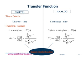
The Z Transform
Powerful tool for analyzing & designing DT systems
Generalization of the DTFT:
∑ −
n
fnj
enxDTFT π2
][:
fj
rez π2−
=
∑∑ −−−
=
n
n
n
fnjn
znxernxnxZ ][][:]}[{ 2π
∫
−
dtetxCTFT ftj π2
)(:
fjs πσ 2+=
∫∫
−+−
= dtetxdtetxtxL sttfj
)()(:)}({ )2( πσ](https://image.slidesharecdn.com/dspfundamentalspart-ii-180730074432/85/Dsp-fundamentals-part-ii-89-320.jpg)
![18/11/2008 90
www.rajeshsharma.co.inwww.rajeshsharma.co.inwww.rajeshsharma.co.inwww.rajeshsharma.co.in
- Fourier transform nj
n
j
enxeX ωω −
∞
−∞=
∑= ][)(
limited as it can handle stable systems only.
)( ωj
eX converges, or exists if ∑ ∞<|][| nx
i.e., stable system → Fourier Transform converges
Fourier Transform Limitation
Require to analyze digital system in general](https://image.slidesharecdn.com/dspfundamentalspart-ii-180730074432/85/Dsp-fundamentals-part-ii-90-320.jpg)
![18/11/2008 91
www.rajeshsharma.co.inwww.rajeshsharma.co.inwww.rajeshsharma.co.inwww.rajeshsharma.co.in
nj
n
nj
r ernxeXLet ωω −
∞
−∞=
−
∑= )][()( converges if ∑ ∞<−
|][| n
rnx
Example:
||
2
1
1
2|2||)(|
|2||)(|
][2][
r
rereX
eeX
nunx
nnnjnnj
r
njnj
n
−
=<=
∞→=
=
∑∑
∑
−−−
−
ωω
ωω
→ converges if 2|| >r
The condition for convergence is relaxed!
FT generalization](https://image.slidesharecdn.com/dspfundamentalspart-ii-180730074432/85/Dsp-fundamentals-part-ii-91-320.jpg)
![18/11/2008 92
www.rajeshsharma.co.inwww.rajeshsharma.co.inwww.rajeshsharma.co.inwww.rajeshsharma.co.in
∑
∞
−∞=
−
=
==
n
n
zre
j
r znxeXzX jw ][|)()( ω
Representing the condition for convergence of
in terms of region of convergence i.e. ROC.
)( ωj
r eX
in case x[n] = 2n
u[n]
)( ωj
r eX exists for |r|>2.
ROC is |z| = |rejω|>2.
Z Transform](https://image.slidesharecdn.com/dspfundamentalspart-ii-180730074432/85/Dsp-fundamentals-part-ii-92-320.jpg)
![18/11/2008 93
www.rajeshsharma.co.inwww.rajeshsharma.co.inwww.rajeshsharma.co.inwww.rajeshsharma.co.in
In general, if ][][ nuanx n
=
az >ROC is
- In terms of ,)(zX
)( jw
eX is a special case
Where , or1=z 1=r
2
causal
Z Transform
UC: Unit Circle](https://image.slidesharecdn.com/dspfundamentalspart-ii-180730074432/85/Dsp-fundamentals-part-ii-93-320.jpg)
![18/11/2008 94
www.rajeshsharma.co.inwww.rajeshsharma.co.inwww.rajeshsharma.co.inwww.rajeshsharma.co.in
]1[][ −−−= nuanx n
1
1
1
1
0
1
1
1
1
1
11
1
1
)(1
]1[)(
−
−
−
−
∞
=
−
∞
=
−
−
−∞=
−
∞
−∞=
−
−
=
−
−
=
−
−=
−=−=
−=−−−=
∑∑
∑∑
az
za
za
za
zaza
zaznuazX
n
n
n
nn
n
nn
n
nn
ROC 11
<−
za az <: , or
2=|a|
Example](https://image.slidesharecdn.com/dspfundamentalspart-ii-180730074432/85/Dsp-fundamentals-part-ii-94-320.jpg)
![18/11/2008 95
www.rajeshsharma.co.inwww.rajeshsharma.co.inwww.rajeshsharma.co.inwww.rajeshsharma.co.in
11
1
0
2
1
1
1
3
1
1
1
)
2
1
()
3
1
()(
−−
−
−∞=
−
∞
=
−
−
−
+
=
−−= ∑∑
zz
zzzX
n
nn
n
nn
]1[)
2
1
(][)
3
1
(][ −−−−= nununx nn
3
1
>z
2
1
<z, 1/21/3
Two Sided Sequence](https://image.slidesharecdn.com/dspfundamentalspart-ii-180730074432/85/Dsp-fundamentals-part-ii-95-320.jpg)
![18/11/2008 96
www.rajeshsharma.co.inwww.rajeshsharma.co.inwww.rajeshsharma.co.inwww.rajeshsharma.co.in
(1)
(2)
(3)
(4)
(5)
(6)
(7)
][1][ zalln ↔δ
]1[
1
1
][ >
−
↔ z
z
nu
]1[
1
1
]1[ 1
<
−
↔−−− −
z
z
nu
][
1
1
][ 1
az
az
nua n
>
−
↔ −
]0,
,0,0[][
<∞
>↔− −
mifexceptzall
mifexceptzallzmn m
δ
][
1
1
]1[ 1
az
az
nua n
<
−
↔−−− −
][
)1(
][ 21
1
az
az
az
nuna n
>
−
↔ −
−
Z Transform Pairs](https://image.slidesharecdn.com/dspfundamentalspart-ii-180730074432/85/Dsp-fundamentals-part-ii-96-320.jpg)
![18/11/2008 98
www.rajeshsharma.co.inwww.rajeshsharma.co.inwww.rajeshsharma.co.inwww.rajeshsharma.co.in
a b c
(e.g.) If x[n] is a sum of 3 sequences whose poles
are a, b, c respectively,
There exist A possible as shown belowROC
All right-sided All left-sided
two left-sided two right-sided
a b c](https://image.slidesharecdn.com/dspfundamentalspart-ii-180730074432/85/Dsp-fundamentals-part-ii-98-320.jpg)
![18/11/2008 99
www.rajeshsharma.co.inwww.rajeshsharma.co.inwww.rajeshsharma.co.inwww.rajeshsharma.co.in
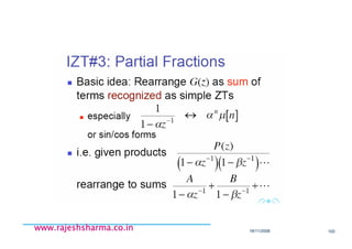
(1) Inspection method
(2) Power Series Expansion
(3) Partial Fraction Expansion →
omitted
(e.g.)
power series expansion
∑ ∑
∞
=
∞
−∞=
−
−+
=
−
=
1
1
][
)1(
)(
n n
n
nnn
znx
n
za
zX
=→ ][nx
00
1)1( 1
≤
≥− +
n
n
n
an
n
azazzX >+= −
)1log()( 1
{
Inverse Z Transform
Useful
→](https://image.slidesharecdn.com/dspfundamentalspart-ii-180730074432/85/Dsp-fundamentals-part-ii-99-320.jpg)
![18/11/2008 101
www.rajeshsharma.co.inwww.rajeshsharma.co.inwww.rajeshsharma.co.inwww.rajeshsharma.co.in
(1) Linearity
(2) Time shifting
)()(][][ 2121 zbXzaXnbxnax +↔+
)(][ zXznnx on
o
−
↔−
Z Transform Properties
(3) Multiplication by an Exponential Sequence
)(][
o
n
o
z
z
Xnxz ↔
(4) Differentiation of X(z)
XRROCzx
dx
d
znnx =−↔ ][][](https://image.slidesharecdn.com/dspfundamentalspart-ii-180730074432/85/Dsp-fundamentals-part-ii-101-320.jpg)
![18/11/2008 102
www.rajeshsharma.co.inwww.rajeshsharma.co.inwww.rajeshsharma.co.inwww.rajeshsharma.co.in
(5) Conjugation of Complex Sequence
(6) Time-Reversal
(7) Convolution-Integration
XRROCzXnx =↔ )(][ ***
)
1
(][
1
)
1
(][ *
**
z
Xnx
R
ROC
z
Xnx
X
↔−
=↔−
)()(][*][ 2121 zXzXnxnx ↔
(8) Initial Value Theorem
)(lim]0[ zXx
z ∞→
=](https://image.slidesharecdn.com/dspfundamentalspart-ii-180730074432/85/Dsp-fundamentals-part-ii-102-320.jpg)
![18/11/2008 103
www.rajeshsharma.co.inwww.rajeshsharma.co.inwww.rajeshsharma.co.inwww.rajeshsharma.co.in
(1)
① Causal
② Stable
① Outward
② UC ROC
][)
2
1
(][ nunx n
=
nn
n
zzX −
∞
=
∑= )
2
1
()(
0
1
2
1
1
1
−
−
=
z
⊂
2
1
>z
2
1
1
2
1
1
ROC :
Stability & Causality](https://image.slidesharecdn.com/dspfundamentalspart-ii-180730074432/85/Dsp-fundamentals-part-ii-103-320.jpg)
![18/11/2008 104
www.rajeshsharma.co.inwww.rajeshsharma.co.inwww.rajeshsharma.co.inwww.rajeshsharma.co.in
(2)
① Anti Causal
② Unstable
① Inward
② UC ROC
]1[)
2
1
(][ −−−= nunx n
1
1
2
1
1
1
)
2
1
()(
−
−
−
−∞=
−
=−= ∑
z
zzX nn
n
2
1
<z
⊄
2
1
2
1
ROC :](https://image.slidesharecdn.com/dspfundamentalspart-ii-180730074432/85/Dsp-fundamentals-part-ii-104-320.jpg)
![18/11/2008 105
www.rajeshsharma.co.inwww.rajeshsharma.co.inwww.rajeshsharma.co.inwww.rajeshsharma.co.in
(3)
① Causal
② Unstable
ROC :
① Outward
② UC ROC
][)2(][ nunx n
=
1
0 21
1
2)( −
−
∞
= −
== ∑ z
zzX n
n
n
2>z
⊄
1 2
1 2](https://image.slidesharecdn.com/dspfundamentalspart-ii-180730074432/85/Dsp-fundamentals-part-ii-105-320.jpg)
![18/11/2008 106
www.rajeshsharma.co.inwww.rajeshsharma.co.inwww.rajeshsharma.co.inwww.rajeshsharma.co.in
(4)
① Anti Causal
② Stable
① Inward
② UC ROC
What do you find?
]1[2][ −−−= nunx n
1
1
21
1
2)( −
−
−
−∞= −
=−= ∑ z
zzX n
n
n
2<z
⊂
1 2
ROC :](https://image.slidesharecdn.com/dspfundamentalspart-ii-180730074432/85/Dsp-fundamentals-part-ii-106-320.jpg)
![18/11/2008 109
www.rajeshsharma.co.inwww.rajeshsharma.co.inwww.rajeshsharma.co.inwww.rajeshsharma.co.in
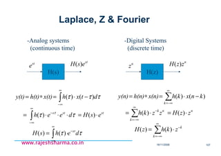
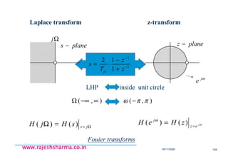
<Laplace-Transform> <z-Transform>
Stable : ROC includes Stable : ROC includes
j-axis UC
Causal : ROC Rightward Causal : ROC outward
),(),(
)()(
∞−∞ΩΩ →
=
Ω=
∞
∞−
−
∫
jH
dzezhsH
js
sz
),(),(
][)(
ππωωω
− →
=
=
∞
−∞=
−
∑
jez
n
n
eH
znhzH
j
Analog
LTI
x(t) y(t) Digital
LTI
x[n] y[n]
st
e
st
esH )( n
z n
zzH )(
z-planes-plane](https://image.slidesharecdn.com/dspfundamentalspart-ii-180730074432/85/Dsp-fundamentals-part-ii-109-320.jpg)
![18/11/2008 111
www.rajeshsharma.co.inwww.rajeshsharma.co.inwww.rajeshsharma.co.inwww.rajeshsharma.co.in
DT LTI Systems
CT LTI systems are described by ODEs
∑∑ ==
+=
M
k
k
k
k
N
k
k
k
k tx
dt
d
bty
dt
d
aty
01
)()()(
DT LTI systems are described by Difference Equations
s
ss
T
nTxTnx
dt
tdx )())1(()( −+
≈ • normalised wrt Ts ][]1[
)(
nxnx
dt
tdx
−+≈
Typical DT LTI system Difference Equations are
∑∑ ==
−+−=
M
k
k
N
k
k knxbknyany
01
][][][](https://image.slidesharecdn.com/dspfundamentalspart-ii-180730074432/85/Dsp-fundamentals-part-ii-111-320.jpg)
![18/11/2008 112
www.rajeshsharma.co.inwww.rajeshsharma.co.inwww.rajeshsharma.co.inwww.rajeshsharma.co.in
DT System Components
DIGITALDIGITAL ANALOGANALOG
(1) Expression
∑∑ ==
−+−=
M
k
k
N
k
k knxbknyany
01
],[][][ ∑∑ ==
+=
M
k
k
k
k
N
k
k
k
k tx
dt
d
bty
dt
d
aty
01
)()()(
(2) Circuit Elements
Adder
Multiplier
Delay
][][ 21 nxnx +
][nxa ⋅
a
]1[ −nx1−
z
R
L
C
VS
CS
iRv ⋅=
dt
di
Lv ⋅=
∫= idt
C
v
1
+
-](https://image.slidesharecdn.com/dspfundamentalspart-ii-180730074432/85/Dsp-fundamentals-part-ii-112-320.jpg)
![18/11/2008 114
www.rajeshsharma.co.inwww.rajeshsharma.co.inwww.rajeshsharma.co.inwww.rajeshsharma.co.in
DT System Response
Cz
za
zb
zX
zY
zH N
k
k
k
M
k
k
k
∈∀
−
==
∑
∑
=
−
=
−
1
0
1
)(
)(
)(
∑∑ ==
−+−=
N
i
i
N
i
i inhainbnh
10
][][][ δ
•z = r.ej2πf are the eigenvectors of the Difference Equation
•The Magnitude of the system response at each z is given by the
•System Transfer Function
•We resolve the i/p sequence x[n] on these eigenvectors z (ZT)
•Find the response at each Z (apply xfer func)
•Sum the responses back to get o/p (IZT)
z3
z1
z2
z4
a1
a2b1
b2
System i/p
System o/p?
b20
b1o
a2o
a1o](https://image.slidesharecdn.com/dspfundamentalspart-ii-180730074432/85/Dsp-fundamentals-part-ii-114-320.jpg)
![18/11/2008 115
www.rajeshsharma.co.inwww.rajeshsharma.co.inwww.rajeshsharma.co.inwww.rajeshsharma.co.in
Convolution Sum
So given a system and i/p, we do
][)(
)()()(
)(][
nyzY
zXzHzY
zXnx
⇒
=
⇒
System
•IZT
∑
∞
−∞=
−=
k
knxkhny ][][][
•Convolution
•Impulse
response](https://image.slidesharecdn.com/dspfundamentalspart-ii-180730074432/85/Dsp-fundamentals-part-ii-115-320.jpg)
![18/11/2008 116
www.rajeshsharma.co.inwww.rajeshsharma.co.inwww.rajeshsharma.co.inwww.rajeshsharma.co.in
Causality & Stability
an LTI system is causal if and
only if its impulse response is
zero for negative values of n
– i.e. system o/p does not depend
on future values of i/p
LTI system is Stable if its impulse
response is absolutely summable
∑
∞
=
−=
0
][][][
k
knxkhny
∞<∑
∞
−∞=
|][|
k
kh](https://image.slidesharecdn.com/dspfundamentalspart-ii-180730074432/85/Dsp-fundamentals-part-ii-116-320.jpg)

![18/11/2008 132
www.rajeshsharma.co.inwww.rajeshsharma.co.inwww.rajeshsharma.co.inwww.rajeshsharma.co.in
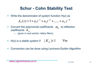
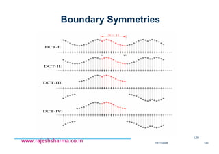
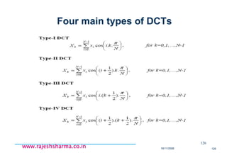
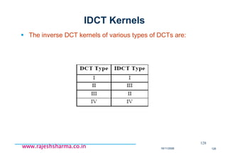
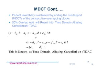
MDCT Cont…..
MDCT is based on DCT-IV and maps 2N real numbers
to N real numbers
It is designed for consecutive blocks of data where
second half of first block overlaps with first half of second
block.
otherwise it is not invertible during IMDCT process. ?????
132
∑
−
=
−=+++=
12
0
1,.....,1,0for)]
2
1
)(
22
1
([
N
n
nk
Nkk
N
n
N
CosxX
π
n
x
kX](https://image.slidesharecdn.com/dspfundamentalspart-ii-180730074432/85/Dsp-fundamentals-part-ii-132-320.jpg)
![18/11/2008 134
www.rajeshsharma.co.inwww.rajeshsharma.co.inwww.rajeshsharma.co.inwww.rajeshsharma.co.in
∑
−
=
−=+++=
1
0
12,.....,1,0for)]
2
1
)(
22
1
([
1 N
n
kn Nnk
N
n
N
CosX
N
y
π
2/),,,( RRRR cddcabba ++−−
2/),,,( RRRR effecddc ++−−
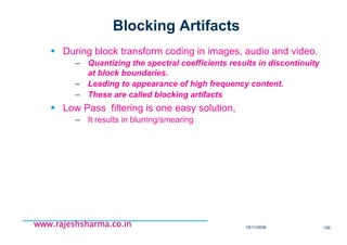
MDCT/IMDCT of a single block is not invertible
Because of Time Domain Aliasing after IMDCT,
– Due to 2N to N point mapping during MDCT…
Remember Undersampling ???
IMDCT {MDCT(a,b,c,d)} =
IMDCT {MDCT(c,d,e,f)} =
Where IMDCT is given by](https://image.slidesharecdn.com/dspfundamentalspart-ii-180730074432/85/Dsp-fundamentals-part-ii-134-320.jpg)
![18/11/2008 140
www.rajeshsharma.co.inwww.rajeshsharma.co.inwww.rajeshsharma.co.inwww.rajeshsharma.co.in
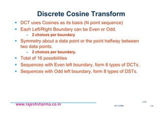
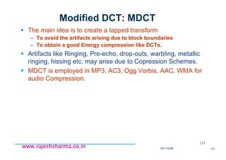
Finite Impulse Response
∑=
−=
M
k
knxkhny
0
][][][
∑=
−=
M
k
k knxbny
0
][][
Finite Impulse Response
FIR Filters
Non-Recursive
Convolution Based Implementation
)2()1()()(: 210 −+−+= nxbnxbnxbnyFIR
The impulse response vanish
after finite number of samples](https://image.slidesharecdn.com/dspfundamentalspart-ii-180730074432/85/Dsp-fundamentals-part-ii-140-320.jpg)
![18/11/2008 141
www.rajeshsharma.co.inwww.rajeshsharma.co.inwww.rajeshsharma.co.inwww.rajeshsharma.co.in
Infinite Impulse Response
∑
∞
=
−=
0
][][][
k
knxkhny
∑∑ ==
−+−=
M
k
k
N
k
k knxbknyany
01
][][][
Infinite Impulse Response
IIR Filters
Recursive
Feedback Based Implementation
)1()()(: −+= naynxnyIIR
The impulse response does not
vanish after finite number of samples
z-1
a
x[n] y[n]
+](https://image.slidesharecdn.com/dspfundamentalspart-ii-180730074432/85/Dsp-fundamentals-part-ii-141-320.jpg)
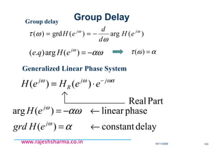
![18/11/2008 142
www.rajeshsharma.co.inwww.rajeshsharma.co.inwww.rajeshsharma.co.inwww.rajeshsharma.co.in
][*][][ nhnxny = )()()( zHzXzY =
)(
|)(|)(
ω
ωω j
eHjjj
eeHeH ∠
⋅=
(e.q) Frequency selective filter - ideal
|)(| ωj
eH
cωcω− π ω
c
j
eH ωωω
<= ||,1|)(|
elsewhere,0
αωω
−=∠ )( j
eH
)(
)(sin
][
απ
αω
−
−
=
n
n
nh c
( : delay, centerpoint of sync function)α
1
Frequency Response
)( ωj
eH∠
π ω
α−](https://image.slidesharecdn.com/dspfundamentalspart-ii-180730074432/85/Dsp-fundamentals-part-ii-142-320.jpg)
![18/11/2008 145
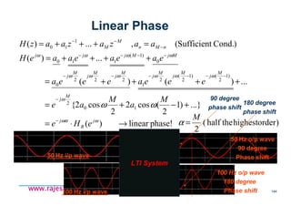
www.rajeshsharma.co.inwww.rajeshsharma.co.inwww.rajeshsharma.co.inwww.rajeshsharma.co.in
∑∑ ==
−+−=
M
k
k
N
k
k knxbknyany
01
][][][
∑
∑
=
−
=
−
−
= N
k
k
k
M
k
k
k
za
zb
zH
1
0
1
)(
(1) Direct Form-I
)(nx )(ny
1−
z
1−
z
1−
z
1−
z
1−
z
1−
z
)1( −nx
)1( +− Mnx
)( Mnx −
0b
1b
1−Mb
Mb )( Nny −
)1( +− Nny
)1( −ny
1a
1−Na
Na
IIR filter Structure](https://image.slidesharecdn.com/dspfundamentalspart-ii-180730074432/85/Dsp-fundamentals-part-ii-145-320.jpg)
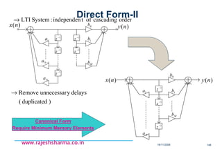
![18/11/2008 165
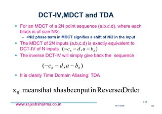
www.rajeshsharma.co.inwww.rajeshsharma.co.inwww.rajeshsharma.co.inwww.rajeshsharma.co.in
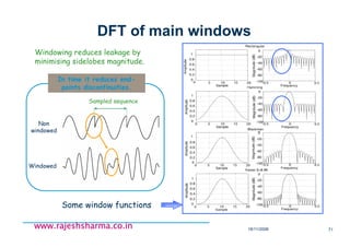
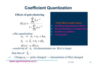
Y(n) = ay(n-1) - x(n) -> y(n) = Q[ay(n-1)] - x(n)
x[n] y[n]
z-1
x[n]
y[n]
z-1Q[]
a
a
Limit Cycle
Magnitude truncation can be used
to eliminate limit cycles
Eventually decays Oscillations
Dead
Band](https://image.slidesharecdn.com/dspfundamentalspart-ii-180730074432/85/Dsp-fundamentals-part-ii-165-320.jpg)


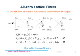
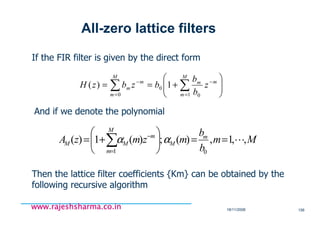
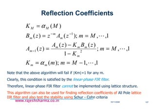
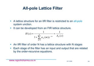
![Digital Signal Processing[ECEG-3171]-Ch1_L05](https://cdn.slidesharecdn.com/ss_thumbnails/dspl5ch2-180427094424-thumbnail.jpg?width=640&height=640&fit=bounds)


![Introduction to Signal Processing Orfanidis [Solution Manual]](https://cdn.slidesharecdn.com/ss_thumbnails/51628783-solution-signal-processing-160422182740-thumbnail.jpg?width=640&height=640&fit=bounds)


