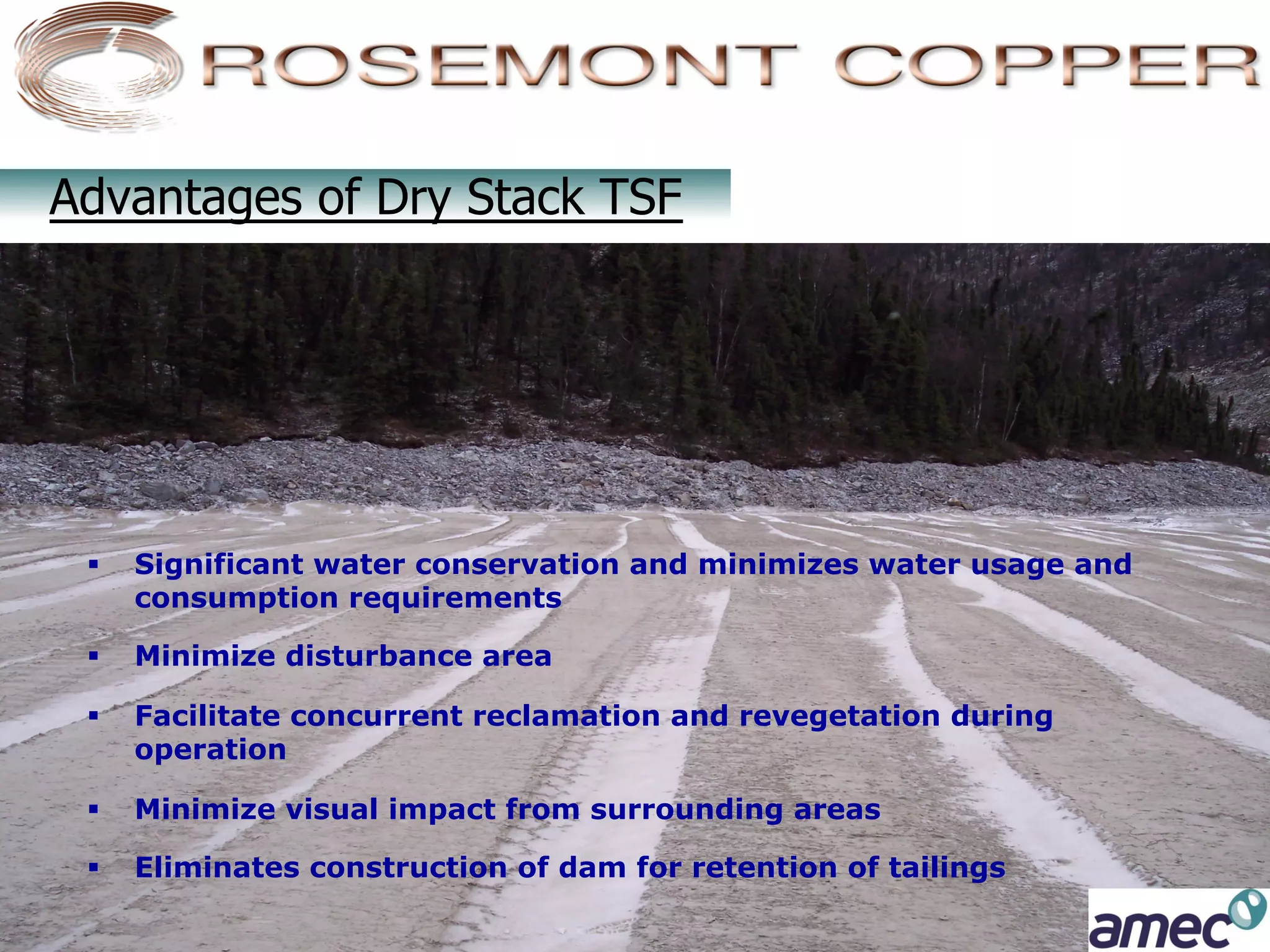
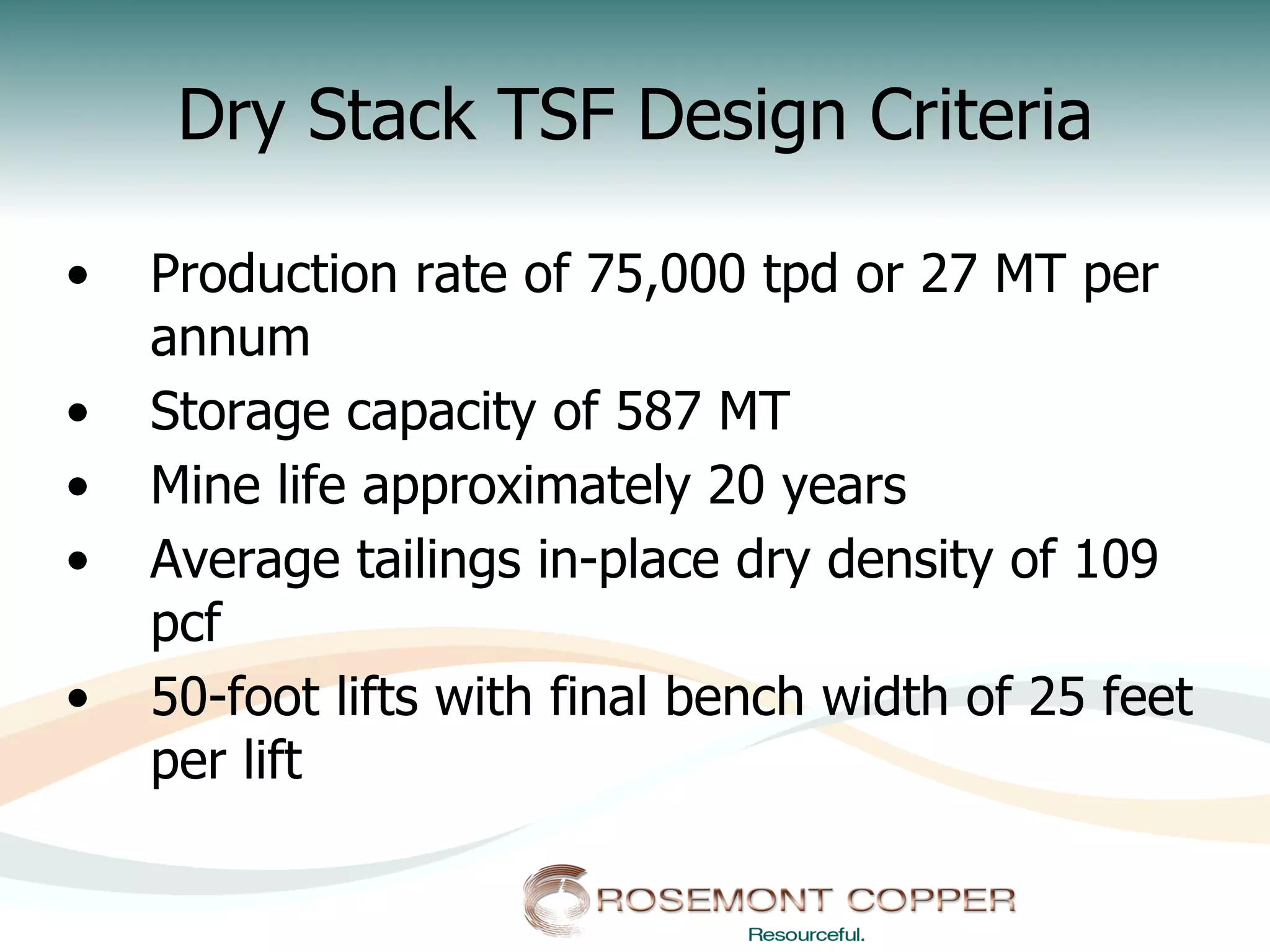
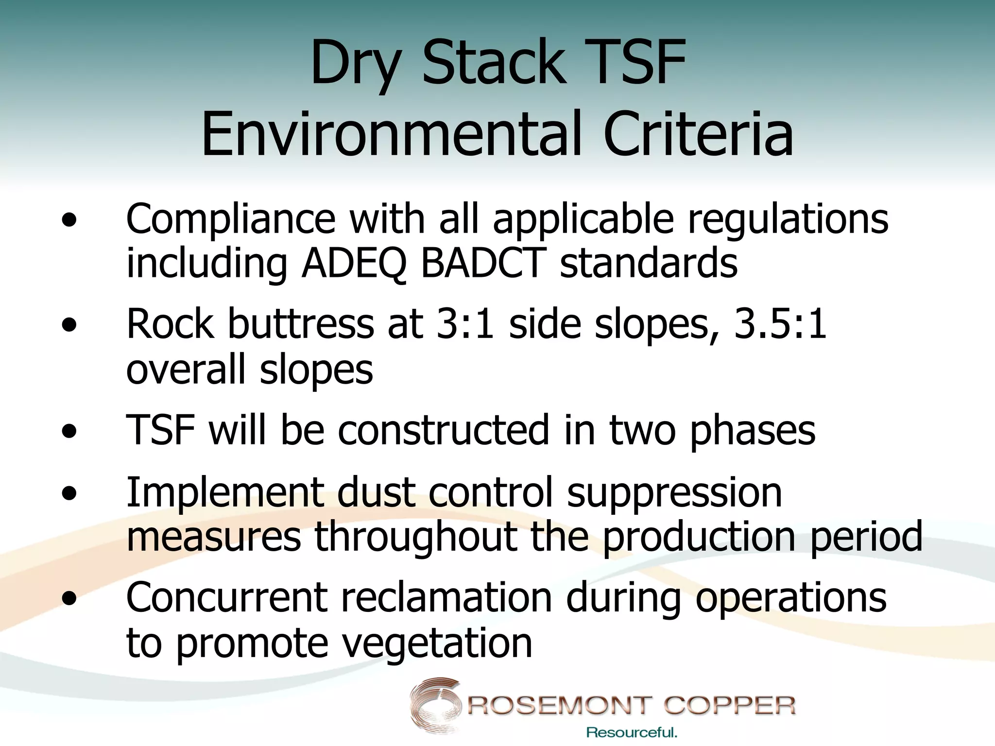
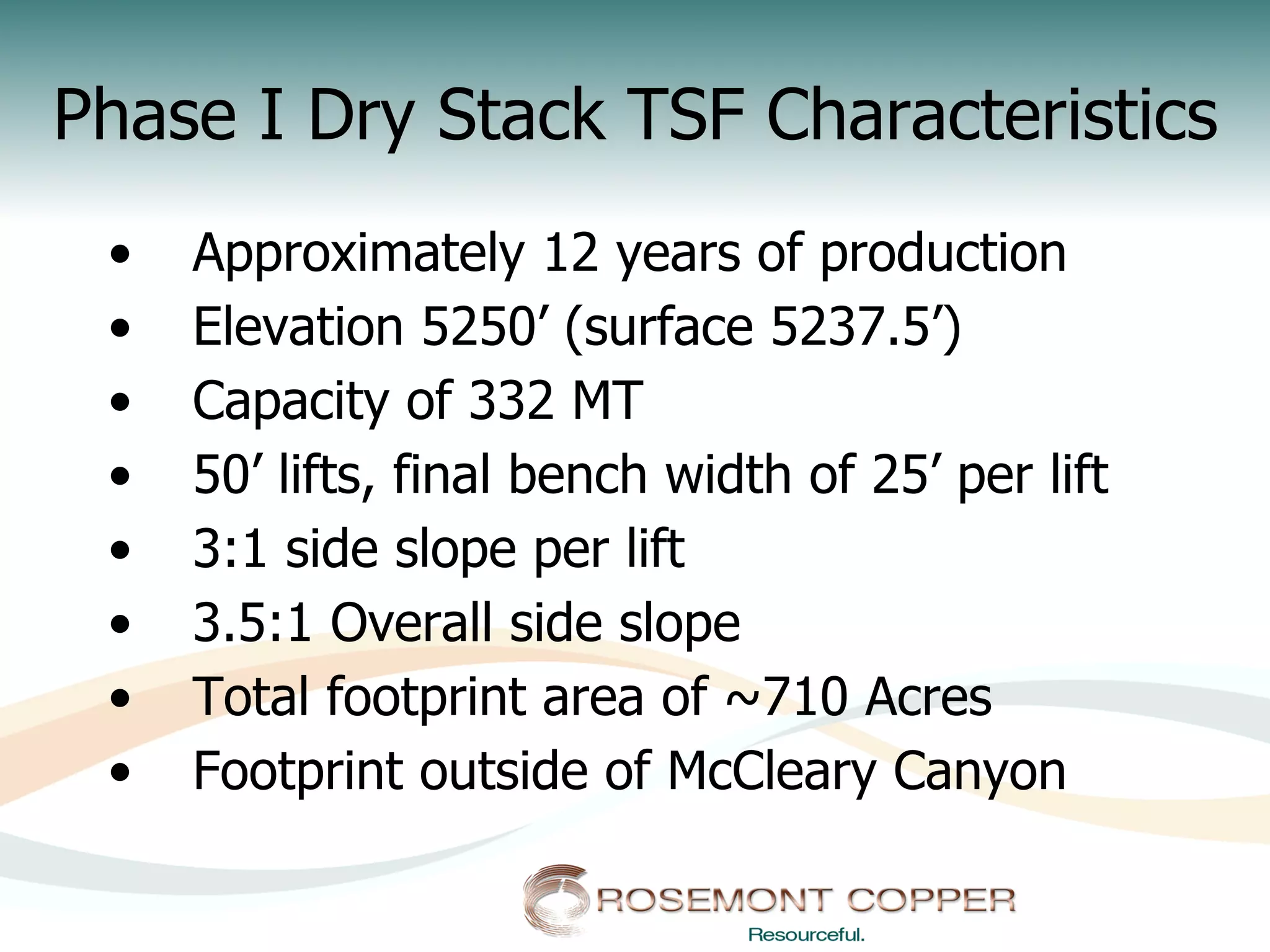
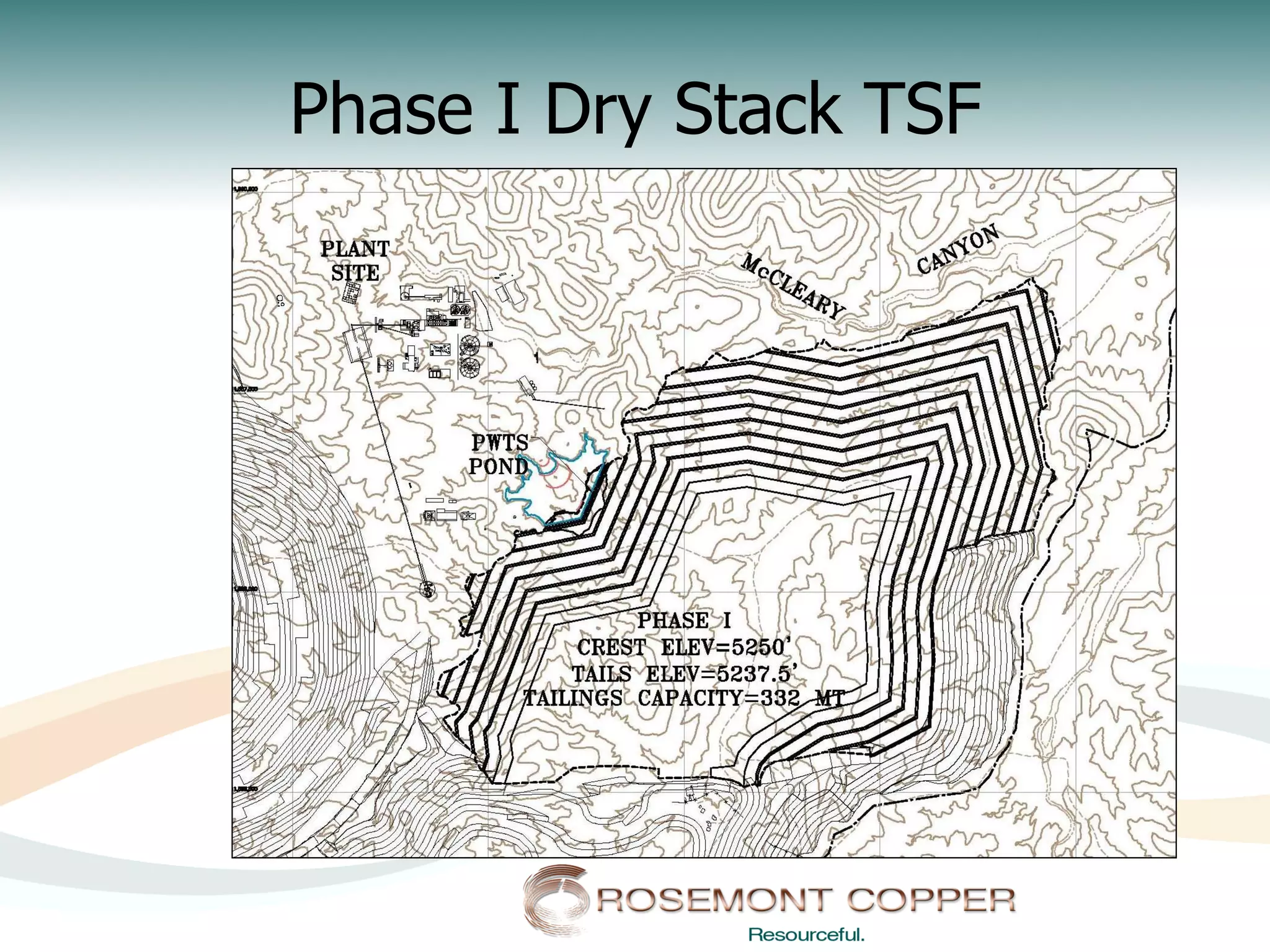
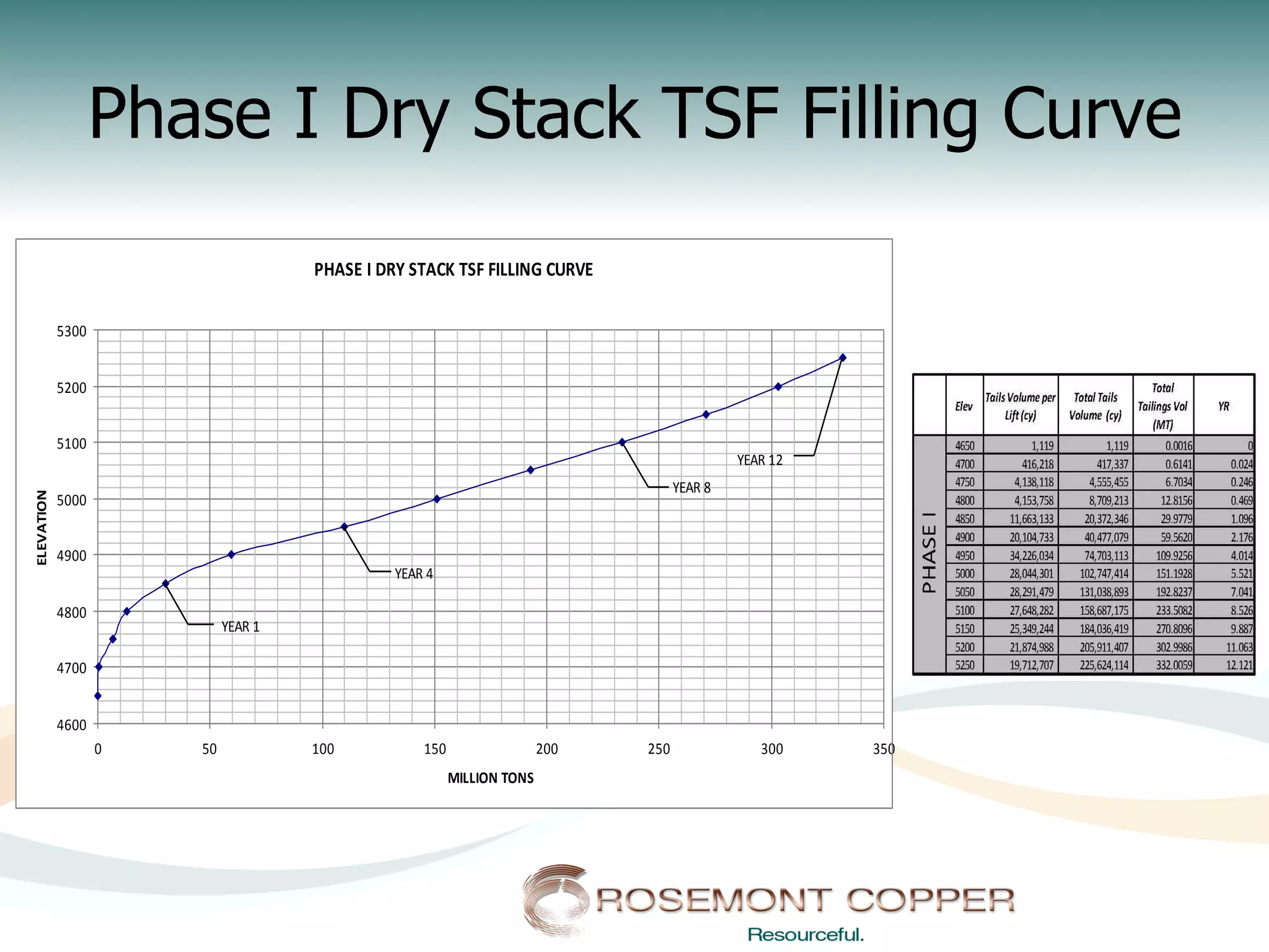
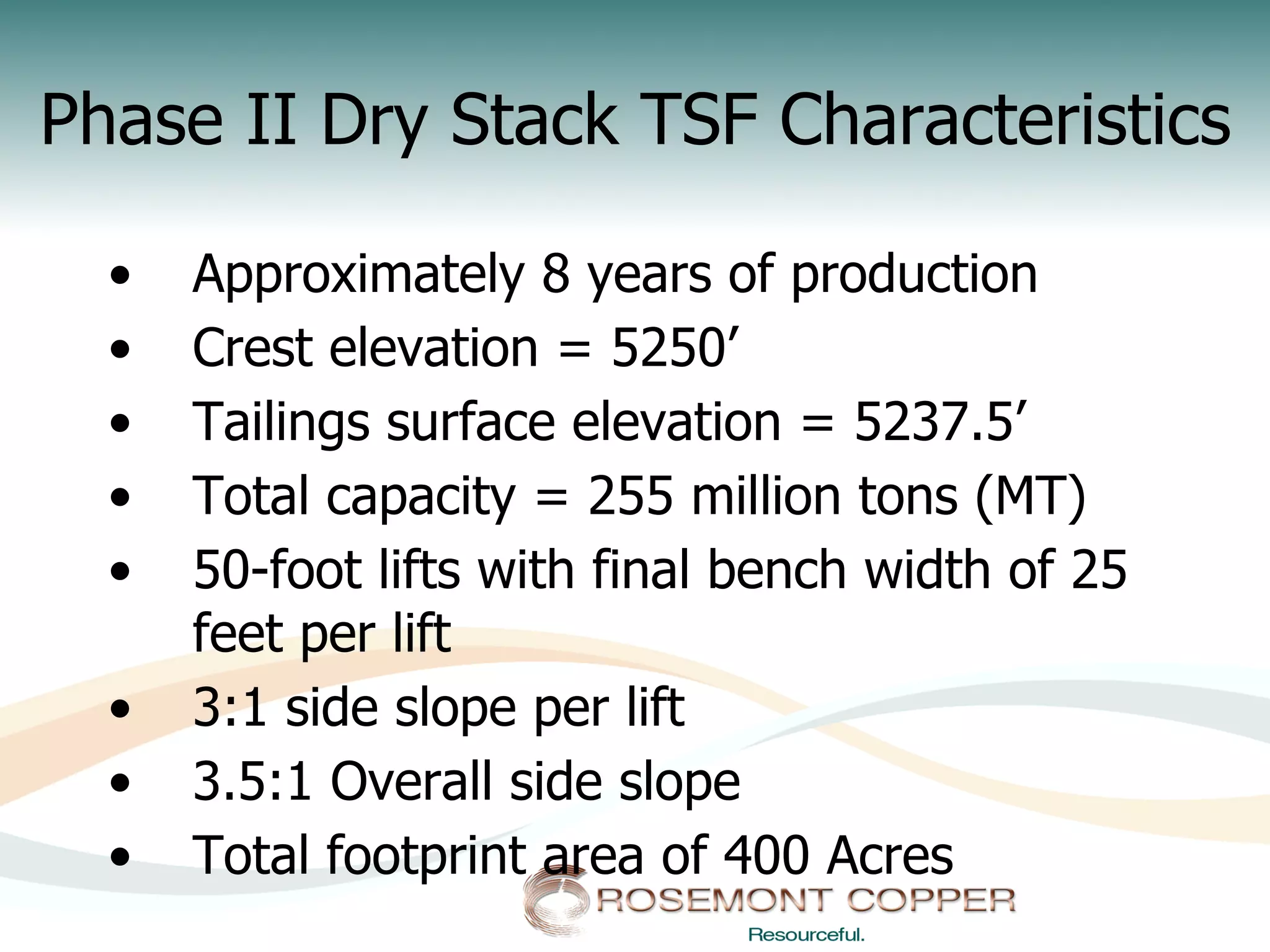
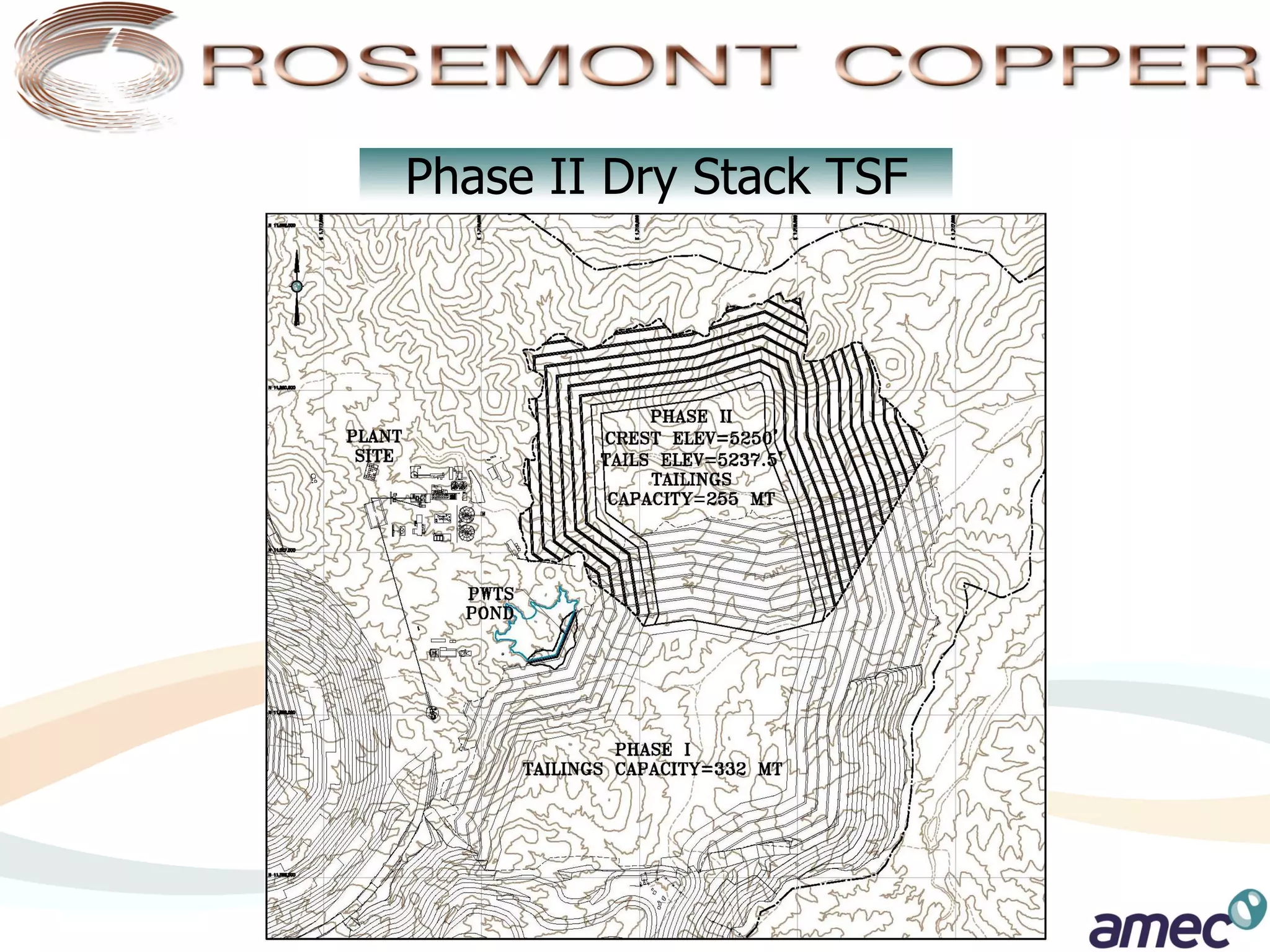
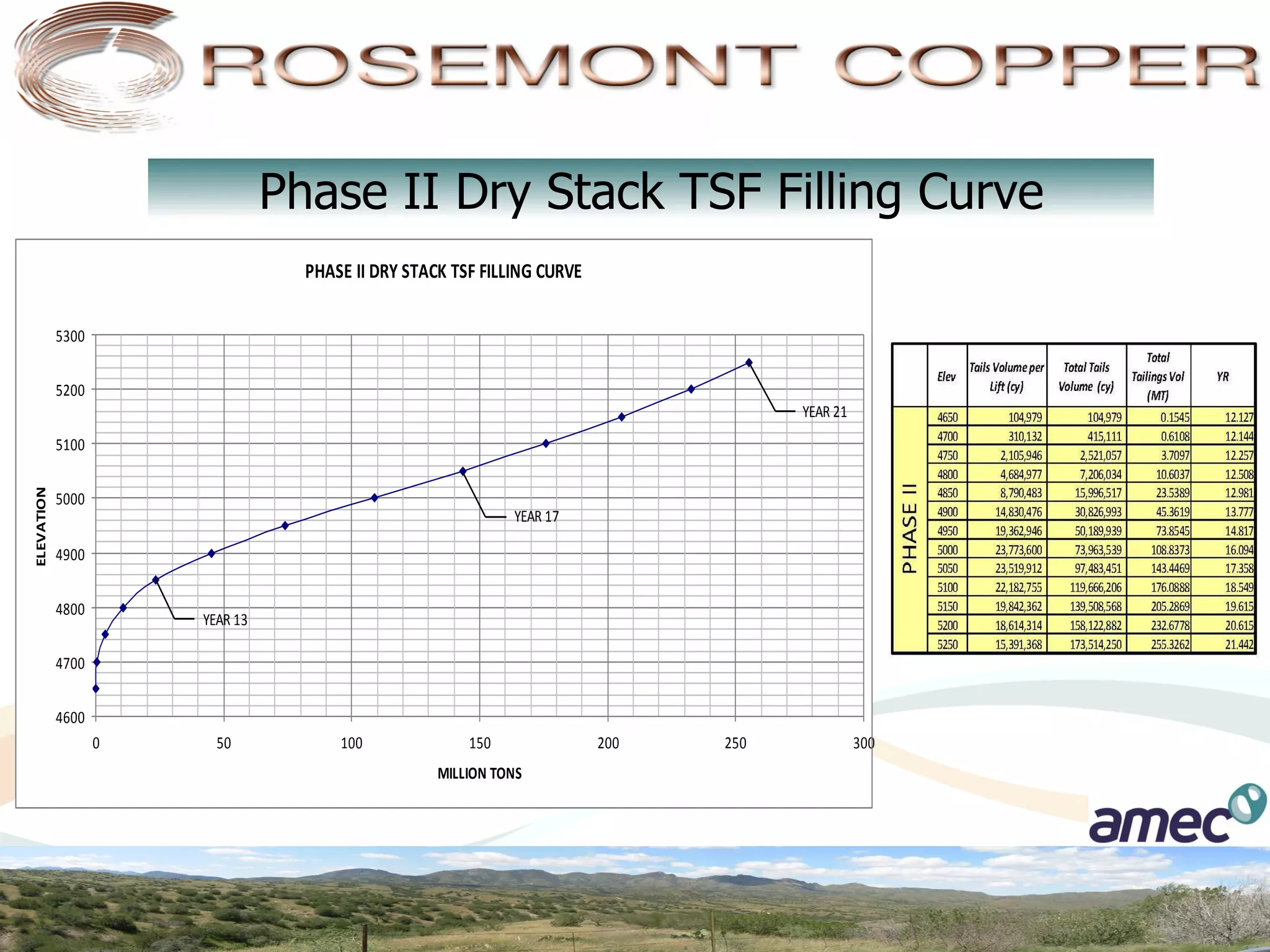
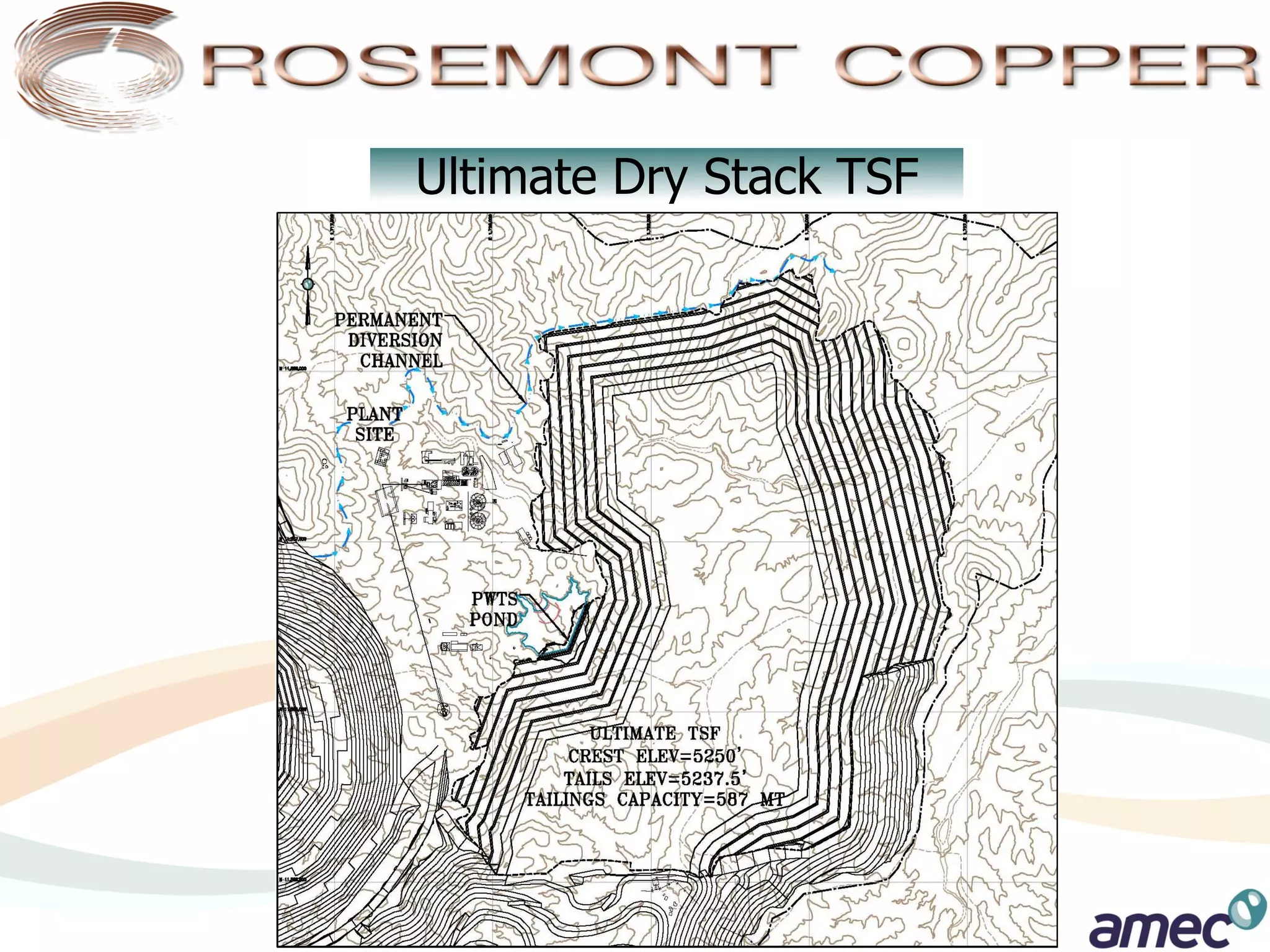
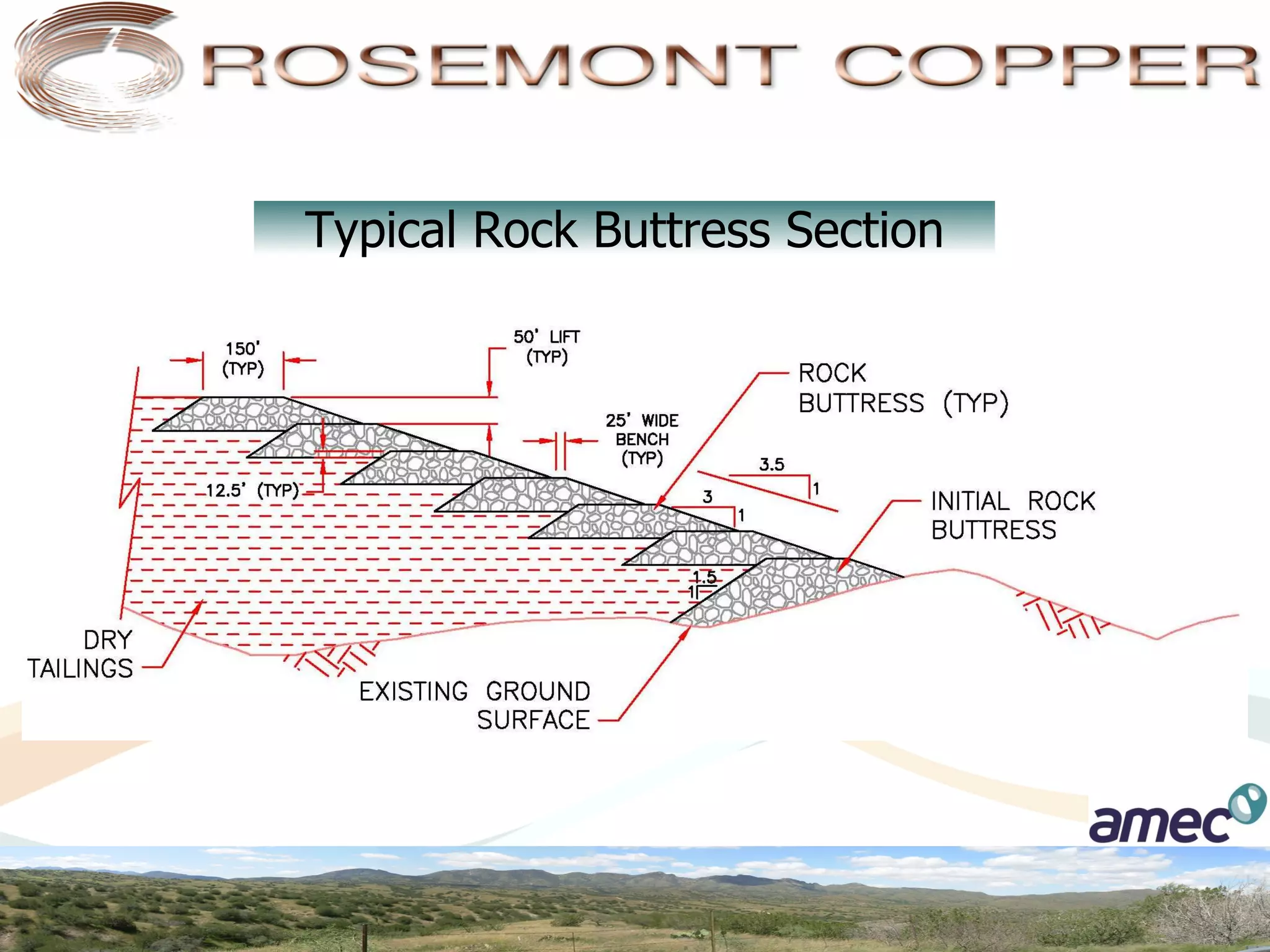
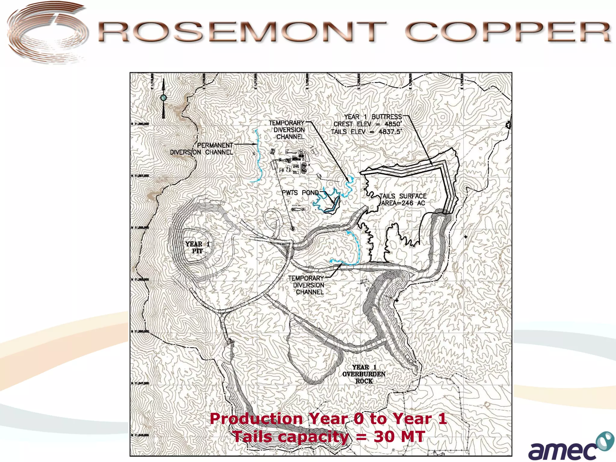
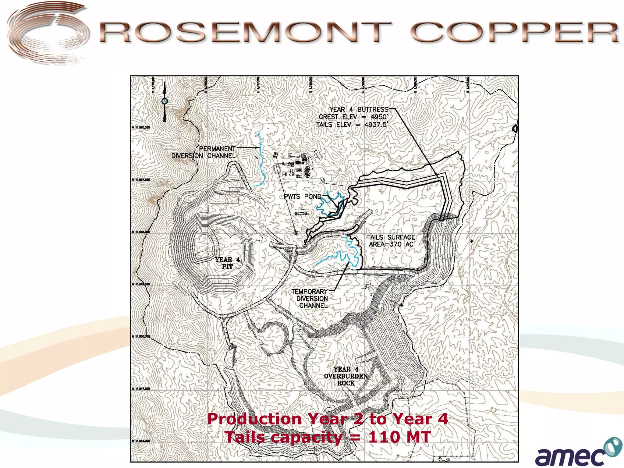
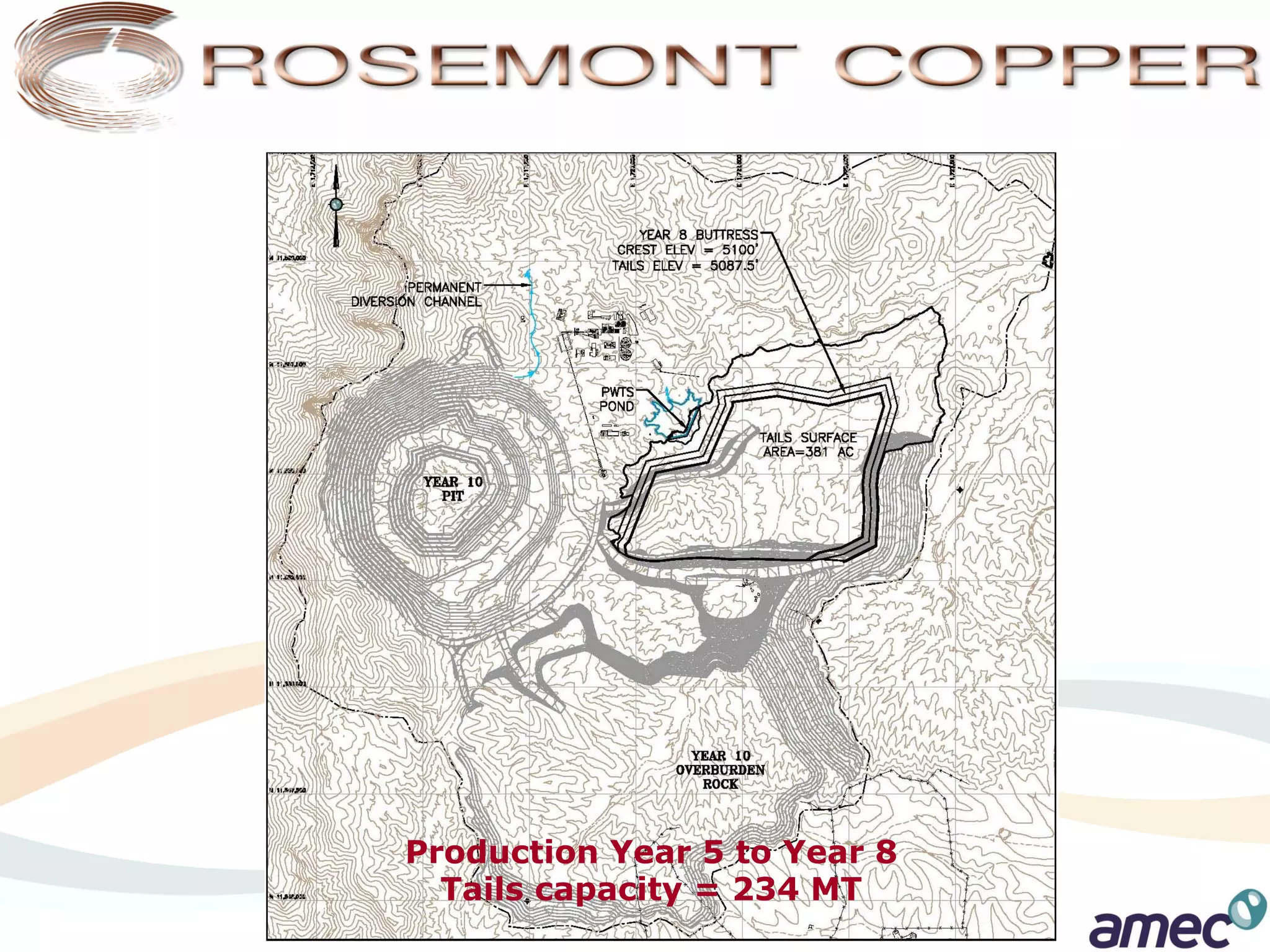
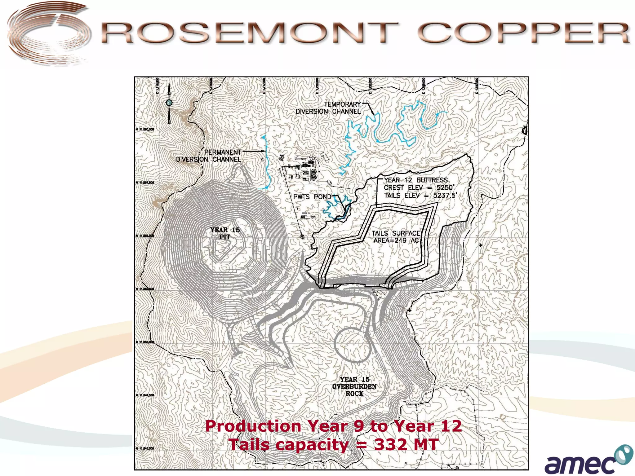
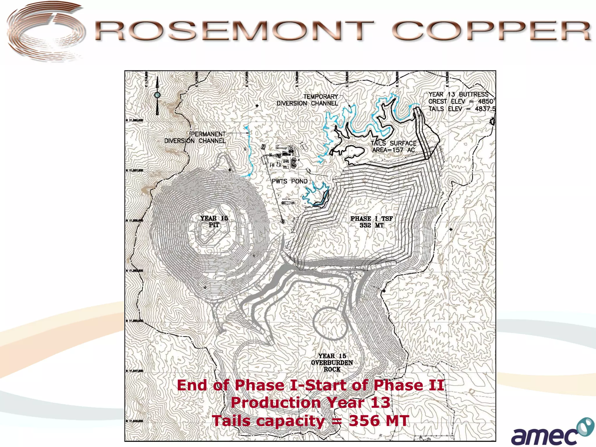
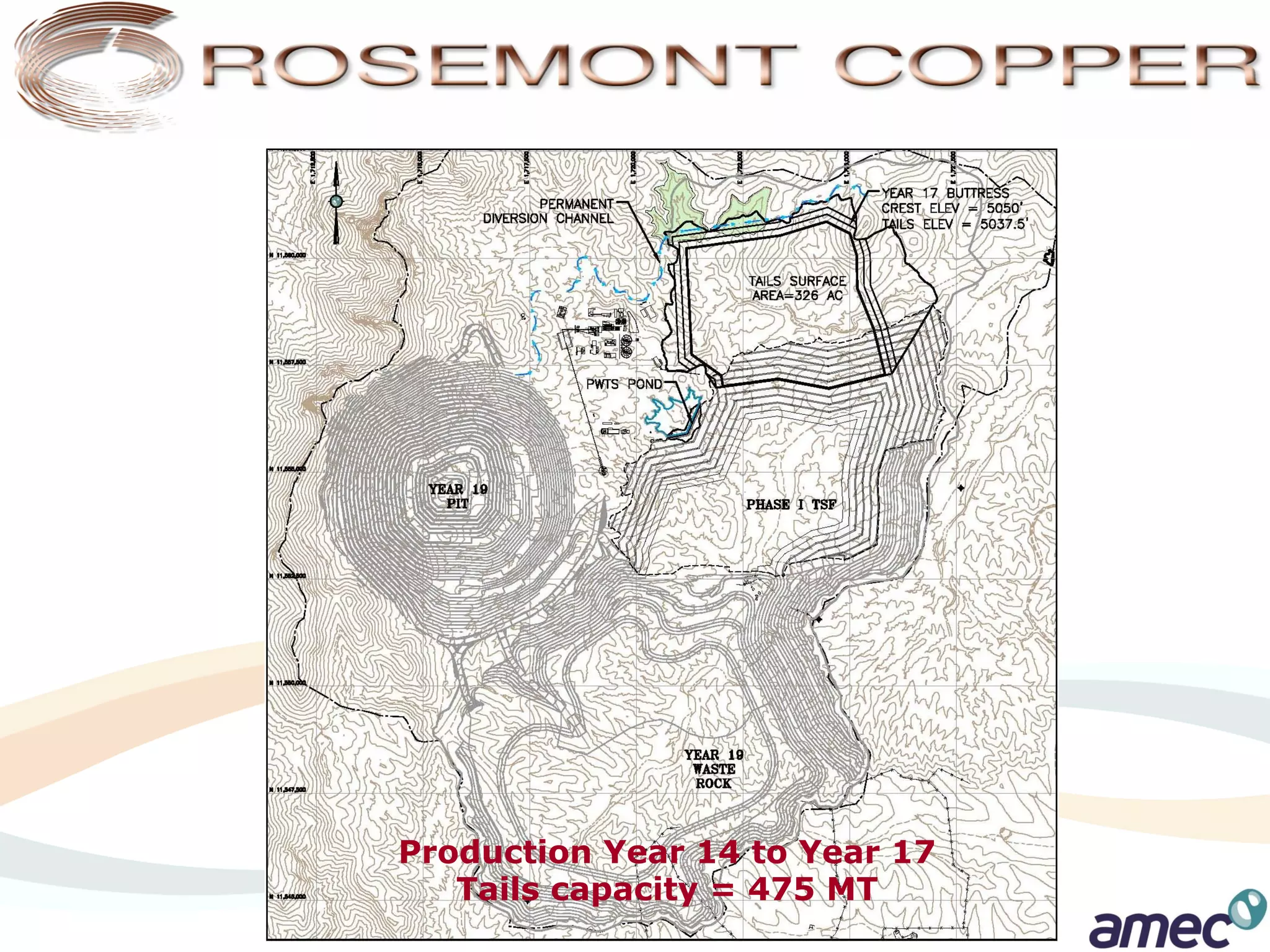
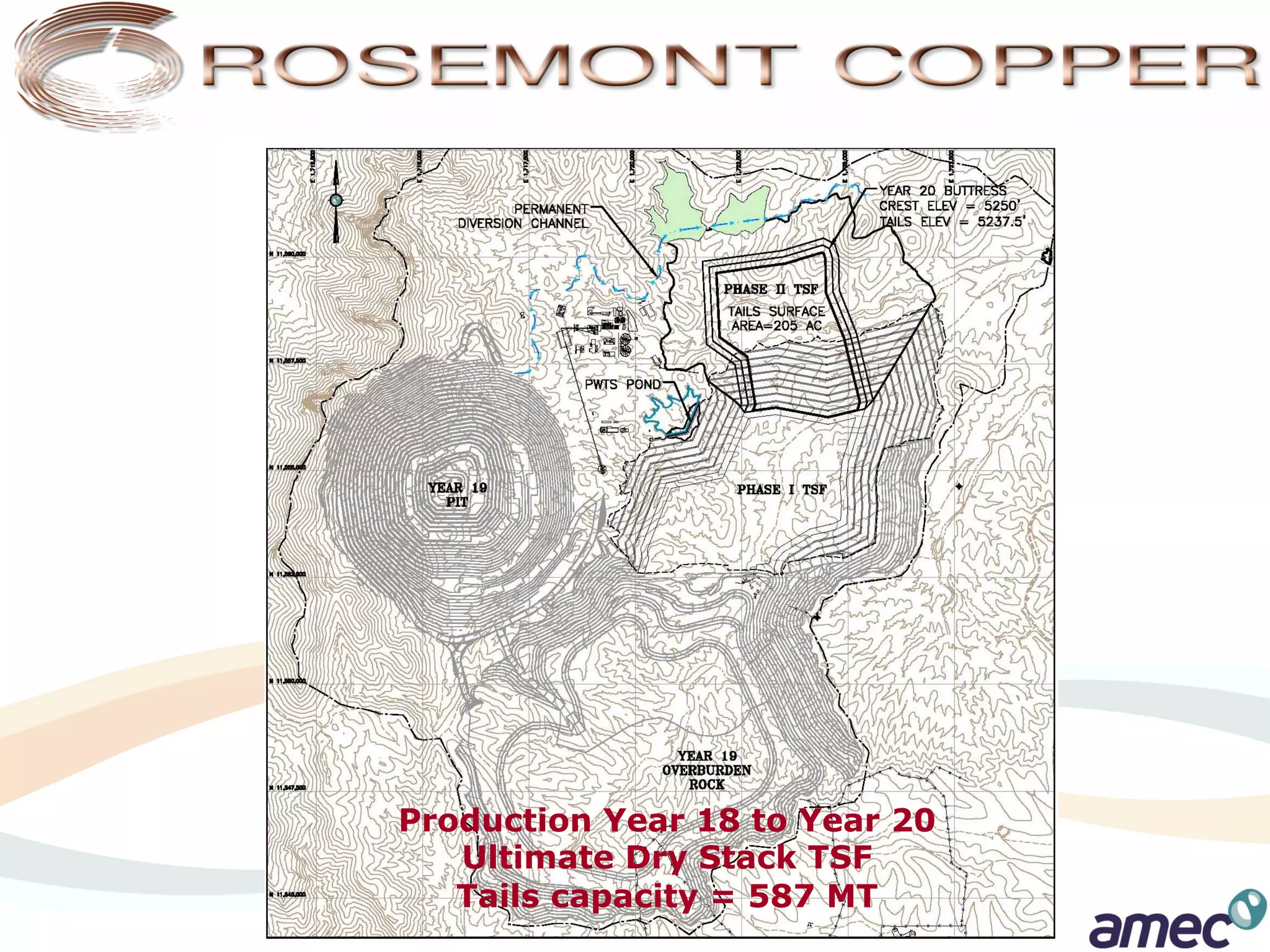
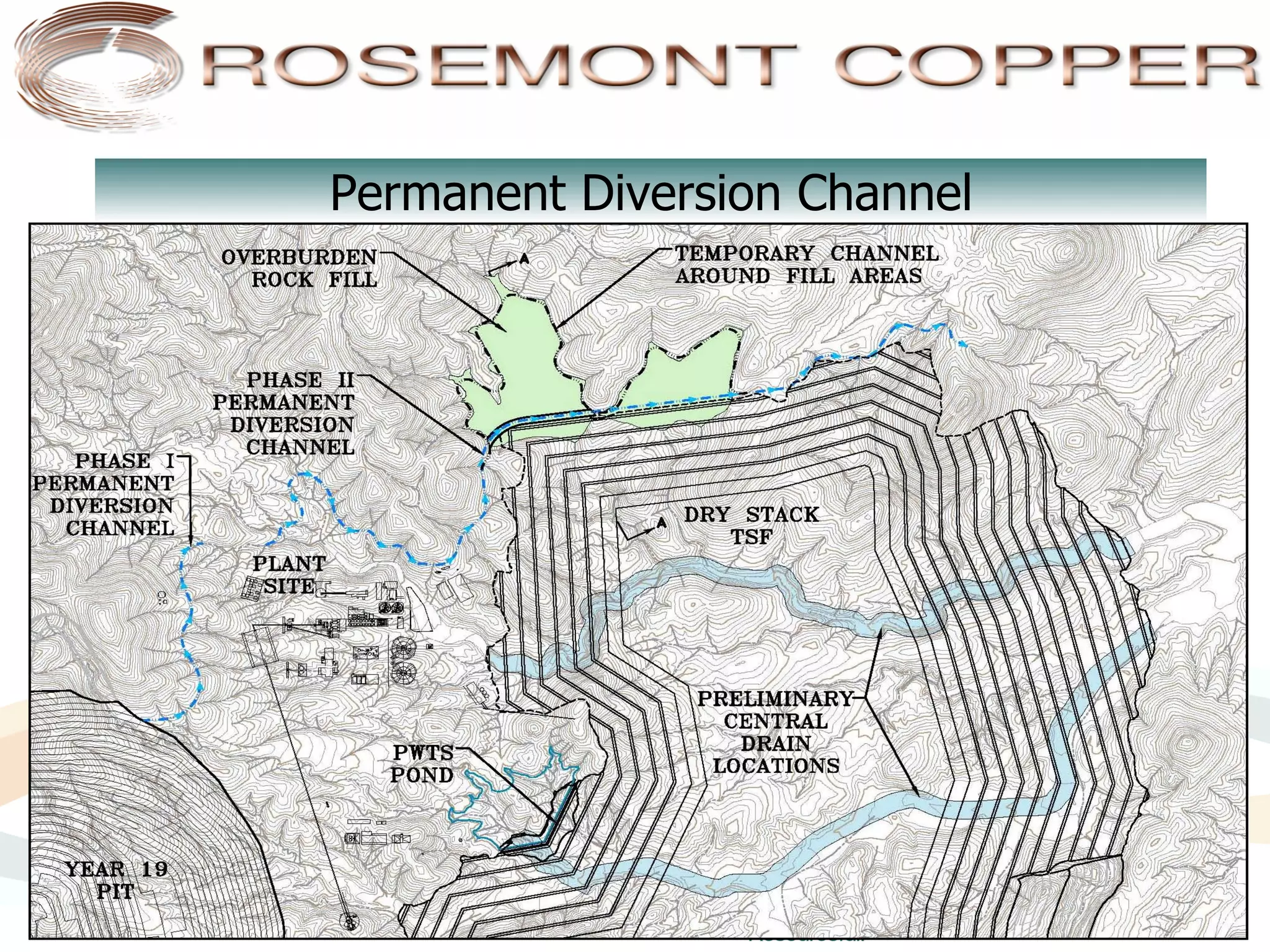
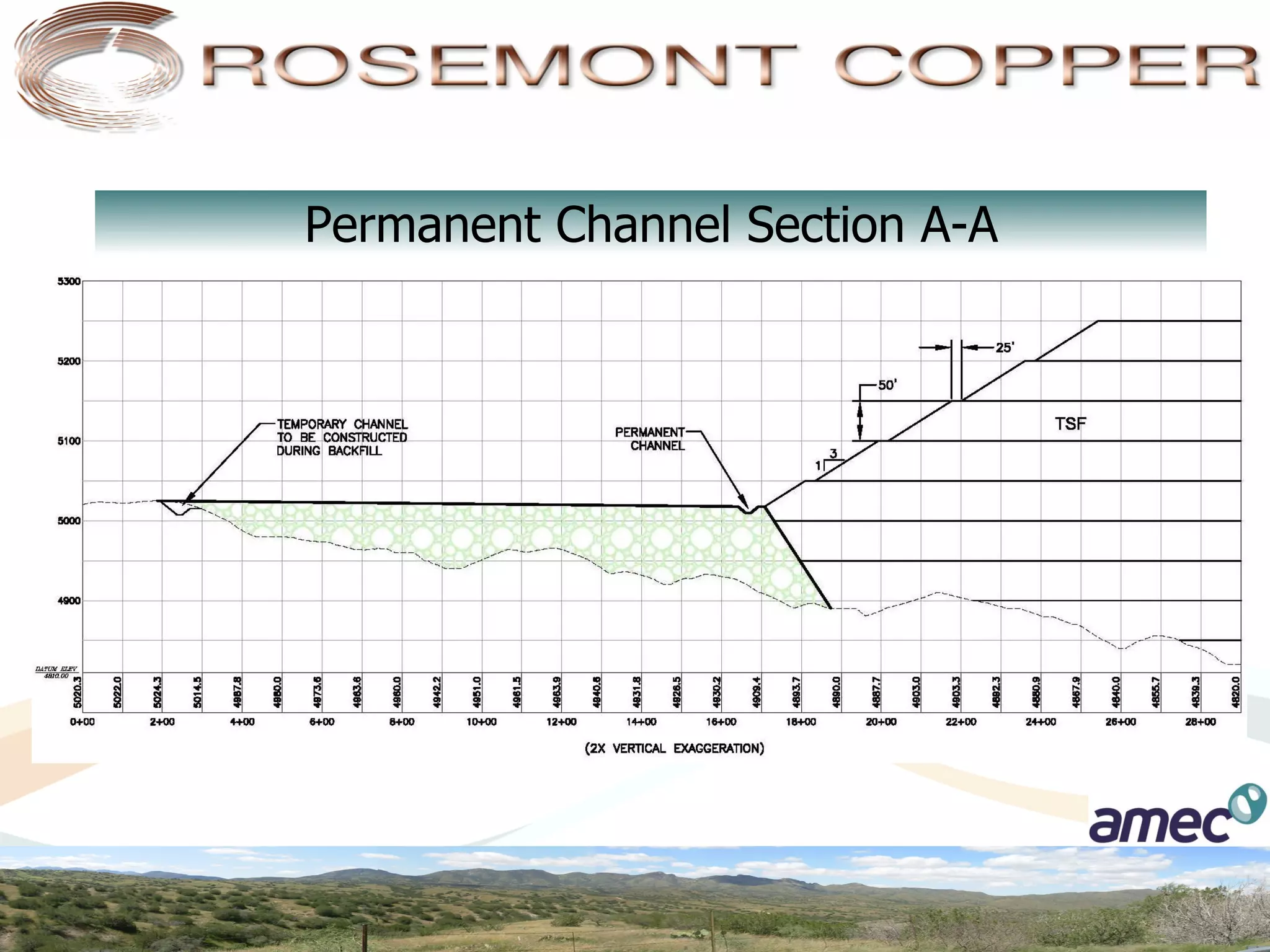
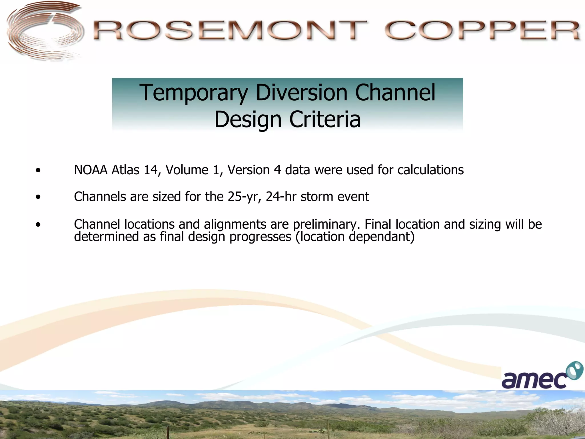
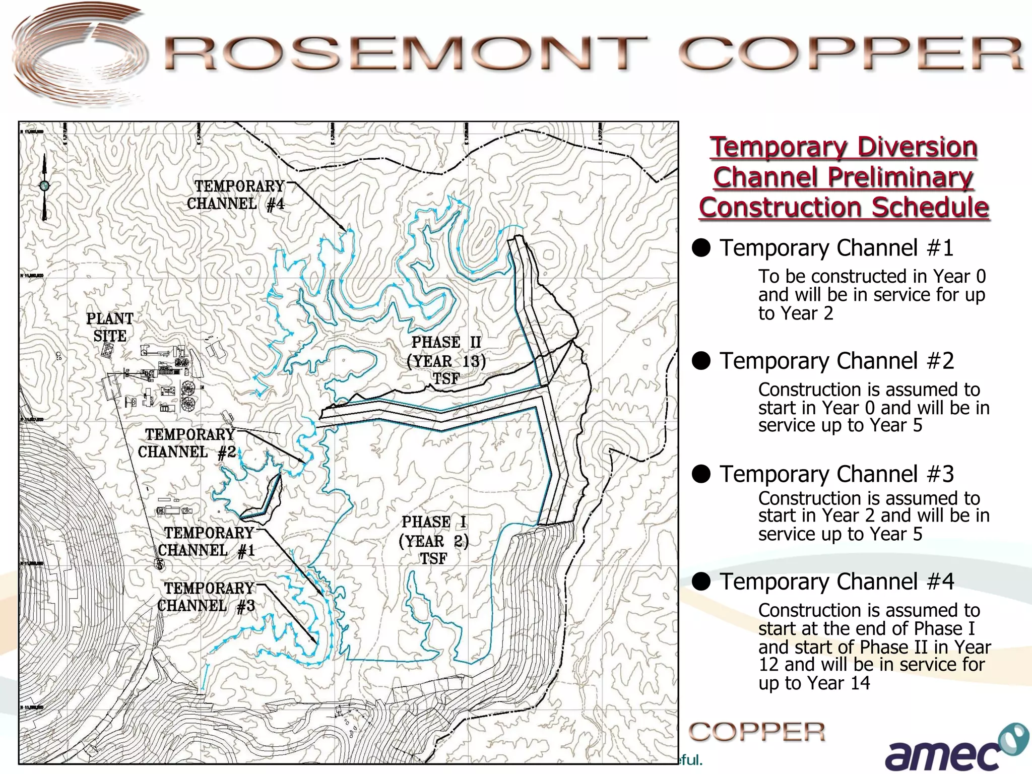
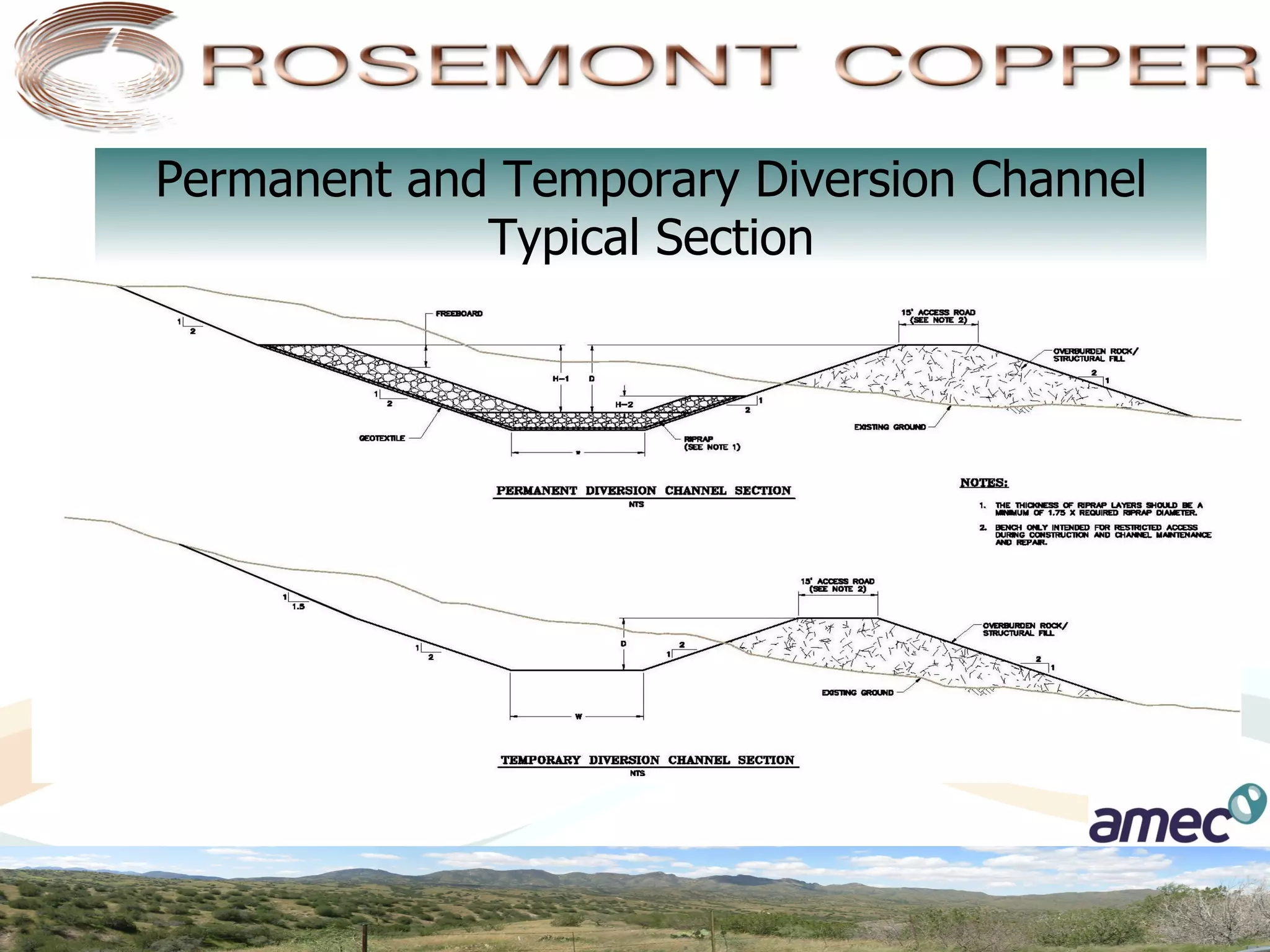
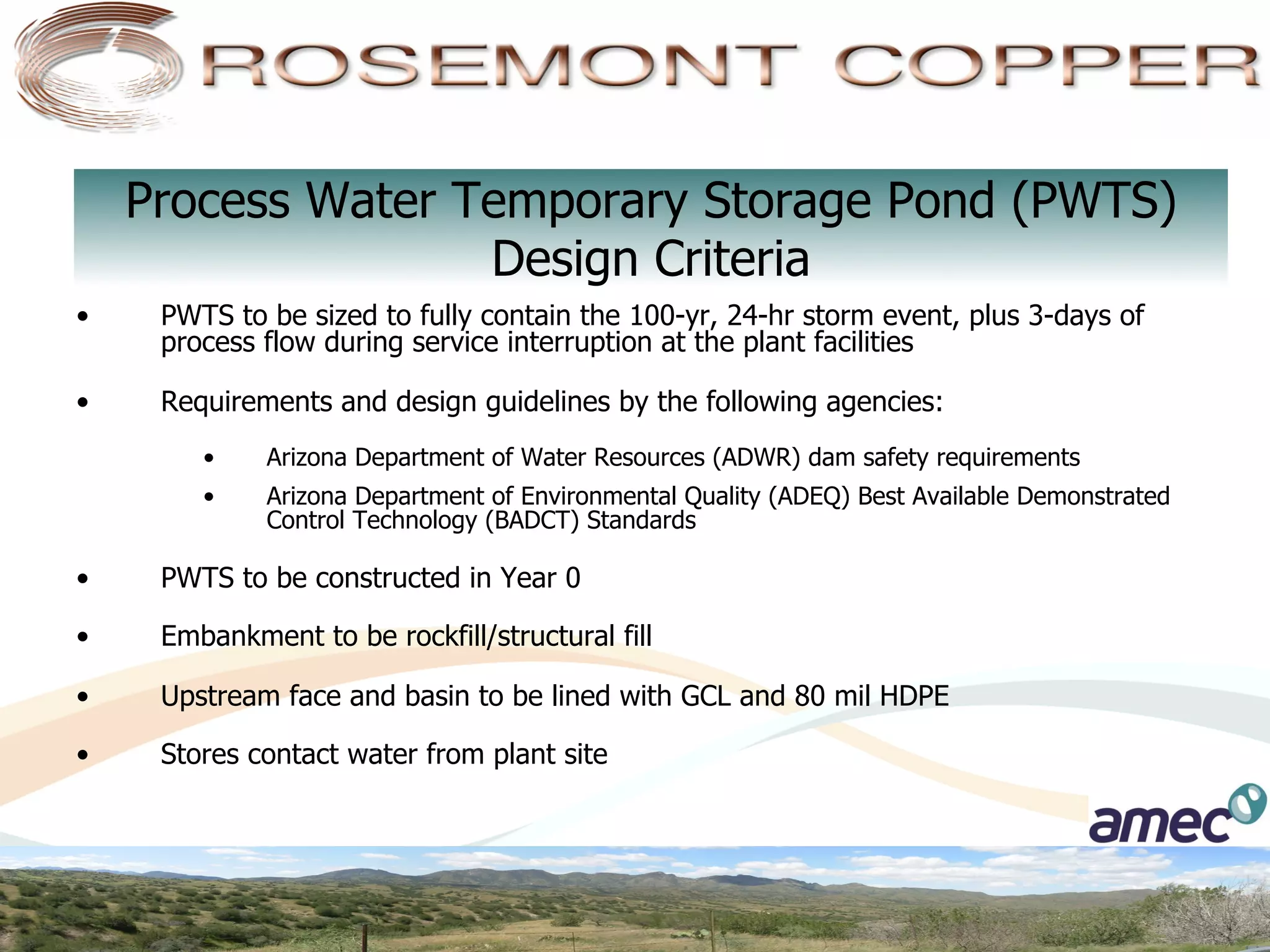
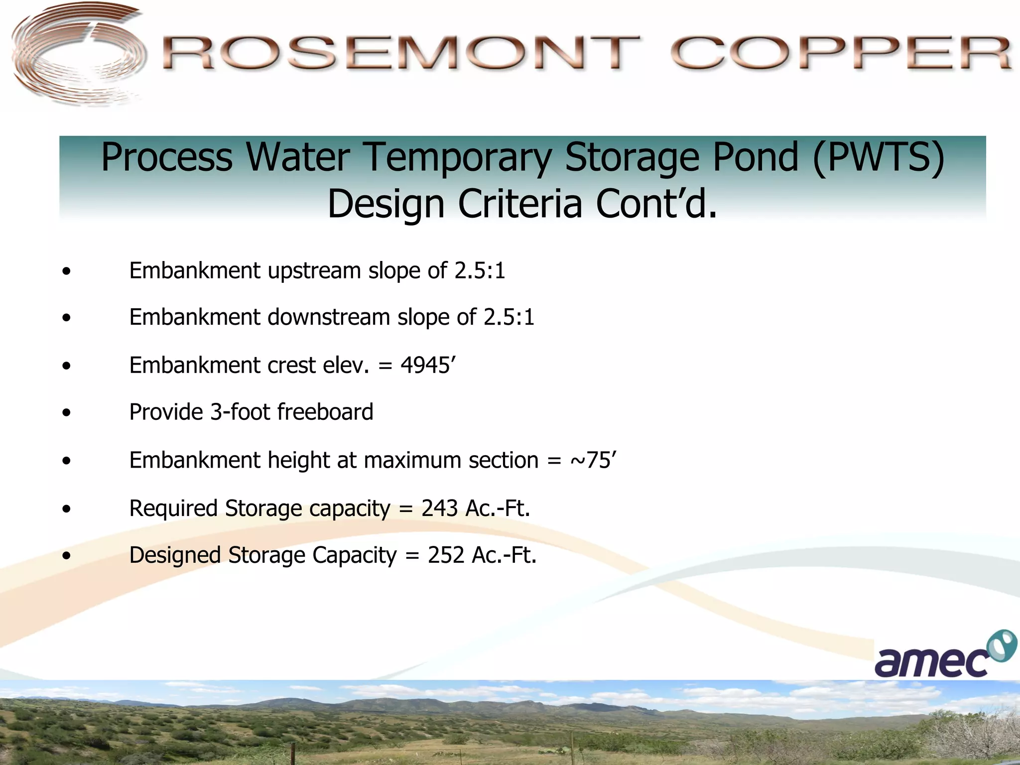
Dry Stack
Tailings Storage Facility
Advantages of Dry Stack TSF


 §    Significant water conservation and minimizes water usage and
       consumption requirements

 §    Minimize disturbance area

 §    Facilitate concurrent reclamation and revegetation during
       operation

 §    Minimize visual impact from surrounding areas

 §    Eliminates construction of dam for retention of tailings
Dry Stack TSF Design Criteria

•    Production rate of 75,000 tpd or 27 MT per
     annum
•    Storage capacity of 587 MT
•    Mine life approximately 20 years
•    Average tailings in-place dry density of 109
     pcf
•    50-foot lifts with final bench width of 25 feet
     per lift
Dry Stack TSF
        Environmental Criteria
•    Compliance with all applicable regulations
     including ADEQ BADCT standards
•    Rock buttress at 3:1 side slopes, 3.5:1
     overall slopes
•    TSF will be constructed in two phases
•    Implement dust control suppression
     measures throughout the production period
•    Concurrent reclamation during operations
     to promote vegetation
Phase I Dry Stack TSF Characteristics
 •    Approximately 12 years of production
 •    Elevation 5250’ (surface 5237.5’)
 •    Capacity of 332 MT
 •    50’ lifts, final bench width of 25’ per lift
 •    3:1 side slope per lift
 •    3.5:1 Overall side slope
 •    Total footprint area of ~710 Acres
 •    Footprint outside of McCleary Canyon
Phase I Dry Stack TSF
Phase I Dry Stack TSF Filling Curve
                                        PHASE	
  I	
  DRY	
  STACK	
  TSF	
  FILLING	
  CURVE

            5300


            5200


            5100
                                                                                                                  YEAR	
  12
                                                                                                      YEAR	
  8
ELEVATION


            5000


            4900
                                                       YEAR	
  4

            4800
                            YEAR	
  1

            4700


            4600
                   0   50               100                  150                     200        250                    300     350
                                                                   MILLION	
  TONS
Phase II Dry Stack TSF Characteristics

  •    Approximately 8 years of production
  •    Crest elevation = 5250’
  •    Tailings surface elevation = 5237.5’
  •    Total capacity = 255 million tons (MT)
  •    50-foot lifts with final bench width of 25
       feet per lift
  •    3:1 side slope per lift
  •    3.5:1 Overall side slope
  •    Total footprint area of 400 Acres
Phase II Dry Stack TSF
Phase II Dry Stack TSF Filling Curve
                                      PHASE	
  II	
  DRY	
  STACK	
  TSF	
  FILLING	
  CURVE


            5300


            5200
                                                                                                           YEAR	
  21
            5100
ELEVATION


            5000
                                                                              YEAR	
  17

            4900


            4800
                       YEAR	
  13

            4700


            4600
                   0      50                100                       150                      200   250                300
                                                               MILLION	
  TONS
Ultimate Dry Stack TSF
Typical Rock Buttress Section
Dry Stack TSF
Stacking Progression
Production Year 0 to Year 1
  Tails capacity = 30 MT
Production Year 2 to Year 4
  Tails capacity = 110 MT
Production Year 5 to Year 8
  Tails capacity = 234 MT
Production Year 9 to Year 12
  Tails capacity = 332 MT
End of Phase I-Start of Phase II
      Production Year 13
    Tails capacity = 356 MT
Production Year 14 to Year 17
   Tails capacity = 475 MT
Production Year 18 to Year 20
   Ultimate Dry Stack TSF
   Tails capacity = 587 MT
Permanent Diversion Channel
                        Design Criteria
n    NOAA Atlas 14, Volume 1, Version 4 data were used for calculations

n    Channels are sized for the 200-yr, 24-hr storm event

n    Channels are assumed to be in rock for the majority of the length. Riprap
      will be provided in areas of fill

n    A 15-foot wide access road will be constructed adjacent to the channel on
      the downstream side to allow access for maintenance and repair
      purposes only
Permanent Diversion Channel
Permanent Channel Section A-A
Temporary Diversion Channel
                      Design Criteria

•    NOAA Atlas 14, Volume 1, Version 4 data were used for calculations

•    Channels are sized for the 25-yr, 24-hr storm event

•    Channel locations and alignments are preliminary. Final location and sizing will be
     determined as final design progresses (location dependant)
Temporary Diversion
 Channel Preliminary
Construction Schedule
● Temporary Channel #1
     To be constructed in Year 0
     and will be in service for up
     to Year 2

● Temporary Channel #2
     Construction is assumed to
     start in Year 0 and will be in
     service up to Year 5

● Temporary Channel #3
     Construction is assumed to
     start in Year 2 and will be in
     service up to Year 5

● Temporary Channel #4
     Construction is assumed to
     start at the end of Phase I
     and start of Phase II in Year
     12 and will be in service for
     up to Year 14
Permanent and Temporary Diversion Channel
             Typical Section
Process Water
Temporary Storage Pond
       (PWTS)
Process Water Temporary Storage Pond (PWTS)
                    Design Criteria
•     PWTS to be sized to fully contain the 100-yr, 24-hr storm event, plus 3-days of
      process flow during service interruption at the plant facilities

•     Requirements and design guidelines by the following agencies:
         •    Arizona Department of Water Resources (ADWR) dam safety requirements
         •    Arizona Department of Environmental Quality (ADEQ) Best Available Demonstrated
              Control Technology (BADCT) Standards

•     PWTS to be constructed in Year 0

•     Embankment to be rockfill/structural fill

•     Upstream face and basin to be lined with GCL and 80 mil HDPE

•     Stores contact water from plant site
Process Water Temporary Storage Pond (PWTS)
                 Design Criteria Cont’d.
•     Embankment upstream slope of 2.5:1

•     Embankment downstream slope of 2.5:1

•     Embankment crest elev. = 4945’

•     Provide 3-foot freeboard

•     Embankment height at maximum section = ~75’

•     Required Storage capacity = 243 Ac.-Ft.

•     Designed Storage Capacity = 252 Ac.-Ft.
PWTS Plan View
PWTS Embankment Volume                 227,384   cy (Fill)


Regrading at Pond Basin (Cut Volume)   237,225   cy (Cut)


PWTS Basin Volume @ El = 4942'             252   Ac.-Ft.

Dry Stack Tailings Facility

  • 1.
  • 2.
    Advantages of DryStack TSF §  Significant water conservation and minimizes water usage and consumption requirements §  Minimize disturbance area §  Facilitate concurrent reclamation and revegetation during operation §  Minimize visual impact from surrounding areas §  Eliminates construction of dam for retention of tailings
  • 3.
    Dry Stack TSFDesign Criteria •  Production rate of 75,000 tpd or 27 MT per annum •  Storage capacity of 587 MT •  Mine life approximately 20 years •  Average tailings in-place dry density of 109 pcf •  50-foot lifts with final bench width of 25 feet per lift
  • 4.
    Dry Stack TSF Environmental Criteria •  Compliance with all applicable regulations including ADEQ BADCT standards •  Rock buttress at 3:1 side slopes, 3.5:1 overall slopes •  TSF will be constructed in two phases •  Implement dust control suppression measures throughout the production period •  Concurrent reclamation during operations to promote vegetation
  • 5.
    Phase I DryStack TSF Characteristics •  Approximately 12 years of production •  Elevation 5250’ (surface 5237.5’) •  Capacity of 332 MT •  50’ lifts, final bench width of 25’ per lift •  3:1 side slope per lift •  3.5:1 Overall side slope •  Total footprint area of ~710 Acres •  Footprint outside of McCleary Canyon
  • 6.
    Phase I DryStack TSF
  • 7.
    Phase I DryStack TSF Filling Curve PHASE  I  DRY  STACK  TSF  FILLING  CURVE 5300 5200 5100 YEAR  12 YEAR  8 ELEVATION 5000 4900 YEAR  4 4800 YEAR  1 4700 4600 0 50 100 150 200 250 300 350 MILLION  TONS
  • 8.
    Phase II DryStack TSF Characteristics •  Approximately 8 years of production •  Crest elevation = 5250’ •  Tailings surface elevation = 5237.5’ •  Total capacity = 255 million tons (MT) •  50-foot lifts with final bench width of 25 feet per lift •  3:1 side slope per lift •  3.5:1 Overall side slope •  Total footprint area of 400 Acres
  • 9.
    Phase II DryStack TSF
  • 10.
    Phase II DryStack TSF Filling Curve PHASE  II  DRY  STACK  TSF  FILLING  CURVE 5300 5200 YEAR  21 5100 ELEVATION 5000 YEAR  17 4900 4800 YEAR  13 4700 4600 0 50 100 150 200 250 300 MILLION  TONS
  • 11.
  • 12.
  • 13.
  • 14.
    Production Year 0to Year 1 Tails capacity = 30 MT
  • 15.
    Production Year 2to Year 4 Tails capacity = 110 MT
  • 16.
    Production Year 5to Year 8 Tails capacity = 234 MT
  • 17.
    Production Year 9to Year 12 Tails capacity = 332 MT
  • 18.
    End of PhaseI-Start of Phase II Production Year 13 Tails capacity = 356 MT
  • 19.
    Production Year 14to Year 17 Tails capacity = 475 MT
  • 20.
    Production Year 18to Year 20 Ultimate Dry Stack TSF Tails capacity = 587 MT
  • 21.
  • 22.
    Permanent Diversion Channel Design Criteria n  NOAA Atlas 14, Volume 1, Version 4 data were used for calculations n  Channels are sized for the 200-yr, 24-hr storm event n  Channels are assumed to be in rock for the majority of the length. Riprap will be provided in areas of fill n  A 15-foot wide access road will be constructed adjacent to the channel on the downstream side to allow access for maintenance and repair purposes only
  • 23.
  • 24.
  • 25.
  • 26.
    Temporary Diversion Channel Design Criteria •  NOAA Atlas 14, Volume 1, Version 4 data were used for calculations •  Channels are sized for the 25-yr, 24-hr storm event •  Channel locations and alignments are preliminary. Final location and sizing will be determined as final design progresses (location dependant)
  • 27.
    Temporary Diversion ChannelPreliminary Construction Schedule ● Temporary Channel #1 To be constructed in Year 0 and will be in service for up to Year 2 ● Temporary Channel #2 Construction is assumed to start in Year 0 and will be in service up to Year 5 ● Temporary Channel #3 Construction is assumed to start in Year 2 and will be in service up to Year 5 ● Temporary Channel #4 Construction is assumed to start at the end of Phase I and start of Phase II in Year 12 and will be in service for up to Year 14
  • 28.
    Permanent and TemporaryDiversion Channel Typical Section
  • 29.
  • 30.
    Process Water TemporaryStorage Pond (PWTS) Design Criteria •  PWTS to be sized to fully contain the 100-yr, 24-hr storm event, plus 3-days of process flow during service interruption at the plant facilities •  Requirements and design guidelines by the following agencies: •  Arizona Department of Water Resources (ADWR) dam safety requirements •  Arizona Department of Environmental Quality (ADEQ) Best Available Demonstrated Control Technology (BADCT) Standards •  PWTS to be constructed in Year 0 •  Embankment to be rockfill/structural fill •  Upstream face and basin to be lined with GCL and 80 mil HDPE •  Stores contact water from plant site
  • 31.
    Process Water TemporaryStorage Pond (PWTS) Design Criteria Cont’d. •  Embankment upstream slope of 2.5:1 •  Embankment downstream slope of 2.5:1 •  Embankment crest elev. = 4945’ •  Provide 3-foot freeboard •  Embankment height at maximum section = ~75’ •  Required Storage capacity = 243 Ac.-Ft. •  Designed Storage Capacity = 252 Ac.-Ft.
  • 32.
  • 33.
    PWTS Embankment Volume 227,384 cy (Fill) Regrading at Pond Basin (Cut Volume) 237,225 cy (Cut) PWTS Basin Volume @ El = 4942' 252 Ac.-Ft.