Downloaded 113 times


![Note
If on increasing pressure with LOW pressure regulator, the
maximum pressure is obtained without generating any significant
flow through the core, switch the HIGH regulator on.
As an example we have plotted the permeability for a core of dia.
1” and length 3 inch as a function of required time to fill the flask
10cc and 100 cc respectively. The upstream pressure is varied
from 1 to 100 psi and the flow duration is from 1 minute to 60
minutes.
6. Report file operation
Copy the template XLS report file into [Your Name]. xls (for
instance Monday.xls).
Open Monday.xls.](https://image.slidesharecdn.com/liquidpermeability-150731203150-lva1-app6892/85/Liquid-permeability-7-320.jpg)

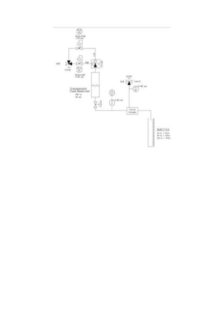


This document describes an experiment to determine the liquid permeability of a core sample using a liquid permeability device. The experiment involves applying confining pressure from a nitrogen gas supply, using another nitrogen gas supply to push water through the core sample, and measuring the flow rate and time taken to fill a graduated flask to calculate permeability based on Darcy's law. Safety warnings and references are also provided.


